As you are no doubt aware, electric motors are used everywhere in industry. From a technological point of view, they are quite complex devices, which sometimes makes it difficult to operate them to their maximum specifications.
It is very important to remember that the causes of breakdowns of the electric motor and its starting system are not limited to one area of technology. Engine failure can result from both mechanical and electrical causes. Therefore, proper maintenance of electric motors requires comprehensive knowledge and can reduce the likelihood of costly downtime, as well as increase the battery life of the unit. When an electric motor fails, there are few options to choose from. But before it fails, there is a lot you can do to prevent a possible malfunction or reduce the severity of its consequences. It is known that the most common failures of an electric motor are breakdown of winding insulation and wear of bearings. However, these are just consequences of a large number of reasons. Next, we will show you how to proactively detect the most common causes of failures, what tools you will need to do this, and give recommendations on choosing a strategy for successfully operating your electric motors.
Reasons for failure of electric motors
All faults can be divided into two groups - failure as a result of improper transportation or storage and breakdowns that appeared during operation.
Improper transportation and storage
The main problem that appears during this period is increased humidity, and even more so when the electric machine gets caught in the rain. This leads to a breakdown of the insulation, and in more severe cases, to the appearance of rust inside the device and bearings.
Therefore, before installing such a device, it is necessary to carry out routine repairs and eliminate the detected problems:
- carry out an external inspection of the machine, insulation on the terminals and internal jumpers;
- check the insulation condition with a megger;
- check the presence of lubrication and the condition of the bearings;
- in commutator motors of direct and alternating current, as well as in asynchronous machines with a wound rotor, the condition of the commutator or slip rings and brushes is determined.
All these operations are carried out in a warehouse or workshop near the site of future installation. If it is impossible to eliminate the problems, the electric machine is sent to a specialized enterprise for medium repairs.
Reasons for failure during operation
During operation, the main reasons for failure of an electric machine are:
- Mechanical wear of bearings. This occurs throughout the entire service life, as well as due to increased vibration and irregular lubricant changes. To prevent such situations, it is necessary to carry out full maintenance of all components and mechanisms. Failure to correct the malfunction in a timely manner leads to increased engine vibration, overheating of the bearing shields, wear of the bearing seats and jamming of the rotor.
- Destruction of the housing, bolts and bearing seats. Occurs due to increased vibration of the gearbox and poor alignment of the electric motor. The electric drive must be removed or replaced immediately. The consequences are similar to bearing failure.
- Motor overload and operation of three-phase devices in two phases. Correctly configured thermal relays protect against this. If there is no protection, the device will overheat above the maximum permissible temperature, which will lead to failure of the electric machine.
Reference! New electric motors are equipped with a temperature sensor that turns off the mechanism when the device overheats. It can also be additionally installed in the engine of an older model.
Causes of malfunction of the compressor of an industrial refrigeration unit
The compressor of an industrial refrigeration unit is designed to suck refrigerant vapors from the evaporator and reduce its pressure to the required boiling point. At the same time, with the help of a compressor, the pressure of the refrigerant vapor is increased to the level at which the saturation temperature exceeds the temperature of the medium that is used to cool the condenser and condense the refrigerant vapor.
When servicing refrigeration machines, you need to pay special attention to the direction of cooling of electric motors of semi-hermetic and hermetic compressors. The alternating operating mode of the equipment is especially dangerous, because Due to too frequent starts, the electric motor cannot process the heat accumulated after each peak mode.
Common electric motor malfunctions and methods for eliminating them
All faults can be divided into groups according to the place of their occurrence.
Signs of faulty windings, wiring and control circuitry
If there are problems in the windings, the motor must be replaced, and the wiring and control circuit must be repaired on site:
- The rotor (armature) does not rotate, the engine does not hum. There is no voltage in the network.
- The same thing, the protection is triggered. Short circuit in the wires or in the motor. It is necessary to disconnect the machine from the network and check the wiring. If there is no K.Z. The device is sent for repair.
- The engine does not rotate, but hums. Instead of three phases there are two. Correct the control scheme.
- The electric machine stopped while working. The protection worked. Check the thermal relay and all interlocks.
- The engine does not accelerate to rated speed. The device is overloaded or there is a short circuit in the windings. Check the current with a clamp meter. In case of overload, the current is increased in all phases and the gearbox is repaired or the actuator is adjusted. When there is a turn fault, the current in one phase is much higher than the others, and the motor must be replaced.
- Also, in a machine with a wound rotor. The current is rated, the resistance in the rotor circuit, the brush mechanism or a break in the rotor are faulty. Repair or replace resistors and brushes. If there is a break in the rotor, repairs are required in a specialized organization.
- The device hums and smokes. Short circuit inside the windings. The machine needs to be replaced and overhauled.
- After pressing the “STOP” button, the device works. The control circuit is faulty. Disconnect the network using a circuit breaker (not a switch) and make repairs.
Important! When the switch is turned off under load, there is a danger of an electric arc and burnout of the device.
Signs of faulty bearings
If the bearings are faulty, the machine can work for some time, but will quickly fail:
- The engine does not rotate, but hums, all phases are present. The rotor or gearbox is jammed. It is necessary to check the voltage
and try to turn the shaft manually - a jammed motor does not rotate, and if the gearbox is faulty, there is a slight play. When the bearing is destroyed, the shaft rotates normally without tension, and when turned on, the rotor is attracted to the stator. Disassemble the device and replace the bearings. - The bearing gets hot and knocks. Failure or lubricant has dried out. Remove the bearing and, if necessary, replace it completely or replace the lubricant.
Mechanical problems
- The electric motor is overheating. The device is overloaded or there is no ventilation. Check the current and restore the airflow of the machine.
- Increased vibration. The gearbox, coupling or bearings are faulty. Alignment is lost. Disconnect the engine from the gearbox, if the vibration disappears, then the alignment and gearbox are checked, if it persists, then a medium repair of the electric machine is carried out.
- Destruction of machine feet, bearing seats, mounting bolts. Strong vibration. Eliminate vibration and, if necessary, make minor repairs.
Features of testing electric motors with additional elements
Electric motors are equipped with additional elements to optimize operation or protection.
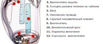
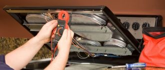
- Thermal fuses: disconnect the motor from the power supply when a temperature dangerous for the insulating materials is reached. They are located on the housing (attached with a bracket) or under the winding insulation. In the second case, the test is easier to perform because the conclusions are easily accessible. You can determine which detachable legs are connected to the protective circuit using a multimeter or a phase indicator (similar to a screwdriver with a light bulb). Normally, the resistance between the terminals of the thermal fuse is very small (short circuit).
- Thermal relays: often used instead of thermal fuses. Usually they are normally closed, but there are also open ones. To diagnose, using the markings on the relay body, in reference books or on the Internet, find the resistance of its components, then check their actual value with a multimeter. To search on the Internet, type the relay brand in the line followed by “Data Sheet”. If the thermal relay burns out, an analogue is selected based on its parameters.
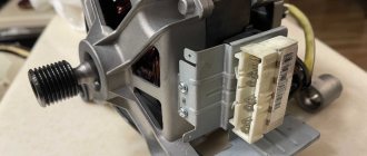
- Three-terminal engine speed sensors. Installed in washing machines. The main element of the sensor is a metal plate on which a potential difference is formed when small currents are passed through it.
The sensor is powered through the two outer terminals. If you touch them with the probes of a multimeter in ohmmeter mode, it will normally display a negligible resistance.
Checking the third pin is only possible in operating mode when a magnetic field is present. Trying to ring the sensor on the go, that is, with the washing machine turned on, can lead to injury. It is safer to simulate the operating mode by removing the engine and powering the sensor separately. Pulses at the sensor output are formed by rotating the rotor.
A multimeter allows you to identify, if not all, but many breakdowns of an electric motor. Mainly, using continuity testing, breaks and short circuits are detected. Full diagnostics are carried out on special stands; a megohmmeter is required to measure the insulation resistance.
Types of electrical machine repairs
To prevent malfunctions, maintenance and scheduled repairs of electrical equipment should be carried out according to the approved schedule.
Electrical machine repairs are divided into maintenance (MOT), current, medium and major repairs. The scope of work in each of these types of work is determined by the “Standard Regulations on Maintenance and Repair (MRO) of Electrical Equipment.”
Maintenance
This is to maintain equipment in working order between scheduled repairs. Carried out by maintenance and operational maintenance personnel.
Provides for the following types of work:
- inspection;
- heating check;
- wiping off dirt;
- insulation check;
- identifying faults and eliminating them.
It is carried out according to the approved schedule and during downtime - lunch break, adjustment, tool change.
Maintenance
Maintained in working condition until repaired. Produced on site or in a workshop. Includes:
- complex of maintenance works;
- replacement of failed components - bearings and couplings;
- adjustment and checking of alignment.
Medium renovation
For problems that cannot be eliminated during routine repairs, a medium repair is performed. This produces:
- complete disassembly;
- if necessary, replace bearings;
- repair of housing and shaft;
- impregnation of windings with varnish;
- insulation or replacement of leads
Medium repairs are carried out in specialized workshops and enterprises.
Various schemes for connecting asynchronous motors to a 380 volt network
In order to make the engine work, there are several different connection schemes, the most used among them are star and delta.
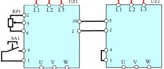
How to properly connect a three-phase star motor
This connection method is used mainly in three-phase networks with a linear voltage of 380 volts. The ends of all windings: C4, C5, C6 (U2, V2, W2) are connected at one point. To the beginnings of the windings: C1, C2, C3 (U1, V1, W1), - phase conductors A, B, C (L1, L2, L3) are connected through the switching equipment. In this case, the voltage between the beginnings of the windings will be 380 volts, and between the point of connection of the phase conductor and the point of connection of the windings will be 220 volts.
The electric motor plate indicates the possibility of connection using the “star” method in the form of a Y symbol, and it may also indicate whether it can be connected using another scheme. A connection according to this scheme can be with a neutral, which is connected to the connection point of all windings.
This approach allows you to effectively protect the electric motor from overloads using a four-pole circuit breaker.
A star connection does not allow an electric motor adapted for 380 volt networks to develop full power due to the fact that each individual winding will have a voltage of 220 volts. However, such a connection prevents overcurrent and the motor starts smoothly.
The terminal box will immediately show when the motor is connected in a star configuration. If there is a jumper between the three terminals of the windings, then this clearly indicates that this particular circuit is used. In any other cases, a different scheme applies.
We make the connection according to the “triangle” scheme
In order for a three-phase motor to develop its maximum rated power, a connection called “triangle” is used. In this case, the end of each winding is connected to the beginning of the next one, which in reality forms a triangle in the circuit diagram.
The winding terminals are connected as follows: C4 is connected to C2, C5 to C3, and C6 to C1. With the new marking it looks like this: U2 connects to V1, V2 to W1, and W2 to U1.
In three-phase networks, there will be a linear voltage of 380 volts between the terminals of the windings, and a connection to the neutral (working zero) is not required. This scheme also has the peculiarity that large inrush currents arise, which the wiring may not withstand.
In practice, a combined connection is sometimes used, when a star connection is used at the start-up and acceleration stage, and in operating mode special contactors switch the windings to a delta circuit.
In the terminal box, a delta connection is determined by the presence of three jumpers between the winding terminals. On the motor nameplate, the possibility of delta connection is indicated by the symbol Δ, and the power developed in star and delta configurations can also be indicated.
Three-phase asynchronous motors occupy a significant part among electricity consumers due to their obvious advantages.
The air outlet contains a large amount of moisture
The air supplied from the compressor may be very humid in the following cases:
- moisture has accumulated in the receiver;
- the air intake filter is very dirty;
- The compressor is located in a room with high humidity.
The following methods are applicable to combat moisture:
- Excess liquid from the receiver cylinder should be drained regularly;
- the filter element is washed or replaced;
- the unit is moved to another room where the air is drier or special filters are installed.
The air pressure in the receiver drops when the power is turned off
A drop in pressure indicates an air leak from the system. It happens:
- in the blowing path;
- in the receiver outlet valve;
- in the piston head control valve;
You need to carefully check the entire pipeline using a soap solution, covering the entire line. If a leak is found, it should be sealed.
The outlet valve may leak air if it is not tightly closed or due to a malfunction. If the tap is closed and the soap solution bubbles, the part must be replaced.
The problem may be with the piston head valve. In order to carry out further repairs of the air compressor, it is necessary to disassemble the cylinder head and remove any dirt that may have collected in the valve. Before starting work, be sure to bleed all compressed air from the receiver. If the pressure drops again, the valve needs to be replaced.
Air compressor device
To understand compressor problems, you need to clearly understand what elements it consists of and what they are intended for. A compressor, in its minimum configuration, consists of a supercharger (an engine that creates air flow) and a receiver - a container that contains compressed air. Piston compressors are most often used.
One of the main requirements for a compressor is its safety. If the pressure in the receiver is not controlled, the compressor will burn out. There is a high probability that the receiver cylinder may explode. To prevent this, the receiver is equipped with an electronic relay that automatically turns off the compressor when the air pressure reaches a certain value.
The air compressor is equipped with a pressure gauge that shows the amount of air pressure in the cylinder. To protect the compressor from negative influences, a check valve is used. Its main function is to prevent air from returning back to the compressor when turning off or otherwise interfering with the operation of the unit.
More complex compressor designs are characterized by the presence of additional equipment, such as automation for the compressor. Typically in small compressors, the automation unit maintains pressure up to eight atmospheres using a pressure switch, turning on or off the power to the electric motor when the minimum or maximum pressure in the receiver is reached.
In this case, there are two pressure gauges: the large one shows the pressure in the receiver cylinder, the small one at the outlet. The pressure switch can be equipped with a relief valve. When the unit stops, it will be open, which makes it easier to start the engine later.
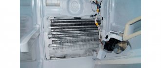
Some models have a cooling radiator on the air supply pipes from the compressor to the receiver.
Air cooling contributes to less condensation formation in the receiver. This little detail in the design extends the service life of the automation.
The presence of a drain valve allows you to quickly drain the condensate from the receiver, because it is advisable to end each session of operation of the unit with this operation.
The safety valve releases the increased pressure in the receiver if for some reason the automation does not work, which protects the compressor motor from overload.
The air filter protects the piston system from sand, dirt, and paint fumes.
The following types of compressors are distinguished:
- Volumetric action - holds gas or air in a confined space, increasing pressure. Among them are:
- rotary, the principle of operation is suction and compression of gas when the plates rotate; the working volume decreases, this leads to an increase in pressure.
- piston - pressure is created by the movement of pistons and valves; reliable in operation, but noisier than rotary ones.
- Dynamic - provide compression by increasing the speed of gas movement, increasing its kinetic energy, which is converted into compression energy. There are:
- centrifugal - used for air exchange in mines;
- axial or axial.
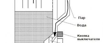
Let's consider how a piston-type compressor works; the air or gas in it is compressed by a piston that moves along the cylinder:
- As the piston (3) moves up the compressor cylinder (4), the working gas is compressed. The electric motor moves the piston through the crankshaft (6) and connecting rod (5).
- The suction and exhaust valves are opened and closed by gas pressure.
- The left diagram shows the gas suction phase into the compressor. When the piston moves downward, a vacuum is created in the compressor and the inlet valve (12) opens. Thus, gas enters the compressor space.
- The right diagram shows the gas compression phase. The piston rises and the outlet valve (1) opens. Gas leaves the compressor under high pressure.
operation scheme
The blower itself produces an uneven stream of air, which cannot be used, for example, for using a spray gun. The receiver saves the situation by smoothing out pressure pulsations.
What to do if engine overheating is detected
If the engine heats up during operation, it is necessary to diagnose it. To do this, you can use the step-by-step algorithm below.
- We assess the temperature. If the temperature is critical, you must immediately turn off the power to the engine.
- We evaluate the presence of extraneous sounds during operation (cracking, rattling, grinding). If the source of sound is in the drive mechanics (in the load), it is necessary to stop the engine and repair the faulty unit. If the sound is coming from the engine, the bearings will most likely need to be replaced.
- We check the current in phases using current clamps. If the current is exceeded, we can talk about an overload; if there is an imbalance in the phases, we can talk about phase imbalance, phase loss or phase-to-phase short circuit.
- If the bearings require regular lubrication, check and, if necessary, replace the lubricant.
- We disconnect the load from the motor shaft and check the operation of the engine in idle mode.
- Checking the operation of air cooling. If necessary, we clean the impeller and engine surface.
- We check the motor protection for compliance with the rated current indicated on the nameplate.