Dear site visitors!!!
I believe that the information presented in this topic will be useful to you. The topic will address various issues in this area, and many questions arise in this area:
- How does a household fan electric motor work?
- how to replace a capacitor in a fan's electrical circuit;
how to rewind the fan motor stator, how to repair:
- wall fan;
- ceiling fan;
- window fan;
- floor fan;
- bathroom fan;
- kitchen fan;
- fan with timer;
- exhaust fan.
It is almost impossible to immediately and completely provide information on issues that arise related to malfunctions resulting from the operation of various types of electric fans.
The topic will gradually expand, that is, after a certain period of time, additions will be made.
Take an interest in various sources of information in this direction:
- technical sites;
- technical literature
and so on. Accumulate your experience and knowledge.
Connection diagram for motor via capacitor
There are 2 types of single-phase asynchronous motors - bifilar (with a starting winding) and capacitor. Their difference is that in bifilar single-phase motors the starting winding operates only until the motor accelerates. Afterwards it is turned off by a special device - a centrifugal switch or a start-up relay (in refrigerators). This is necessary because after overclocking it reduces efficiency.
In capacitor single-phase motors, the capacitor winding runs all the time. Two windings - the main and auxiliary, they are shifted relative to each other by 90°. Thanks to this, you can change the direction of rotation. The capacitor on such engines is usually attached to the housing and is easy to identify by this feature.
Connection diagram for a single-phase motor via a capacitor
When connecting a single-phase capacitor motor, there are several options for connection diagrams. Without capacitors, the electric motor hums, but does not start.
- 1 circuit - with a capacitor in the power supply circuit of the starting winding - starts well, but during operation the power it produces is far from rated, but much lower.
- 3, the connection circuit with a capacitor in the connection circuit of the working winding gives the opposite effect: not very good performance at start-up, but good performance. Accordingly, the first circuit is used in devices with heavy starting, and with a working capacitor - if good performance characteristics are needed.
- Diagram 2 - connecting a single-phase motor - install both capacitors. It turns out something between the options described above. This scheme is used most often. She's in the second picture. When organizing this circuit, you also need a PNVS type button, which will connect the capacitor only during the start time, until the motor “accelerates”. Then two windings will remain connected, with the auxiliary winding through a capacitor.
Posts 1 page 7 of 7
Share1Tue, 5 Apr 2011 15:39
- Author: airobis
- contact
- Registered: Tue, 5 Apr 2011
- Posts: 4
- Respect: [+0/-0]
- Positive: [+1/-0]
- Spent on the forum: 46 minutes
- Last seen: Mon, 11 Apr 2011 14:40
Please provide a wiring diagram for a single-phase fan. It must be connected so that it turns on from either of the two light switches. One light switch for the first floor bathroom. second light switch for the second floor. Conditions: it is not possible to install additional switching, switching or switching elements. I put together a simple circuit that will turn on the fan from any of the two switches, AND THE LIGHTS WILL ALSO TURN ON IMMEDIATELY IN BOTH WAN UNITS (THIS DOESN’T MATTER MUCH). I'm more interested in whether there will be any security issues or similar things.
Share2Tue, 5 Apr 2011 15:49
- Author: kopernic
- power
- From: Voronezh
- Registered: Wed, 6 May 2009
- Posts: 56
- Respect: [+3/-1]
- Positive: [+0/-1]
- Age: 57 [1962-12-18]
- Time spent on the forum: 2 days 6 hours
- Last seen: Sat, 10 Sep 2011 21:20
I'm more interested in whether there will be any security issues or similar things.
They will if you have a three-phase input. Yes, and the lights will light up in two bathrooms at the same time.
Share3Tue, 5 Apr 2011 22:34
- Author: airobis
- contact
- Registered: Tue, 5 Apr 2011
- Posts: 4
- Respect: [+0/-0]
- Positive: [+1/-0]
- Spent on the forum: 46 minutes
- Last seen: Mon, 11 Apr 2011 14:40
. at which the fan will be turned on from any of the two switches, THE LIGHTS WILL ALSO BE TURNED ON IMMEDIATELY IN BOTH WAN UNITS (THIS DOES NOT MATTER MUCH). Besides this, are there any security issues?
Share4Wed, 6 Apr 2011 11:54
- Author: drug
- energy drink
- From: Astana
- Registered: Wed, 15 Aug 2007
- Posts: 2478
- Respect: [+216/-13]
- Positive: [+38/-9]
- ICQ: 393422521
- Spent on the forum: 1 month 13 days
- Last seen: Fri, 4 Apr 2014 09:50
airobis implements the idea:
. at which the fan will be turned on from any of the two switches, THE LIGHTS WILL ALSO BE TURNED ON IMMEDIATELY IN BOTH WAN UNITS (THIS DOES NOT MATTER MUCH). Besides this, are there any security issues?
The lights will also be turned off without mutual agreement between floors (a person will enter a lit bathroom without turning on their switch, and then at an interesting moment the upper switch will be turned off.). I propose a scheme in which there is actually a slight violation of safety regulations - there is a phase on the lamps and the fan, which is not encouraged by safety regulations (although in practice such inclusion is quite common). Simply replacing light bulbs and servicing lamps will have to be carried out with the machine turned off.
Edited by drug (Wed, 6 Apr 2011 11:57)
Connection diagram for a three-phase motor via a capacitor
Here, the voltage of 220 volts is distributed into 2 series-connected windings, where each is designed for this voltage. Therefore, the power is lost almost twice, but such an engine can be used in many low-power devices.
The maximum power of a 380 V motor in a 220 V network can be achieved using a delta connection. In addition to minimal power losses, the engine speed also remains unchanged. Here, each winding is used for its own operating voltage, hence the power.
It is important to remember: three-phase electric motors have higher efficiency than single-phase 220 V motors . Therefore, if there is a 380 V input, be sure to connect to it - this will ensure more stable and economical operation of the devices. To start the motor, you will not need various starters and windings, because a rotating magnetic field appears in the stator immediately after connecting to a 380 V network.
Reverse.
Sometimes it becomes necessary to change the direction of rotation of the electric motor. This option is also available for 380V motors used in a single-phase network. To do this, you need to make sure that the end of the capacitor connected to a separate winding remains unbroken, and the other can be transferred from one winding, where the “zero” is connected, to the other, where the “phase” is connected.
This operation can be performed by a two-position switch, the central contact of which is connected to the output from the capacitor, and to the two outer terminals from “phase” and “zero”.
More details can be seen in the figure.
Almost every day we are faced with the same question from our customers: “how to connect an electric motor to the power supply?”
The easiest and most reliable way is to contact a proper electrician and do not skimp on this, because... Often, in an attempt to save money, they invite “Uncle Vasya” or other sympathetic “specialists” who are nearby, but in fact have little understanding of what is happening. At best, these “pros” call and ask if I’m connecting correctly. There is still a chance not to burn the engine. The qualifications of an “electrician” immediately become clear when they ask such questions that you can simply fall into a stupor (since this is exactly what electricians are taught).
For example: - why are there six contacts in the engine? — why are there only three contacts? - What are “star” and “triangle”? — why, when I connect a three-phase pump and install a float switch that breaks one phase, the engine does not stop? — how to measure the current in the windings? — what is a starter? and so on.
If your electrician asks such questions, then you need to send him back to where he came from. Otherwise, everything will end with a burnt out electric motor, loss of money, time, and expensive repairs. Let's try to understand the diagrams for connecting an electric motor to the power supply. First you need to understand that there are several popular types of AC networks:
1. Single-phase network 220V, 2. Three-phase network 220V (usually used on ships), 3. Three-phase network 220V/380V, 4. Three-phase network 380V/660V. There are also voltages of 6000V and some other rare ones, but we will not consider them.
In a three-phase network there are usually 4 wires (3 phases and zero). There may also be a separate ground wire. But there are also ones without a neutral wire.
How to determine the voltage in your network? Very simple. To do this, you need to measure the voltage between phases and between zero and phase.
In 220/380 V networks, the voltage between phases (U1, U2 and U3) will be equal to 380 V, and the voltage between zero and phase (U4, U5 and U6) will be equal to 220 V. In 380/660 V networks, the voltage between any phases (U1 , U2 and U3) will be equal to 660V, and the voltage between zero and phase (U4, U5 and U6) will be equal to 380V.
Online calculation of motor capacitor capacity
Enter data for calculating capacitors - motor power and efficiency
There is a special formula that can be used to calculate the required capacity accurately, but you can easily get by with an online calculator or recommendations that are derived from many experiments:
The working capacitor is taken at the rate of 0.8 μF per 1 kW of engine power; The launcher is selected 2-3 times more.
Capacitors must be non-polar, that is, not electrolytic. The operating voltage of these capacitors must be at least 1.5 times higher than the network voltage, that is, for a 220 V network we take capacitors with an operating voltage of 350 V and higher. To make starting easier, look for a special capacitor in the starting circuit. They have the words Start or Starting in their markings.
Starting capacitors for motors
These capacitors can be selected using the method from smallest to largest. Having thus selected the average capacity, you can gradually add and monitor the operating mode of the engine so that it does not overheat and has enough power on the shaft. Also, the starting capacitor is selected by adding until it starts smoothly without delays.
During normal operation of three-phase asynchronous electric motors with capacitor start, connected to a single-phase network, it is assumed that the capacitance of the capacitor will change (decrease) with increasing shaft speed. At the moment of starting asynchronous motors (especially with a load on the shaft) in a 220 V network, an increased capacity of the phase-shifting capacitor is required.
Reverse.
Sometimes it becomes necessary to change the direction of rotation of the electric motor. This option is also available for 380V motors used in a single-phase network. To do this, you need to make sure that the end of the capacitor connected to a separate winding remains unbroken, and the other can be transferred from one winding, where the “zero” is connected, to the other, where the “phase” is connected.
This operation can be performed by a two-position switch, the central contact of which is connected to the output from the capacitor, and to the two outer terminals from “phase” and “zero”.
More details can be seen in the figure.
It happens that a three-phase electric motor falls into your hands. It is from such engines that homemade circular saws, emery machines and various types of shredders are made. In general, a good owner knows what can be done with it. But the trouble is, a three-phase network in private homes is very rare, and it is not always possible to install it. But there are several ways to connect such a motor to a 220V network.
It should be understood that the engine power with such a connection, no matter how hard you try, will drop noticeably. Thus, a delta connection uses only 70% of the engine power, and a star connection uses even less - only 50%.
In this regard, it is desirable to have a more powerful engine.
So, in any connection scheme, capacitors are used. In essence, they act as the third phase. Thanks to it, the phase to which one terminal of the capacitor is connected shifts exactly as much as necessary to simulate the third phase. Moreover, to operate the engine, one capacity is used (working), and for starting, another (starting) is used in parallel with the working one. Although this is not always necessary.
For example, for a lawn mower with a blade in the form of a sharpened blade, a 1 kW unit and only working capacitors will be sufficient, without the need for containers for starting. This is due to the fact that the engine is idling when starting and it has enough energy to spin the shaft.
If you take a circular saw, a hood or another device that puts an initial load on the shaft, then you cannot do without additional banks of capacitors for starting. Someone may say: “why not connect the maximum capacity so that there is not enough?” But it's not that simple. With such a connection, the motor will overheat and may fail. Don't risk your equipment.
Connection diagram and calculation of the starting capacitor
Failure of capacitors in the air conditioning compressor circuit is not so rare. Why do you need a capacitor at all and why is it there?
Low-power household air conditioners are mainly powered by a single-phase 220 V network. The most common motors used in air conditioners of this power are asynchronous with an auxiliary winding, they are called two-phase electric motors or capacitor motors .
In such motors, two windings are wound so that their magnetic poles are located at an angle of 90 degrees. These windings differ from each other in the number of turns and rated currents, and, accordingly, in internal resistance. But at the same time they are designed so that during operation they have the same power.
In the circuit of one of these windings, its manufacturers designate it as a starting winding, they include a working capacitor, which is constantly in the circuit. This capacitor is also called a phase-shifting capacitor, since it shifts the phase and creates a circular rotating magnetic field. The working or main winding is connected directly to the network.
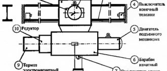
Description of the machine
Single-phase electric motors are usually called asynchronous single-phase electrical machines with low power. The magnetic core of such machines has a two-phase winding, which is divided into a starting (starting) and a main winding. The need for 2 windings is as follows: they must cause the rotor of the electric propulsion (single-phase) to rotate. At the moment, such devices are conventionally divided into 2 categories:
- Presence of starting windings. In this embodiment, the starting winding is connected through a starting capacitor. When the start is complete and the machine has reached its rated rotation speed, the starting winding is disconnected from the power supply. After which the engine continues to rotate on the working winding connected to the network (the capacitor charges during startup and turns off the starting winding). The required capacitor volume is usually indicated by the machine manufacturer on a plate with all the parameters (as a standard it should be on all engines).
- Machines with working capacitors. In such electrical machines, the auxiliary windings are always connected through capacitors. In this case, the volume of capacitors is determined by the design of the engine. In this case, the capacitor remains switched on even when the machine reaches the nominal operating mode.
To correctly connect an electrical machine, you must be able to determine (or know) how the starting and operating windings are wired, as well as their characteristics.
It is worth noting: these windings differ in the conductors used (their cross-section), as well as in the turns. So, for the working windings, conductors of a larger cross-section are used, and they have a larger number of turns. It is important to know that the resistance of the working windings of different machines is always less than the resistance of the starting/auxiliary windings. In this case, measuring the resistance of the motor winding is not difficult, especially if special multimeters are used.
Based on what has been described, it is worth giving some examples.
Calculation of the capacitance and voltage of the working capacitor
The calculation comes down to selecting such a capacitance so that at a rated load a circular magnetic field is provided, since at a value below or above the rated value the magnetic field changes its shape to an elliptical one, and this worsens the performance characteristics of the engine and reduces the starting torque. Engineering reference books provide a formula for calculating the capacitance of a capacitor:
Average = Isinφ/2 πf U n 2
I and sinφ – current and phase shift between voltage and current in a circuit with a rotating magnetic field without a capacitor
f- AC frequency
U – supply voltage
n - winding transformation coefficient, defined as the ratio of winding turns with and without a capacitor.
The voltage across the capacitor is calculated using the formula
Uc= U√(1+n 2 )
Uc - operating voltage of the capacitor
U - motor supply voltage
n - winding transformation ratio
The formula shows that the operating voltage of the phase-shifting capacitor is higher than the motor supply voltage.
Calculation manuals give an approximate calculation - 70-80 µF of capacitor capacity per 1 kW of electric motor power, and the capacitor voltage rating for a 220 V network is usually set at 450 V.
Also, a starting capacitor is connected in parallel to the working capacitor for the start-up period, for about three seconds, after which the relay is activated and turns off the starting capacitor. Currently, circuits with an additional starting capacitor are not used in air conditioners.
More powerful air conditioners use compressors with three-phase asynchronous motors; starting and running capacitors are not required for such motors.
Calculation of motor capacitor capacity
The winding with a smaller cross-section is the starting one. Such devices have a power factor greater than that of the short-circuited devices described above and develop greater torque in comparison with them. You can do this yourself or use online calculators. The circuit with a working capacitor does not provide for disconnecting the additional winding after starting and accelerating the engine.
If to connect an asynchronous motor you use not a three-phase network, but a household single-phase one, that is, power it through one winding, it will not work. Connecting capacitors (part 1)
Connecting a single-phase electric motor: using a magnetic starter
But there is another way - connecting a single-phase electric motor as a generator to produce three-phase voltage.
The magnetic field of the main winding maintains rotation for a long time. The solution is to install a 3-pole switch. This procedure is implemented by simply changing the order in which the starting winding is turned on when it is connected to the working winding. This is due to the fact that when only the working winding C1-C2 is connected to the network, a single-phase capacitor motor will have a pulsating magnetic field rather than a rotating one, that is, it will not start. It is necessary to connect chokes to each of the network wires to eliminate interference.
The magnetic circuit of single-phase motors contains a two-phase winding, consisting of a main winding and a starting winding. Control of starting current indicators in such motors is carried out by a frequency converter. This will be one of the network wires. The most convenient is a magnetic starter controlled from alternating current. All containers included in the circuit must be of the same type.
If after this the engine turns out to be hot, then: The bearings may be dirty, jammed, or simply worn out. The idea of using a starting capacitor is to include it in the circuit only at the moment the motor starts. Machines for processing raw materials, etc. Connecting a capacitor. How to connect a capacitor to an electric motor. Scheme.
Post navigation
There are other schemes for connecting a motor through a capacitor, but we will consider these issues another time in another article.
Operating principle and startup scheme
Capacitors that are in a circuit can be charged. The required torque is provided by the displacement of phase currents in the windings of the IM. And in many cases, electrical equipment is driven by three-phase motors.
If you look at a plate where two currents are indicated through a fraction, it will be the smaller of them. The working capacitor is connected permanently in the winding circuit, the starting capacitor is closed briefly through the start switch. Installation and selection of components Capacitors have considerable dimensions, so they do not always fit into the inside of the boron junction box on the electric motor housing. It doesn’t make sense to immediately start calculating the connection diagram.
The capacity of the starting capacitor should be 2.5 - 3 times greater than the working capacitor. If the engine starts easily and has enough power to operate, then everything has been selected correctly. Everything is connected simply, it is fed into the thick wires. connecting a 380 to 220 volt motor
Connecting a single-phase motor via a capacitor - 3 circuits
What happens with this?
If the heating is quite noticeable, then you need to look for its causes. If the capacity is significantly exceeded, intense heating will begin.
It is necessary that the rated voltage of the capacitor is equal to or greater than the calculated one. This is the optimal solution for achieving average performance. Afterwards it is turned off by a special device - a centrifugal switch or a start-up relay in refrigerators.
Secondly, and most importantly, the author was convinced in practice that even an extremely accurate calculation is not a guarantee of the correct operation of the engine. One of the windings is connected directly to the network, and the second is connected using a capacitor. In the geometric dimension, the windings in the stator are placed opposite each other. So, step by step, we figured out how to connect a three-phase asynchronous electric motor to a single-phase network and what you need to calculate and know for this.
Asynchronous or collector: how to distinguish
Two of them are stator structural elements connected in parallel. Based on the maximum current flowing through it, a magnetic starter belongs to one of seven standardized groups. In fact, the launcher only works for seconds. As a rule, the resistance of the windings will be no more than several tens of ohms.
For example, on the operating conditions of the engine itself, on the connection diagram, on the capacitors, or, more precisely, on their capacity. For this purpose, the circuit provides for the presence of a special button designed to open the contacts after the rotor reaches a given speed level. Another example when measurements can show 10 ohms, 10 ohms, 20 ohms.
When you need to quickly spin up the engine, a circuit with a starting capacitor is used. It makes no difference what kind of working winding you have and what kind of starting winding. For single-phase asynchronous AC motors with a running capacitor, the auxiliary winding is permanently connected through a capacitor. But in any case, losses will range from 30 to 50 percent.
The most common motors of this type can be divided into two groups: single-phase motors with a starting winding and motors with a running capacitor. She's in the second picture. Connect a three-phase motor to a single-phase network. Starting and running capacitors.
Subscribe to the newsletter
An exhaust fan is a device that can increasingly be seen in the homes of our fellow citizens. There are several reasons for this. Firstly, recently, thanks to a significant reduction in the cost of production of such devices, almost everyone can afford such a purchase. Secondly, this electrical appliance is certainly a very useful acquisition for an apartment or a private house.
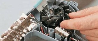
Electrical circuit of a household fan and its features
The main task of an exhaust fan is to provide forced artificial air circulation in rooms where natural circulation is difficult or insufficient. A striking example of such a room is the bathroom. In apartment buildings, as a rule, this room is located far from the external load-bearing walls, and, therefore, air circulation in them is difficult. If we add to this increased humidity and the mold that arises from it, then it immediately becomes clear that an exhaust fan in the bathroom is not just a tribute to fashion, but a real necessity.
In order to connect the fan, you need to know a few small nuances. You need to understand that the electrical connection diagram of the fan is largely determined by the location of its installation and the presence of design features.
Basic connection diagrams:
1. Connection with built-in switch. The simplest scheme. The device is supplied with 220 V power. The fan is turned on and off using a switch built into the device.
2. Connection via a switch. Using this scheme, the fan is turned on and off using a special switch. As a rule, it is located in front of the entrance to the room. For such a connection, it is necessary to lay 2 cables - one from the junction box to the switch, the second to the device itself.
3. Connecting a fan with a timer. The peculiarity of these devices is that they do not turn off immediately, but after a certain time. This is done through a special time relay, which automatically turns off the device after a predetermined period of time (usually from one minute to half an hour). With this connection, one wire goes to the switch, and two to the device.
4. Connecting a fan with a humidity sensor. The electrical fan control circuit may include a humidity sensor that measures readings in real time and, in accordance with a given program, monitors the operation of the device - it turns it on when humidity rises and turns it off when it reaches optimal values. The device connection diagram is similar to that needed to connect a fan with a timer.
Most fans consist of switching circuits, starting circuits, and electric motor windings. The items on the list concern repairs. Often in household models, a trivial coil is used, wound with a copper core with varnish insulation. Today we will consider how to repair fans with your own hands, the inductance burned out, the wire broke due to the carelessness of the operator. To restore the coil, a good old device is used, despite its simplicity, you cannot get it in the store. With the help of a mechanism, inductors are wound using an electric drive, working with handles.
Industrial fans are different; unlike household fans, they are often centrifugal. The winding of a commutator asynchronous motor cannot be restored at home; it will be difficult to do. Craftsmen repeat the factory production cycle in their native lands.
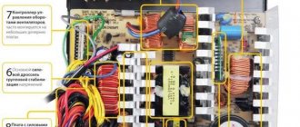
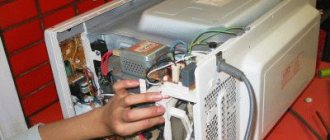
CONNECTING A COMPUTER FAN TO A 220 V NETWORK
In the process of resuscitation and modernization of Solntsev’s amplifier, we had to get rid of the bulky power supply made on the TS-180 transformer. A switching power supply based on IR2153 with a power of 200 W was manufactured. However, during operation, with a removed power of about 130 W, heating of the pulse transformer was detected. Not critical, but still present. In addition, the stabilizers L7815 and L7915 heated up quite noticeably. The tight mounting on the board did not allow installing large radiators.
To eliminate this effect I decided to use a cooler. The choice settled on a small-sized fan with a power of 0.96 W with a power supply of 12 volts and a current consumption of 0.08 A. Since a transformer power supply for it would have unacceptable weight and dimensions, I decided to assemble a transformerless power supply with a quenching capacitor.
How to connect a duct fan
Hello, dear visitors of the site D-Electric.ru . In the article “Connecting a fan,” I already talked about ways to connect exhaust fans, but I missed such an important issue as connecting two-speed duct fans . This, in fact, is what we will talk about today.
Duct fan installation
Installation example of a duct fan
As you can see, the installation of a duct fan differs significantly from the installation of a conventional wall fan - this is already a whole system, which, moreover, is installed behind a suspended ceiling. More expensive, but, as experts say, more effective. In general, I have nothing to say about the “subtleties” of installing such systems - here it is better to turn to professionals. So let's move straight to the connection.
Connecting duct fans
Duct fans can be single-speed or two-speed. As for the first ones, their connection diagram is not at all different from the connection diagram for wall-mounted exhaust fans. But with two-speed ones it’s a little more complicated. For them it is necessary to install a separate switch, or rather a speed switch.
Speed switch connection diagram
The idea is as follows: ground (PE), zero and two phase wires La and Lb are connected to the corresponding terminals of the two-speed fan. In this case, the zero and ground are not “broken” anywhere and have constant contact with the fan terminals, and the phase, depending on the required fan rotation speed, is supplied either to the La or Lb terminal. It is impossible to supply “power” to La and Lb at the same time - the fan will burn out.
Scheme
In general, a transformerless power supply is a symbiosis of a rectifier and a parametric stabilizer. Capacitor C1 for alternating current is a capacitive (reactive, i.e., not consuming energy) resistance Xc, the value of which is determined by the formula:
where f is the network frequency (50 Hz); C is the capacitance of capacitor C1, F. Then the output current of the source can be approximately determined as follows:
where Uc is the network voltage (220 V).
With a consumption current of 0.08 A, capacitance C1 should have a nominal value of 1.2 μF. Increasing it will allow you to connect a load with a large current consumption. Approximately, you can focus on 0.06 A for each microfarad of capacitance C1. I had 2.2 microfarads at 400 volts on hand.
Resistor R1 serves to discharge the capacitor after turning off the power supply. There are no special requirements for it. Nominal 330 kOhm - 1 Mohm. Power 0.5 – 2 W. In my case 620 kOhm 2 W.
Capacitor C2 serves to smooth out the ripples of the bridge-rectified voltage. Rating from 220 µF to 1000 µF with an operating voltage of at least 25 volts. I installed 470 uF at a voltage of 25 volts.
1N4007 from a used energy-saving lamp were used as rectifier diodes.
The zener diode (12 Volts) serves to stabilize the output voltage and by replacing it you can achieve almost any required voltage at the output of the power supply unit.
When assembling the circuit, you should keep in mind that the fan connection should be made correctly from the beginning. An error in soldering the fan wires in the wrong polarity will cause the fan to fail. And the connection itself (soldering) should be done in advance, since the no-load voltage at the fan connection points can be 50-100 volts. If the polarity is correct (the red wire is the positive power bus), then when connected to a 220 V network, the fan will have approximately +12 volts.
The printed circuit board is made using the LUT method. Etching was carried out with hydrogen peroxide, citric acid and table salt at the rate of 50 ml of peroxide, 2 tsp. acid and a teaspoon of salt.
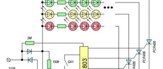
In addition, I provide a diagram (maybe someone will need it) for adjusting the fan speed.
Essentially, this is a voltage regulator supplied to the fan motor. A change in voltage leads to a change in fan speed. A constant resistor R2 was specially introduced into the circuit, the purpose of which is to limit the minimum fan speed, so that even at the lowest speed, i.e. at the lowest voltage, ensure its reliable start.
Product characteristics
To correctly install a duct fan with your own hands, each user needs to know its technical characteristics:
- max air flow - 5330 m³/h;
- max pressure - 900 Pa;
- perforations for fastening to pipelines - 100-400 mm;
- low level of sound exposure;
- performance can be adjusted;
- installation is quick and does not require any special skills;
- Maintenance and timely cleaning during operation do not take much time.