General definitions
The physical process in which charged particles move in an orderly (directional) manner is called electric current. It is usually divided into variable and constant. For the first, the direction and magnitude remain unchanged, but for the second, these characteristics change according to a certain pattern.
The above definitions are greatly simplified, although they explain the difference between direct and alternating current. To better understand what this difference is, it is necessary to provide a graphical representation of each of them, as well as explain how the alternating electromotive force is generated in the source. To do this, let us turn to electrical engineering, or rather its theoretical foundations.
Voltage as pressure
Voltage is very similar to electron pressure and indicates how fast and with what force they move through a conductor. These physical quantities are equivalent in many respects, including their relation to the strength of the pipeline-cable. Just as too much pressure ruptures a pipe, too much voltage destroys or pierces a conductor's shielding.
EMF sources
Sources of electric current of any kind are of two types:
- primary, with their help, electricity is generated by converting mechanical, solar, thermal, chemical or other energy into electrical energy;
- secondary, they do not generate electricity, but convert it, for example, from variable to constant or vice versa.
The only primary source of alternating electric current is a generator; a simplified diagram of such a device is shown in the figure.
Simplified illustration of generator design
Designations:
- 1 – direction of rotation;
- 2 – magnet with poles S and N;
- 3 – magnetic field;
- 4 – wire frame;
- 5 – EMF;
- 6 – ring contacts;
- 7 – current collectors.
Visualization challenges
Most people have no problem understanding concepts like pressure, quantity, and flow because they encounter them all the time in their daily lives. For example, it is easy to understand that increasing the flow when watering flowers will increase the amount of water coming out of the watering hose, while increasing the water pressure will cause it to move faster and with more force.
Electrical terms such as "voltage" and "current" are usually difficult to understand because you cannot see or feel the electricity moving through cables and electrical circuits. It is extremely difficult for even a novice electrician to visualize what is happening at the molecular level or even clearly understand what, for example, an electron is. This particle is beyond human sensory capabilities and cannot be seen or touched unless a certain amount of it passes through the human body. Only then will the victim definitely feel them and experience what is commonly called an electric shock.
However, exposed cables and wires appear completely harmless to most people simply because they cannot see the electrons just waiting to take the path of least resistance, which is usually the ground.
Principle of operation
Mechanical energy is converted by the generator shown in the figure into electrical energy as follows:
Due to such a phenomenon as electromagnetic induction, when the frame “4” rotates, placed in the magnetic field “3” (arising between the different poles of the magnet “2”), an emf “5” is formed in it. Voltage is supplied to the network through current collectors “7” from ring contacts “6”, to which frame “4” is connected.
Video: direct and alternating current - differences
As for the magnitude of the EMF, it depends on the speed of intersection of the power lines “3” by the frame “4”. Due to the characteristics of the electromagnetic field, the minimum crossing speed, and therefore the lowest value of the electromotive force, will be at the moment when the frame is in a vertical position, respectively, the maximum - in a horizontal position.
Taking into account the above, in the process of uniform rotation an emf is induced, the characteristics of the magnitude and direction of which change with a certain period.
Story
Thomas Edison's company, which was called Edison Electric Light, was founded in the late 70s of the 19th century. Then, in the days of candles, kerosene lamps and gas lighting, incandescent lamps produced by Edison could work continuously for 12 hours. And although now this may seem ridiculously little, it was a real breakthrough. But already in the 1880s, the company was able not only to patent the production and transmission of direct current via a three-wire system (these were “zero”, “+110 V” and “-110 V”), but also to introduce an incandescent lamp with a resource of 1200 hours .
It was then that Thomas Edison’s phrase, which later became known throughout the world, was born: “We will make electric lighting so cheap that only the rich will burn candles.”
Well, by 1887, more than 100 power plants were successfully operating in the United States, which generate direct current and where a three-wire system is used for transmission, which is used to at least slightly reduce electricity losses.
But the scientist in the field of physics and mathematics, George Westinghouse, after reading Edison’s patent, found one very unpleasant detail - it was a huge loss of energy during transmission. At that time, there were already alternating current generators, which were not popular due to the equipment that would operate on such energy. At that time, the talented engineer Nikola Tesla was still working for Edison in the company, but one day, when he was once again denied a salary increase, Tesla could not stand it and went to work for a competitor, which was Westinghouse. In a new place, Nikola (in 1988) creates the first electricity meter.
It is from this moment that the “war of currents” begins.
Graphic images
Thanks to the use of the graphical method, it is possible to obtain a visual representation of dynamic changes in various quantities. Below is a graph of voltage changes over time for a 3336L (4.5 V) galvanic cell.
The horizontal axis displays time, the vertical axis shows voltage
As you can see, the graph is a straight line, that is, the source voltage remains unchanged.
Now we present a graph of the dynamics of voltage changes during one cycle (full revolution of the frame) of the generator.
The horizontal axis displays the angle of rotation in degrees, the vertical axis displays the magnitude of the emf (voltage)
For clarity, we will show the initial position of the frame in the generator, corresponding to the starting point of the report on the graph (0°)
Frame initial position
Designations:
- 1 – magnet poles S and N;
- 2 – frame;
- 3 – direction of rotation of the frame;
- 4 – magnetic field.
Now let's see how the EMF will change during one cycle of rotation of the frame. At the initial position, the EMF will be zero. During the rotation process, this value will begin to increase smoothly, reaching a maximum at the moment when the frame is at an angle of 90°. Further rotation of the frame will lead to a decrease in the EMF, reaching a minimum at the moment of rotation by 180°.
Continuing the process, you can see how the electromotive force changes direction. The nature of the changes in the EMF that has changed direction will be the same. That is, it will begin to increase smoothly, reaching a peak at the point corresponding to a 270° rotation, after which it will decrease until the frame completes a full rotation cycle (360°).
If the graph is continued for several rotation cycles, we will see a sinusoid characteristic of alternating electric current. Its period will correspond to one revolution of the frame, and its amplitude will correspond to the maximum value of the EMF (forward and reverse).
Now let's move on to another important characteristic of alternating electric current - frequency. The Latin letter “f” is used to denote it, and its unit of measurement is hertz (Hz). This parameter displays the number of complete cycles (periods) of EMF change within one second.
The frequency is determined by the formula: . The “T” parameter displays the time of one complete cycle (period), measured in seconds. Accordingly, knowing the frequency, it is easy to determine the time of the period. For example, in everyday life an electric current with a frequency of 50 Hz is used, therefore, its period time will be two hundredths of a second (1/50 = 0.02).
Application
Use in electronics to power circuits is not the end use case for DC. Direct current has found use in the following cases:
- in electrolysis – production of metals from salts and solutions on an industrial scale;
- galvanoplasty and galvanization - metal coating of electrically conductive surfaces;
- in welding work – work with stainless steel;
- in transport - engines of trams, electric locomotives, trolleybuses, icebreakers, submarines;
- in medicine – the introduction of drugs into the body through electrophoresis.
For information. In the USSR, the electrification of the railway with direct current began on the sections of Baku - Suramsky Pass and Sabuchini. Before the Great Patriotic War, the voltage was 1.5 kV, then it was transferred to 3 kV. In total, half of the railway lines operated from this type of current.
Three-phase generators
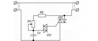
Note that the most cost-effective way to obtain alternating electric current is to use a three-phase generator. A simplified diagram of its design is shown in the figure.
Three-phase generator device
As you can see, the generator uses three coils, placed with an offset of 120°, connected to each other by a triangle (in practice, such a connection of the generator windings is not used due to low efficiency). When one of the poles of the magnet passes by the coil, an emf is induced in it.
Graphical representation of the generated three-phase electric current
Current as flow
Current is the flow rate of electrons, indicating how many electrons are moving through the cable. The higher it is, the more electrons pass through the conductor. Just as large amounts of water require thicker pipes, large currents require thicker cables.
Using the water circuit model allows you to explain many other terms. For example, power generators can be thought of as water pumps, and electrical loads can be thought of as water mills that require water flow and pressure to rotate. Even electronic diodes can be thought of as water valves that only allow water to flow in one direction.
What is the reason for the variety of electric currents?
Many may have a well-founded question - why use such a variety of electric currents if you can choose one and make it standard? The thing is that not every type of electric current is suitable for solving a particular problem.
As an example, we give conditions under which using constant voltage will not only be unprofitable, but sometimes impossible:
- the task of transmitting voltage over distances is easier to implement for alternating voltage;
- it is almost impossible to convert direct electric current for heterogeneous electrical circuits that have an uncertain level of consumption;
- maintaining the required voltage level in direct current circuits is much more difficult and expensive than alternating current;
- motors for alternating voltage are structurally simpler and cheaper than for direct voltage. At this point, it should be noted that such motors (asynchronous) have a high level of starting current, which does not allow them to be used for solving certain problems.
Now we give examples of problems where it is more appropriate to use constant voltage:
- To change the rotation speed of asynchronous motors, you need to change the frequency of the power supply network, which requires complex equipment. For motors running on direct current, it is enough to change the supply voltage. That is why they are installed in electric vehicles;
- power supply of electronic circuits, galvanic equipment and many other devices is also carried out by direct electric current;
- DC voltage is much safer for humans than alternating voltage.
Based on the examples listed above, there is a need to use different types of voltage.
Symbols on electrical devices and diagrams
Often there is a need to determine at what current a device operates. After all, connecting a device operating on direct current to an alternating current electrical network will inevitably lead to unpleasant consequences: damage to the device, fire, electric shock. For this purpose, there are generally accepted symbols in the world for such systems and even color marking of wires.
Conventionally, on electrical appliances operating on direct current, one line, two solid lines, or a solid line together with a dotted line, located one below the other, are indicated. Also, such a current is marked with the Latin letters DC . The electrical insulation of wires in DC systems is colored red for the positive wire and blue or black for the negative wire.
On electrical devices and machines, alternating current is denoted by the English abbreviation AC or a wavy line. On diagrams and in descriptions of devices, it is also designated by two lines: solid and wavy, located one below the other. Conductors in most cases are designated as follows: phase - brown or black, neutral - blue, and ground - yellow-green.
Efficiency of Electronic Commutated Motors
EC motors are brushless DC motors controlled by external electronics - either an electronic board or a frequency converter.
The rotor contains permanent magnets, and the stator has a set of stationary windings. Switching is performed using electronic circuits. The “board” switches phases in the stationary windings to keep the motor turning. This allows the armature current to be maintained. When the voltage of the correct polarity is connected at the right time, the accuracy of the electrical machine increases. Because the motor speed is controlled by external electronics, EC motors do not have a limited synchronous speed. EC motors have several advantages. Since they do not have brushes, they do not spark and their service life is longer due to the absence of brushes, they have less losses due to the “smart control” of the stator. They provide better performance and controllability than induction motors. In terms of size, small electric motors can reach the same dimensions as traditional AC or DC electric machines.
Power distribution is much better with electronically controlled cars. Brushless direct current (BLDC) motors rely on a constant voltage power supply. When using AC machines, there are additional costs and system complexity if regulation is required. EC motors can be directly connected to AC sources thanks to the presence of an electronic control system. Moreover, they are slightly susceptible to changes in the frequency and voltage of the network, from which we can conclude that small dips in the network voltage will not have a significant effect on the power of the machine, unlike asynchronous electric motors.
If you compare the efficiency of an EC machine with an alternating current machine with a shaded pole or with a capacitor electric motor, you can see that a shaded pole machine has an efficiency of about 15% - 25%, capacitor electric motors 30% - 50%, and EC machines have an efficiency within the range 60% - 75% and are the most efficient and energy saving.
The range of changes in efficiency for capacitor asynchronous machines is quite large and lies in the range of 30% - 50%, which is especially noticeable when they are not fully loaded, for example, when working in ventilation and air conditioning systems. EC motors have a smaller range of efficiency changes when operating at different speeds and with different loads. As a rule, such machines have an efficiency of at least 70%, and in machines operating with nominal parameters it can exceed 80%.
Electronically controlled machines have a speed controller as a built-in option. AC motors can only have this option with an external controller (frequency converter). Frequency converters change the amplitude and frequency of the voltage supplied to the electric motor, thereby generating higher harmonics, which negatively affect the electric machine, contributing to its overheating, and, as a result, reducing its service life.
The switching circuits accept pulse width modulated inputs from 4 to 20 mA and 0 to 10 V. This allows speed control from 10% to 100%. Monitoring EC motors using an integrated circuit is simple and can be easily accessed by the designer to provide feedback. Finally, EC motors provide smooth starting, reduced noise and lower motor temperatures.
Electronically controlled electrical machines are typically used for low power applications such as small fans, servo motors, and motion control systems. However, thanks to recent advances in electronics and chemistry, EC motors are finding their way into larger manufacturing applications, up to 12 kW and above.
Video
Coffee capsule Nescafe Dolce Gusto Cafe O Le Coffee with milk, 3 packs of 16 capsules each
1305 ₽ More details
Coffee capsules Nescafe Dolce Gusto Café Au Lait, 16 pcs.
435 ₽ More details
Apple iPhone XR 128GB
Conversion
For household appliances that require circuits to be supplied with DC type electricity, it is supplied through power supplies. These are circuits that include a step-down transformer and a rectifying unit. When connecting the power supply to the device, make sure that their voltage and power parameters match. The parameters are indicated on the device body.
Mains power supply 50 Hz
At the moment, both types of electricity get along well in the modern world. Mixed nutrition schemes of consumers only complement each other.
ru.natapa.org
Alternating current and direct current are two different forms of currents that are used to transmit electricity throughout the world. Both currents are the same because they use electron flows to transmit electricity, but that's where the similarities end. Alternating current is the most common type of electricity that is transmitted by power plants and is used to power buildings, offices, homes, etc.
Direct current (DC) was the predominant form of electricity used in the 19th century and was also used in the first commercial transmission of electricity by Thomas Edison. Direct current means that power flows in one direction. In direct current, the flow of electrons is in a constant direction, without changing at regular intervals, and is achieved by installing permanent magnets on the wire, which help the electrons stay on a steady path. Direct current was originally called "galvanic current". Direct currents flow in conductors such as wires, but can also pass through semiconductors, insulators, or even a vacuum. Direct currents can be generated using sources such as batteries, thermocouples and solar cells. The chemical energy inside the battery is powerful enough to push the electrons rather than pull them, causing the energy to flow in one direction.