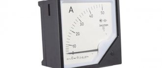
To measure the current in an electrical circuit, there are instruments called ammeters. They are connected to the circuit in a series circuit. The internal resistance of ammeters is very small, so such a measuring device does not affect the parameters of the electric current of the measured circuit. The unit of current is ampere.
There are two main types of ammeters:
The first type is in turn divided into the following devices:
According to the type of current measured, ammeters are divided:
There are other specialized current measuring instruments that are used in specific areas and are not as widely used as those listed above.
Design features and operation
Current and voltage measurement. Voltmeter and ammeter.
All types of devices use a corrector - a special screw connected to a spring. It is necessary to set the arrow to the zero position.
Expert opinion
It-Technology, Electrical power and electronics specialist
Ask questions to the “Specialist for modernization of energy generation systems”
Current strength. Ammeter - lesson. Physics, 8th grade. Due to the digital multimeter's resistance to external conditions, temperature and pressure changes, it can be used in environments with vibration and shaking. Ask, I'm in touch!
Ammeters. Types and work. Device and application. Peculiarities
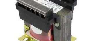
Instrument scales can be graduated in different fractions of an ampere: microamperes, milliamperes, etc. Accordingly, such devices are called microammeters, milliammeters, etc. To expand the measurement limits, ammeters are connected to a circuit using a transformer, or in parallel with a shunt. In this case, only a small part of the current will flow through the ammeter, and the main part of the current will flow through the shunt.
Special nuts are used to attach the shunt to the ammeter. It is forbidden to connect the shunt to the ammeter when the power supply is turned on. The polarity of the device when connecting is also of great importance. If you reverse the polarity, the arrow of the device will go in the other direction, and the digital ammeter will show a negative value.
Magnetoelectric ammeters
The operating principle of this type of device is based on the interaction of the magnetic field of a magnet and a moving coil located in the device body.
The advantages of such an ammeter are low power consumption during operation, high sensitivity and measurement accuracy. All magnetoelectric ammeters are equipped with a uniform graduation of the measurement scale. This allows measurements to be made with high accuracy.
The disadvantages of a magnetoelectric ammeter include its complexity of internal design and the presence of a moving coil. Such a device is not universal, since it only operates for direct current.
Despite the disadvantages, the magnetoelectric type of device is widely used in various fields of industry and in laboratory conditions.
Electromagnetic
Ammeters with an electromagnetic operating principle do not have a moving coil in their design, unlike magnetoelectric models. Their device is much simpler. The housing contains a special device and one or more cores that are mounted on an axis.
What kind of lighting do you prefer?
Built-in Chandelier
An electromagnetic ammeter has less sensitivity compared to a magnetoelectric device. This means that the accuracy of its measurements will be lower. The advantage of such devices is their versatility. This means that they can measure current in both DC and AC circuits. This significantly expands its scope of application.
Electrodynamic
The method of operation of such devices is the interaction of electric fields of currents that pass through electromagnetic coils. The design of the device consists of a moving and a fixed coil. Universal operation on any type of current is the main advantage of electrodynamic ammeters.
How to measure current in an electrical circuit with an ammeter yourself
For what purpose might it be necessary to measure current strength? What is the benefit to us from knowing the number of charged particles flowing through a unit cross section per unit time? There is a benefit, and the value of this information is great!
By using only an ammeter, you can quickly determine the correct installation and avoid the costs of replacing or repairing damaged electrical equipment. The ammeter reading will tell you whether there is a short circuit or other leaks or problems in the circuit. Knowing the current consumption will not be superfluous when choosing a particular fuse.
Current characteristics
Direct current is characterized by two main parameters - current and voltage. Current strength is simply the number of particles that move in a conductor in a certain direction. The more of these particles, the greater the work done by the electric current.
Current strength is measured in amperes (you need to know that a microamp is one millionth of an ampere, a milliamp is one thousandth of an ampere).
The current strength is measured with an ammeter. The ammeter must be connected in series with the current collector.
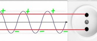
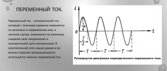
In addition to direct current, there is alternating current. Alternating current changes its direction and amplitude over time. Electricity generators produce alternating current. Alternating current changes over time according to a sinusoidal law. To characterize it, there are additional parameters - amplitude and frequency.
Types of devices
Devices are classified according to the type of current, operating principle, and accuracy class.
Type of current
Variable
An ammeter device connected in series to an electrical circuit passes the full operating current through itself. In this case, the resistance of the ammeter should be quite low. This factor is the basis of the operating principle of the electrical meter.
Important! The ammeter cannot be connected in parallel to a circuit, only in series. Because all the electric current will flow through it, as a result of which the device may burn out.
Ideally, the device should have zero resistance and voltage drop, then the power loss in the electrical device will be zero. But such ideal conditions are practically unattainable. In fact, the lower the impedance, the better the device compatibility.
Constant
In low-voltage battery circuits, currents are usually measured by highly sensitive mini-devices called galvanometers. A galvanometer is a device used to detect current in a circuit. In this case, the device itself works as an electric drive. It produces a rotating movement of the pointer in response to an electric current flowing through coils in a constant magnetic field.
Operating principle
Analog
Magnetoelectric
Such a device is not universal, since it is used only for measuring direct current. The scope of application of magnetoelectric devices widely extends to the areas of industry and education (as components of laboratory installations).
For your information. The main disadvantage is the high cost.
Electromagnetic
The circuit of electromagnetic meters is simple. The housing may contain several cores (or one) mounted on an axis. Unlike magnetoelectric models:
- With their help, both direct and alternating current are measured. This makes electrical devices universal and significantly expands the scope of their application;
- Low energy consumption during operation;
- High sensitivity and accuracy of measurements.
Electrodynamic
The electrodynamic ammeter is designed in a somewhat more complex manner than previous electrical devices. It has two coils: one is fixed, and the second is movable.
Instruments of this type can be used to measure both direct and alternating current. Another advantage is the absence of hysteresis error. The main disadvantages are low torque coefficient, high friction losses, higher than in other measuring instruments.
Expert opinion
It-Technology, Electrical power and electronics specialist
Ask questions to the “Specialist for modernization of energy generation systems”
Electrical measuring instruments: ammeter, voltmeter, ohmmeter. They are also used in the domestic sphere among car owners to carry out independent measurements of automotive devices. Ask, I'm in touch!
Real examples of current measurement
Next, we will consider several options for how to connect a measuring device for domestic needs. When measuring batteries, you need to attach one probe to the battery contact, and the second to the load contact, the second load contact is connected to the free terminal of the battery.
Rice. 4. Measuring the current in the battery circuit
If you want to check the current load in the windings of a three-phase electric motor, connect the measuring device to each phase in turn, or if you have three ammeters, you can use them simultaneously. To do this, the probes are connected at one end to the terminals of the windings in the boron, and at the other end to the supply wire of the corresponding phase.
Rice. 5. Measuring current in the electric motor circuit
How to use an ammeter
When dealing with electrical current, every precaution should be taken to avoid personal injury due to a short circuit. To do this you need:
Important! Before performing work, you should familiarize yourself with the power supply diagram to avoid mistakes. Connect the plus to the positive and minus to the negative connector of the device in the DC circuit. If the circuit is with alternating current, then the order of connection does not matter.
Many people think that to measure high currents they need to buy a new device or change the design of the old one. But nothing like this can be made from an existing device with the required range. To do this, use one of the following methods:
An example of finding an ammeter reading from the given error
For example, we consider an analog meter with a scale of up to 25 A.
The scale has a designation of accuracy class 2.5, there is no circle or square, so this error is given.
At Xp = 25A and p value = 2.5, the absolute error can be calculated:
If the user finds an accuracy class enclosed in a square on the panel, then the error will need to be determined as a percentage of the measured value.
With scale readings Ii = 10 A, the instrument error should not exceed
When reading on a scale Ii = 2 A, the error will be different:
When reading on a scale Ii = 25 A, the error will be maximum:
This is why it is important that an analog instrument operates at 2/3 of the operating scale.
Voltage measurement. Voltmeter.
If there were no voltmeter in the circuit, the current through the resistors would be the same and determined by Ohm’s Law as follows:
As with the ammeter, there is a special method that allows you to increase the voltage measurement limits of the voltmeter. To do this, it is necessary to connect an additional resistance in series with the device, the value of which is determined by the formula:
This will cause the voltmeter to be n times less than the measured voltage. As usual, let's look at a small practical example:
Here we added additional resistance R_3 to the circuit. Our task is to measure the voltage across the resistor R_2:\medspace U_2 = R_2\medspace I_2. Let's determine what result the voltmeter will give us when turned on in this way:
Let's substitute the expression for calculating the resistance of the additional resistor into this formula:
Thus: U_B = \frac . That is, the voltmeter readings will be n times less than the voltage value that we measured. So, using this method, it is possible to significantly increase the measurement limits of the voltmeter.
At the end of the article, a few words about measuring resistance and power.
In general, this is probably the end of today, stay tuned!
Expert opinion
It-Technology, Electrical power and electronics specialist
Ask questions to the “Specialist for modernization of energy generation systems”
How to connect an ammeter Current strength I is a scalar quantity equal to the ratio of the charge q passing through the cross section of the conductor to the time period t during which the current flowed. Ask, I'm in touch!
How to correctly record readings of measuring instruments, taking into account the error
When recording values (taking into account the error), you should use the formula:
where A is the measured quantity, a is the measurement result, Δa is the measurement error.
The measurement error is equal to half the scale division of the measuring instrument, unless a different error value is specified in the problem.
The value of a scale division is the difference between the values of a quantity corresponding to two adjacent scale marks. To find the scale division price, you need:
- Find the two closest lines on the scale, next to which the values of the quantities are written.
- Subtract the smaller value from the larger value.
- Divide the resulting number by the number of divisions (gaps) located between them.
Example No. 1. Determine the voltmeter readings (see figure) if the error in direct voltage measurement is half the value of the voltmeter division.
It can be seen that the voltmeter needle has reached the value “2.0” Volt. It falls a little short of the “2” stroke, but it is closer to it than to the previous stroke.
The two nearest scale lines with the indicated values have values of 1 and 2 V. There are a total of 5 spaces between them. Therefore, the scale division price is: (2 – 1)/5 = 0.2 (Volts).
Since, according to the conditions of the problem, the error is equal to half the scale division, it is equal to 0.1 Volts. Therefore, the voltmeter shows: 2.0 ± 0.1 V.
Source
Selecting an ammeter based on metrological characteristics
The most common source of error when measuring current is that the ammeter has a non-zero input resistance. The voltage generated across the meter causes the voltage across the device under test to decrease. If the reduction is significant, it will result in significantly less current flowing. In other words, the meter does not show the current that is actually flowing in the network.
In order to minimize this error as much as possible, two main types of measurement architecture are used: shunt ammeters and feedback ones.
The error caused by a shunt meter, expressed as the ammeter's partial voltage divided by the output resistance.