Direct current and its sources
With direct current, the magnitude and direction do not change over time. On modern devices it is designated by the letters DC - an abbreviation for the English Direct Current (literally translated - direct current). Its graphic designation:
Sources of direct current are batteries and accumulators. All semiconductor electronic devices work on it: mobile phones, computers, televisions, satellite systems. To power these devices from AC power, they include power supplies. They lower the network voltage to the required value and convert alternating current into direct current. Battery chargers are also AC powered and perform the same functions as power supplies.
Where is current used?
D.C _
, is widely used in electrical circuits and devices.
For example, at home, most appliances, such as a modem or cell phone charger, run on DC current. The car's generator produces and converts direct current
to charge the battery.
Interesting materials:
When were the zeros removed from the ruble? When were the zeros removed from Belarusian rubles? When were three zeros removed from the ruble? When did Aragorn die? When did Damon Salvatore die? When did Shuisky die? When did Svo Raf die? When did Tyler die? When did Yulia Nachalova die and why? When does Bonnie die?
Alternating current and its parameters
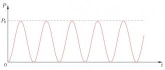
With alternating current, the direction and magnitude change cyclically over time. The cycle of one complete change (oscillation) is called period (T) , and its inverse value is called frequency (f) . The letter designation of alternating current is AC , an abbreviation for Alternating Current (alternating current), and graphically it is indicated by a sine wave segment:
̴
After this sign the voltage is indicated, sometimes the frequency and number of phases.
Alternating current is characterized by the following parameters:
| Characteristic | Designation | Unit | Description |
| Number of phases | Single phase | ||
| Three-phase | |||
| Voltage | U | volt | Instantaneous value |
| Amplitude value | |||
| Effective value | |||
| Phase | |||
| Linear | |||
| Period | T | second | Time of one complete oscillation |
| Frequency | f | hertz | Number of oscillations per second |
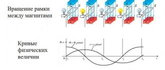
Single-phase current in its pure form is obtained using gasoline and diesel generators. In other cases, it is part of a three-phase voltage, which consists of three voltages varying according to a sinusoidal law, evenly shifted relative to each other. This time shift is called the phase angle and is 1/3T.
Four wires are used to transmit three-phase voltages. One is their common point and is called zero (N), and the other three are called phases (L1, L2, L3) .
Three-phase AC voltage graphs
The voltage between phases is called linear , and between phase and zero - phase , it is √3 times less than linear. In our network, the phase voltage is 220 V, and the linear voltage is 380 V.
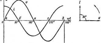
The instantaneous value of alternating current voltage is understood as its value at a certain point in time t. It changes with frequency f. The instantaneous voltage value at the maximum point is called the amplitude value. But this is not what voltmeters and multimeters measure. They show a value √2 times smaller, called the effective or effective voltage value . Physically, this means that a direct current voltage of this magnitude will do the same work as the measured alternating voltage.
Characteristics of three-phase current
Contents Previous § Next1.3. AC Conversion
to constant and constant to variable
Electricity is generated at power plants by synchronous generators, i.e. alternating current generators, which can be conveniently converted by transformers and transmitted over long distances. Meanwhile, there are a number of technological processes that require direct current: electrolysis, battery charging, etc. Therefore, there is often a need to convert alternating current to direct current and vice versa.
Widespread at the beginning of the 20th century. electrical machine converters (single-armature converters and motor-generator sets) have given way to more compact and silent semiconductor rectifiers. Thanks to high
Rice. 1.12. Push-pull single-phase rectifier
Due to the performance indicators and small dimensions of semiconductor rectifiers, there has been a tendency to replace DC generators with synchronous generators that have a semiconductor rectifier at the output. Thus, new classes of machines appeared - transformers and synchronous ones - constantly working with rectifiers. However, the operation of an electric machine on a rectifier has features that must be taken into account when designing these machines and analyzing the processes occurring in them.
AC Conversion
DC
is
produced using semiconductor valves having one-way conductivity.
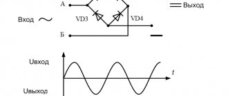
In Fig. Figures 1.12
and 1.13 show the most common rectifier circuits: single-phase (Fig. 1.12, a) and three-phase (Fig. 1.13, a) and voltage and current curves (Fig. 1.12.5.
c,
Fig. 1.13.6,
c
, respectively). Current can pass through semiconductor valves (diodes) only when a positive potential is applied to the anode (in the direction of the apex of the triangle in Fig. 1.12, a), and therefore the voltage across the load is pulsating.
Rice. 1.13. Three-phase bridge rectifier
With single-phase rectification, the voltage ripples across the load are very significant, and the frequency of the alternating component is 2 times higher than the frequency of the alternating current (Fig. 1.12, b). With three-phase bridge rectification, the circuit turns out to be six-cycle and the voltage ripple is small - less than 6% of the constant component (Fig. 1.13, b).
The current in the load circuit is usually smoothed more than the voltage, since the load circuit often contains inductance, which represents a large resistance for the alternating component of the current and a small one for the direct one.
If we consider the current in the load /<* to be completely smoothed, then a current in the form of rectangles passes through the windings of the transformer (Fig. 1.12.6 and 1.13, c),
containing higher harmonics that increase the heating of the windings.
In addition, when using rectification circuits with a zero point, there is a constant current component in the windings (Fig. 1.12.6). Because of this, the effective value of the current increases sharply and it is necessary to take measures against the creation of permanent magnetization of the rod. To prevent this phenomenon, for example, in single-phase transformers, either an armored
structure is used (Fig. 1.14), or all the windings of the transformer are placed on each rod, dividing them in half.
Great influence on the operation of the rectifier (Fig. 1.15,
o) has the effect of current switching - the process of switching from one valve to another.
Due to the presence of inductances in the current-carrying circuit and the inductance caused by the leakage fluxes of the transformer, the current from one valve does not transfer to another instantly, but over the commutation period Tk, which corresponds to the commutation angle y
(Fig. 1.15, b).
For simplicity, we assume that the load current Id
perfectly smoothed.
Then the sum of the currents through the first and second valves ia\
and
iai
during the switching process is unchanged:
Rice. 1.14. Schematic drawing of an armor transformer
At the moment of commutation, when the EMF value passes through zero and changes sign, the transformer winding becomes short-circuited and an equation can be written for its circuit
During switching, load voltage CLg = 0.5(e2a+ +e2b)
and in a single-phase rectifier it is equal to zero (Fig. 1.15,
b).
Consequently, due to commutation, the rectified voltage decreases and its ripple increases.
Since the commutation angle y is greater, the greater the load current Id
and the inductive reactance
xa,
to improve the quality of the rectifier, it is desirable that the machine feeding it have a small inductive reactance.
In a transformer, xa
is equal to the inductive reactance caused by leakage fluxes, and is determined from the experience of a short circuit in a synchronous generator
where is Ha"
and
xq"
are supertransient inductances along the longitudinal and transverse axes, respectively, taking into account the presence of current in the damper winding.
Thus, synchronous generators designed to operate on a rectifier must be designed to operate with non-sinusoidal current and have a damper winding.
The power factor of a generator operating on an unregulated rectifier is
Rice. 1.16. Single-phase inverter circuit
where v«0.9 is the distortion coefficient; >f«0.5y is the angle of current shift relative to the first voltage harmonic.
Converting DC to AC
produced using inverters that use controlled valves: transistors, thyristors, etc.
The circuit of a single-phase inverter is shown in Fig. 1.16. The inverter valves are switched on alternately every half-cycle so that the direction of the current in the secondary winding of the transformer is opposite to the direction of the EMF in this winding, i.e., so that energy is transferred from the direct current source to the alternating current network.
Inverters have a relatively complex automatic control system, which leads to an increase in their cost and a decrease in reliability compared to uncontrolled rectifiers.
In addition, a through combustion mode may appear in the inverter,
when the current in the winding is in phase with its EMF. This mode is possible either if there is a malfunction in the control system, or if the switching angle is too large. During through combustion, the current usually increases to an unacceptable value and usually the semiconductor valves fail. The large number of elements in the control system and the possibility of an emergency through-combustion mode make the reliability of inverters significantly lower than that of uncontrolled rectifiers: the time between failures is reduced by 50... 100 times.
The idea of powering asynchronous and synchronous motors from inverters is promising. By changing the switching frequency of the valves, you can change the frequency of the voltage at the motor stator terminals and thereby economically (without resistance) regulate the angular speed. This method of speed control is called frequency control. However, the low reliability of systems with inverter-frequency converters prevents their widespread use.
Currently, frequency variable speed control is used only in special conditions where DC motors immersed in liquid cannot operate: ship engines, oil pipelines, ball mill motors, etc.
Rice. 1.17. Design of a DC machine
There are experimental samples with frequency regulation in crane and traction electrical equipment.
A DC machine has a kind of converter—a collector, which is a rectifier in generator mode, and a frequency converter in motor mode.
The design of a direct current machine is similar to the design of an inverted synchronous machine, in which the armature winding is located on the rotor and the magnetic poles are stationary. When the armature (rotor) rotates, an EMF is induced in the winding conductors, directed as shown in the cross section in Fig. 1.17, a.
In conductors located on one side of the line of symmetry separating the poles, the emf is always directed in one direction, regardless of the angular velocity. During rotation, some conductors go under the other pole, other conductors take their place, and in space, under a pole of one polarity, the picture is almost motionless, only some conductors are replaced by others. Therefore, it is possible to obtain a practically constant EMF from this part of the winding.
Constant EMF is obtained using sliding contact between the winding and the external electrical circuit.
The conductors are connected in turns with a pitch of usht,
as in AC machines, and then the turns are connected in series one after the other, a closed winding is formed.
In half of the winding (in a two-pole machine), an EMF of one sign is induced, and in the other - of the opposite sign, as shown in the equivalent winding diagram (Fig. 1.17, b).
Along the contour of the winding, the EMF in its parts is directed counter and mutually balanced. As a result, when the generator is idling, i.e., in the absence of an external load, no current passes through the armature winding.
The external circuit is connected to the armature through brushes installed on the geometric neutral.
To improve contact, the brushes are made in the form of rectangular graphite bars, and they slide over the surface of the commutator, which is assembled from copper plates isolated from each other.
In large machines the beginning and end of each turn are connected to the commutator plates; in small plate machines
less than the number of turns, and therefore a part of the winding of several turns is soldered between the two plates - a section.
Under load, a current passes through the armature conductors, the direction of which is determined by the direction of the emf.
Due to the fact that the load current is constant, in the turns of the armature winding the current has a shape close to rectangular (Fig. 1.18, a).
When a turn passes from one parallel branch to another, it is short-circuited by a brush for a time called the commutation period
(Fig. 1.18, b)
TK=bJvKOn,
(1.66)
where bsh
— brush width; iKol is the linear velocity of a point located on the surface of the collector.
In the simplest case, when the brush is narrower than the collector plate, for the section closed by the brush (Fig. 1.18.0),
Rice. 1.18. Switching current diagrams
where iiRi=AUi
and
i2R2=AU2
- voltage drop in the brush contact with the first and second collector plates, respectively;
Rc
is the active resistance of the section;
Lpe3 is the resulting inductance of the section; ek
- EMF from the external field.
Neglecting iRc
due to the smallness
of Rc,
we obtain
The resulting basic commutation equation
(1.68)
coincides with the commutation equation in the rectifier
(1.61). The solution to this equation is easy to obtain by assuming that ΔΕΛ - Δε/2«0,
So that when the first plate leaves the brush, there is no current break, at time t = TK
the current through the first plate should be equal to zero: 11(Gk)=0=21a-|-ek.sr71k/^res, whence
This condition for sparkless commutation is reduced to the fact that in all modes the commutation angle y
was unchanged:
y=*TK=2vJ>JDavKoll=2b'jDa,
(1.71)
where Da
- anchor diameter;
va is
the linear speed of a point located on the surface of the anchor;
b'shch = bshchOa/OKol
- the width of the brush reduced to the diameter of the armature.
To fulfill this condition, the EMF in the commutation zone EMF ek
is created by special additional poles, the winding of which is connected in series to the armature circuit, and their magnetic circuit is made unsaturated.
The switching process in rectifiers, inverters and DC machines is similar. In both cases, the process of changing the current during the switching period is determined by the value and shape of the EMF in the short-circuited circuit. Therefore, one cannot liken the collector to a mechanical rectifier, as is sometimes done [3].
The presence of a collector also introduces its own characteristics: the design of the machine becomes more complicated and operation becomes more expensive. However, these disadvantages of electric machines are compensated by their main advantage: in motor mode, random commutation failures usually lead to slight burnout of the commutator and brushes, and not to an emergency rollover mode,
as in inverters.
As a result, the reliability of a DC commutator machine is much higher than the reliability of the “asynchronous motor-frequency converter” system, its efficiency is 3...5% higher, the machine is much cheaper, has smaller dimensions and weight.
These advantages make it necessary to give preference to a DC machine, limiting the use of an asynchronous motor with frequency regulation to the narrow scope of specific devices (motors operating in liquids, etc.).
Contents Previous § Next
Advantages and disadvantages of alternating voltage
So why did they choose alternating current rather than direct current for power supply?
When transmitting electricity, current passes through wires hundreds of kilometers long, heating them and dissipating energy into the air. This is inevitable for both direct and alternating currents. But the power loss depends only on the resistance of the wires and the current in them:
The power transmitted along the line is equal to:
It follows that as the voltage increases, less current is needed to transmit the same power, and the power loss decreases. This is why the voltage is increased on long power lines. There are lines for 6kV, 10kV, 35kV, 110kV, 220kV, 330kV, 500kV, 750kV and even 1150kV.
But in the process of transferring electricity from source to consumer, the voltage must be changed repeatedly. It is easier to do this on alternating current using transformers.
The disadvantages of alternating current appear when transmitting energy through cable lines. Cables have capacitance between phases and with respect to ground, and the capacitance conducts alternating current. A leak appears, heating the insulation and causing it to fail over time.
Types of inverters
Inverters can be classified according to several criteria. One of them is the shape of the received signal. Inverters are capable of producing:
- Square wave signals.
- Stepped shape. In this case, the DC voltage is processed in two stages. First, unipolar pulses of the desired type and double frequency are formed. Then, using a bridge converter, a multipolar signal with the necessary characteristics is obtained.
- Sinusoidal shape. In this case, a high-frequency signal of the same amplitude is first obtained. Special modulation is then performed repeatedly using a bridge inverter.
Converting AC to DC and vice versa
The process of obtaining direct current from alternating current is called rectification , and the devices are called rectifiers . The main part of the rectifier is a semiconductor diode , which conducts current in only one direction. As a result of rectification, a pulsating current is obtained, changing its value over time, but not changing its sign.
Then the ripples are eliminated using filters , the simplest of which is a capacitor . It is impossible to completely eliminate ripple, and its final level depends on the rectifier circuit and the quality of the filter. The complexity and cost of rectifiers depends on the magnitude of the output ripple and the maximum output power.
Diagram of a simple rectifier Rectifier operation graphs
Inverters are used to convert to alternating current . The principle of their operation is to generate an alternating voltage with a shape as close as possible to a sinusoidal one. An example of such a device is a car inverter for connecting household appliances or tools to the on-board network.
The better and more expensive the inverter, the greater its power or more accurately the voltage it produces approaches a sine wave.
Rate the quality of the article:
How to make a straightener yourself
If you independently create a device that converts alternating voltage, you can not only get out of a difficult situation, but also better understand the principle of its operation. To work you need to prepare the following:
- A device that can be used to measure voltage. For this, for example, you can use a voltmeter or multimeter.
- Insulating tape, keeper tape.
- Copper wire.
- Soldering iron.
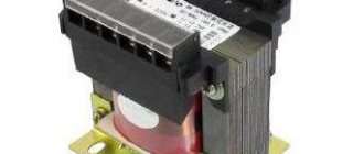
- Transformer. Buy one whose primary winding is designed for 220 V.
Having prepared everything you need, you can start working:
- First you need to connect the transformer to the network and measure the voltage on the secondary winding. If, for example, you want to get 12 volts after rectification, then you will have to remove some of the turns.
- Then you should solder the diode bridge and capacitor in accordance with the rectifier circuit diagram.
It must be taken into account that compared to the alternating voltage on the secondary winding, the result at the output terminals will increase by 1.41 times. That is, to obtain 12 V it is necessary that the variable be equal to 8.51 V (12/1.41 = 8.51).
Here we tell you how to make a simple rectifier, but in practice other options are also used. For example, a voltage doubling rectifier. The principle of its operation is based on the alternate charging and discharging of capacitors by input voltage with half-waves of different polarities. The result is a voltage twice the input voltage.
A doubler is used when there is a need to double the voltage drawn from the secondary winding of the transformer. This option is more cost-effective than rewinding the winding.