The brilliant inventor Thomas Edison bet on direct current and lost. But today a constant stream is looking for new champions.
Thomas Edison is considered one of the greatest inventors in history. As the creator of such inventions as the phonograph and the light bulb, he has 1,093 patents to his name. Edison launched his first power plant in 1882, which, among other things, provided electricity to Wall Street in New York. The power plant used direct current.
At the same time, Edison's employee Nikola Tesla successfully developed the dynamo. But the Croatian scientist had a different idea. Instead of direct current, Tesla focused on developing alternating current. After his dispute with Edison, Tesla continued his work with Edison's rival George Westinghouse. Alternating current showed obvious advantages. For long distance transmission, the voltage can be easily adjusted using transformers. The cable used may also be thinner and therefore cheaper. Instead of recognizing these advantages and supporting alternating current, Edison insisted on his own and tried to discredit his competitors. Edison claimed that the newly invented electric chair was equipped with the technology of his rivals. His message was simple: alternating current is doomed. Although his campaign was successful, Edison's victory did not last long. The 1893 Chicago World's Fair featured alternating current equipment, presaging the 20th century's electrical revolution.
Thomas Edison later confessed to his son: “I think the moment I refused to support alternating current was the biggest mistake of my life.”
What is electric current
The movement of free carriers of electric charges in a vacuum or substance in a fixed direction is called electric current. Free carriers in metals are electrons, in liquids or gases they are ions. The name "current" has two interpretations. The first one denotes the very movement of the electric charge in the conductor, the second one – an estimate of the number of electrons passing through the conductor in 1 s. Its strength can be determined by Ohm's Law. The formula used for this is:
I=U/R,
where U is voltage, V; R – resistance, Ohm.
Scheme
Half-wave rectifier. The simplest circuit with a minimum number of elements. The quality of the rectified voltage is low.
Single-phase half-wave rectifier circuit
Full-wave rectifier, midpoint circuit. The pulsation level U in this case is lower compared to the previous option.
Full-wave rectification circuit with midpoint
Full-wave rectifier, bridge circuit. The most popular option for industrial equipment. The circuit uses 4 diodes. The RC filter installed at the output smoothes out voltage ripples. It is often replaced by an electrolytic capacitor.
Full-wave bridge rectifier circuit
DC and AC current
The socket has direct or alternating current
Electrons in conductors move from plus to minus. The movement is uniform, always with a constant value. If you ask yourself what currents are considered constant, you first need to have a good idea of where the current flows.
Attention! The direction of current is considered to be the direction in which positively charged particles move: from plus to minus. Although the path of free electrons runs from minus to plus.
DC direction
This means that direct current is the directed movement of charged particles that carry a positive charge and do not change their magnitude and direction over time. All other currents are variable. This is their difference.
Alternative Current – AC, this is how alternating current is designated on devices. Direct Current – DC is a clear designation for direct current.
Direct and alternating current
Electrical voltage is divided into two types:
- constant (dc)
- variable (ac)
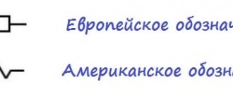
The designation for direct current is (—), for alternating current the designation is (~). The abbreviations ac and dc are well-established and are used along with the names “constant” and “variable”. Now let's look at what is their difference. The fact is that constant voltage flows only in one direction, which is where its name comes from. And a variable, as you already understood, can change its direction. In particular cases, the direction of the variable may remain the same. But, in addition to the direction, its magnitude can also change. In a constant, neither magnitude nor direction changes. The instantaneous value of alternating current is its magnitude, which is taken at a given moment in time.
In Europe and Russia, the accepted frequency is 50 Hz, that is, it changes its direction 50 times per second, while in the USA, the frequency is 60 Hz. Therefore, equipment purchased in the United States and in other countries may burn out with different frequencies. Therefore, when choosing equipment and electrical appliances, you should carefully ensure that the frequency is 50 Hz. The higher the frequency of the current, the greater its resistance. You can also notice that in the sockets in our house it is AC that flows.
It will be interesting➡ Arduino for beginners
In addition, alternating electric current is divided into two more types:
- single-phase
- three-phase
For single-phase, a conductor is required that will conduct voltage and a return conductor. And if we consider a three-phase current generator, it produces an alternating voltage with a frequency of 50 Hz on all three windings. A three-phase system is nothing more than three single-phase electrical circuits, out of phase relative to each other at an angle of 120 degrees. Through its use, it is possible to simultaneously provide energy to three independent networks, using only six wires that are needed for all conductors: forward and reverse, to conduct voltage.
And if you, for example, have only 4 wires, then there will be no problems either. You will only need to connect the return conductors. By combining them, you get a conductor called neutral. It is usually grounded. And the remaining external conductors are briefly designated as L1, L2 and L3.
But there is also a two-phase one, it is a complex of two single-phase currents, in which there is also a direct conductor for conducting voltage and a reverse one, they are shifted in phase relative to each other by 90 degrees.
Current differences
Ignorance of the differences leads to incorrect connection of voltage consumers to power supplies. This causes damage to appliances or worse, life-threatening situations.
Lethal current for humans
To clearly understand which current is called alternating and which is constant, you need to compare the parameters.
When comparing the characteristics of these two types of electricity, the differences are distinguished:
- Physical - with alternating current, the strength and direction depend on time. In a household network, the pulsation frequency is 50 Hz. The polarity changes in a sine wave 50 times per second. Direct current charge carriers do not change direction.
- Constructive - DC has “+” and “–” on its terminals or contacts, while AC has “zero” and “phase” on its electrodes. In the case of a three-phase network, there are 4 contacts: one “zero” and three “phase”.
- The principle of generation is that direct current is obtained as a result of electrolytic and chemical oxidation reactions, the operation of direct current generators and solar panels. Alternating current is produced by three-phase generators.
- In conversion - both types are obtained by converting one into the other using semiconductor rectifiers and inverters.
For information. There are two main standards for frequency and voltage in the consumer AC network in the world. The European standard is 50 hertz, 220-240 volts, and the American standard is 60 hertz, 100-127 volts.
Advantages of AC
AC symbol
Rechargeable batteries are practical as a source of constant electricity. However, they cannot endlessly supply current collectors with energy without recharging. Therefore, the creation of time-varying current and its delivery to the consumer are the main tasks of the country’s power system. The advantages of this type include:
- ease of conversion from one voltage value to another;
- permissibility of long-distance transmission via power lines to distribution networks;
- the ability to implement three-phase power supply schemes;
- focus on consumers of production enterprises designed for alternating current power supply.
It is easier to reduce or increase the AC voltage value. To do this, you just need to pass it through a transformer. The high efficiency of this converter is 99%, power loss is only 1%. The transformer, having separate voltage windings, also separates high voltage from low, which makes it possible to separate installations up to 1000 V and over 1000 V.
Nuclear and hydroelectric power plants are located in places remote from the central areas where consumers are located. Therefore, the voltage of the extracted electricity is increased to hundreds of kW in order to reduce losses during transportation, and transmitted via power lines to the desired location, where it is lowered again.
Hydroelectric power station - hydroelectric power station
By using three-phase alternating voltage, the performance of the power system structure is increased. Transmitting the same power in a three-phase network requires fewer conductors, unlike a single-phase line.
Important! If we compare two transformers of the same power, then the dimensions of a single-phase transformer are larger than those of a three-phase one. Asynchronous motors are cheaper to manufacture than DC motors. They do not have a commutator and brushes; in terms of power, with the same dimensions, asynchronous motors are 2-3 times faster than constant motors.
What happens if you apply direct current to the power grid?
The war of currents is over, and Tesla and Westinghouse seem to have won. DC networks are now used in some places on the railway, and also in the form of ultra-high-voltage transmission lines. The vast majority of power grids operate on alternating current. But let's imagine that instead of an alternating voltage with an effective value of 220 volts, the same 220 V, but direct current, suddenly began to flow into your house. The theater begins with a hanger, and our electric circus begins with the opening panel.
And immediately there is good news: the circuit breakers will work as expected. The machine has two releases: thermal and electromagnetic. Thermal serves to protect against prolonged overload. The current heats the bimetallic strip, it bends and opens the circuit. The electromagnetic element is triggered by a short-term current pulse during a short circuit. It is a solenoid that draws the core into itself and, again, breaks the circuit. Both of these systems work great on DC.
image source: switch-automatic.rf
Additions from Bronx and AndrewN: The magnetic release is triggered by the amplitude value of the current, that is, 1.4 times more than the current one. At direct current, its operating current will be 1.4 times higher.
A DC arc is more difficult to extinguish, so in the event of a short circuit, the circuit breaking time will increase and the wear of the machine will accelerate. There are special machines designed to operate with direct current.
In addition to the automatic machines, the panel has a residual current device (RCD). Its purpose is to detect current leakage from the network to the ground, for example when a person touches live parts. An RCD measures the current in two conductors passing through it. If the same current flows into the load as flows out, everything is in order, there is no leakage. If the currents are not equal, the RCD sounds the alarm and breaks the circuit.
The sensitive element of the RCD is a differential transformer. Such a transformer has two primary windings connected in opposite directions. If the currents are equal, their magnetic fields cancel each other and there is no signal at the output. If the currents are not compensated, a voltage appears at the output of the signal winding, to which the RCD circuit reacts. The transformer will not work on direct current, and the RCD will be useless.
It doesn’t matter what kind of electric meter you have - an old mechanical one or a new electronic one - it won’t work. A mechanical meter is an electric motor where the rotor is a metal disk and the stator contains two windings. One winding is connected in series with the load and measures current, the second is connected in parallel and measures voltage. Thus, the greater the power consumption, the faster the disk spins. The operation of such a counter is based on the phenomenon of electromagnetic induction, and with a constant current in the windings, the disk will remain motionless.
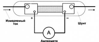
The electronic meter is designed differently. It directly measures voltage (via a resistive divider) and current (using a shunt or Hall sensor), digitizes them, and then the microprocessor converts the resulting data into kilowatt-hours. In principle, nothing prevents such a circuit from working with direct current, but in all household meters the direct component is filtered out by software and does not affect the readings. DC meters exist in nature; they are installed, for example, on electric locomotives, but you won’t find one like this in an apartment panel.
Well, okay, it wasn’t enough to pay for all this disgrace! Let's go further along the chain and see what electrical appliances we might encounter.
Everything is fine here. An electric heater is a purely resistive load, and the thermal effect of the current does not depend on its shape and direction. Electric stoves, kettles, boilers, irons and soldering irons will work on direct current in the same way as on alternating current. Bimetallic thermostats (such as those in an iron) will also function correctly. The good old Ilyich light bulb feels no worse on direct current than on alternating current. Even better: there will be no light pulsations, the lamp will not buzz. On alternating current, the light bulb may hum due to the fact that the spiral (especially if it is sagging) works like an electromagnet, compressing and stretching twice per period. When powered by direct current, this unpleasant phenomenon will not occur.
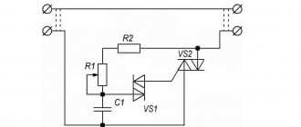
However, if you have brightness controls (dimmers) installed, they will stop working. The key element of a dimmer is a thyristor - a semiconductor device that opens and begins to pass current at the moment a control pulse is applied. The thyristor closes when the current stops flowing through it. When the thyristor is powered with alternating current, it will close whenever the current passes through zero. By applying a control pulse at different times relative to this transition, you can change the time during which the thyristor will be open, and therefore the power in the load. This is exactly how a dimmer works.
When powered by DC, the thyristor will not be able to close, and the lamp will always burn at 100% power. Or perhaps the control circuit will not be able to “catch” the transition of the mains voltage through zero and will not provide an impulse to open the thyristor. Then the lamp will not light up at all. In any case, the dimmer will be useless. A fluorescent lamp cannot be connected directly to the network; for normal operation it needs a ballast (ballast). In the simplest case, it consists of three parts: a starter, a choke and a capacitor. The latter is needed not by the lamp itself, but by other consumers in the network, as it improves the power factor and filters the interference created by the lamp. A starter is a neon light bulb, one of the electrodes of which, when heated, bends and touches the second electrode. The inductor is a large inductor connected in series with the lamp:
Normally, it all works like this: when turned on, the discharge in the starter lights up, its contacts heat up and close together. Current flows through the filaments of the lamp, causing them to heat up and begin to emit electrons. At this time, the starter cools down and opens the circuit. The current drops sharply, and due to self-induction, a high voltage pulse appears at the inductor. This impulse ignites a discharge in the lamp, and then it burns on its own. The choke now limits the discharge current, working as an additional resistance.
What will happen with direct current? The starter will work, the lamp will light up as expected, but then everything will go wrong. In a DC circuit, the inductor will have no inductive resistance (only the active resistance of the wires, and it is small), which means it will no longer be able to limit the current. The higher the discharge current, the more the gas in the lamp is ionized, the resistance drops, and the current increases even more. The process will develop like an avalanche and end with the explosion of the lamp.
Electromagnetic ballasts are simple, but not without their drawbacks. They have low efficiency, the choke is bulky and heavy, it hums and gets hot, the lamp lights up with wild blinking, and then flickers at a frequency of 100 Hz. The electronic ballast (EPG) does not have all these shortcomings. How does he work? If you look at the diagrams of various electronic ballasts, you will notice a general principle. The mains voltage is rectified (converted to direct), then a generator using transistors or a microcircuit generates a high-frequency alternating voltage (tens of kHz), which powers the lamp. Expensive electronic ballasts have filament heating and soft start circuits that extend the life of the lamp.
image source: aliexpress.com
Both blocks for linear lamps and compact “energy savers” that are screwed into a regular socket have similar circuitry. Since there is a rectifier at the input of the electronic ballast, the entire circuit can be powered with a constant voltage.
The LED requires a small constant voltage to operate (about 3.5 V, usually several diodes are connected in series) and a current limiter. LED lamp circuits are very diverse, from simple to quite complex.
The simplest thing is to place a quenching resistor in series with the LEDs. The excess voltage will drop across it, and it will also limit the current. This circuit has a monstrously low efficiency, so in practice a quenching capacitor is installed instead of a resistor. It also has resistance (for alternating current), but it does not dissipate thermal power. The cheapest lamps are assembled according to this scheme. The LEDs in them flicker at a frequency of 100 Hz. Such a lamp will not work on direct current, since for direct current the capacitor has infinite resistance.
image source: bigclive.com
More expensive lamps are more complex, very similar to electronic ballasts for fluorescent lamps. The power source in them contains a high-frequency switching stabilizer, which is powered by rectified mains voltage. As with electronic ballasts, the circuit will work normally if a constant voltage is applied to it.
picture source: powerelectronictips.com
A universal commutator motor (UCM) consists of a stationary stator and a rotor that rotates internally. The stator has one winding, and the rotor has several. The rotor windings are connected through a commutator - a cylinder with contacts along which carbon brushes slide. The interaction of the magnetic fields of the stator and rotor causes the rotor to turn. The collector is designed in such a way that it always turns on the one of the windings that is perpendicular to the stator winding - for it the torque will be maximum.
Such a motor can operate when powered by both alternating and direct current. Actually, that’s why it’s called “universal”. When the polarity changes, the direction of the magnetic field in both the stator and the rotor simultaneously changes, as a result the motor continues to rotate in the same direction. At direct current, the UCD develops even more torque than at alternating current, due to the absence of inductive resistance of the windings. Universal commutator motors are used where it is necessary to obtain high power with small dimensions. In household appliances, UKDs are found in washing machines, vacuum cleaners, hair dryers, blenders, mixers, meat grinders, and also in power tools. All of these devices will continue to work if the voltage at the outlet suddenly “straightens out.” A synchronous motor has several windings in the stator that create a rotating magnetic field. The rotor contains a permanent magnet or a winding powered by direct current. The magnetic field of the stator meshes with the field of the rotor and rotates it behind itself. A special feature of such a motor is that its rotation frequency depends only on the frequency of the supply current. At direct current, obviously, such a motor will rotate at zero frequency, that is, it will stop.
In everyday life, low-power synchronous motors are used where it is necessary to maintain a strictly constant rotation speed. Basically, these are electromechanical clocks and timers. The plate rotation motor in a microwave oven and the drain pump motor in a washing machine are also synchronous. An asynchronous motor is similar in design to a synchronous one. It also has a stator with several windings and creates a rotating field. But the rotor winding is not connected anywhere and is short-circuited. The current in it is created due to the phenomenon of electromagnetic induction in the alternating field of the stator. This current creates its own magnetic field, which interacts with the rotating field of the stator and causes the rotor to rotate.
Asynchronous motors are characterized by low noise levels and long service life due to the absence of rubbing brushes. They can be found in refrigerators, air conditioners and fans. When powered by direct current, the magnetic field of the stator will not rotate. Also, no current will arise in the squirrel-cage rotor. The motor will remain motionless, and the winding will simply heat up, like an ordinary piece of wire. Strictly speaking, this is not a separate type of engine, but a way of controlling it. The motor itself can be synchronous or asynchronous. The main feature is that the voltages on the windings are generated by the control circuit based on a signal from the rotor position sensor. This allows you to regulate speed and torque over wide ranges, limit starting currents and provides a bunch of possibilities, such as stabilizing the rotation speed. Here are a couple of good articles that explain all this magic:
One Two
Fan motors are increasingly used in household appliances: washing machines, refrigerators, air conditioners, vacuum cleaners. Typically, such equipment can be recognized by the adjective “inverter” in advertising. The valve motor is indifferent to the shape of the supply voltage. The network voltage is first rectified, and then the control unit “sculpts” from it several different sinusoids (usually three) to power the motor windings. Naturally, such a system will operate quietly on direct current. A transformer consists of several windings connected by a common magnetic core. Alternating current in one winding (primary) generates induced currents in all other windings (secondary). The key feature of a transformer, for which it is usually used, is that the voltages on the windings are related in the same way as the number of turns in these windings. If you wind 1000 turns in the primary winding and 100 turns in the secondary, such a transformer will reduce the voltage by 10 times. If you turn it on the other way around, it increases 10 times. Very simple and convenient.
In a linear power supply, the mains voltage is reduced (or raised, if necessary) to the required level using a transformer. Next is a rectifier that converts alternating voltage to direct voltage, and a filter that smoothes out ripples. Then there can be a stabilizer that keeps the output voltage constant.
Linear power supplies are gradually being replaced by switching ones, but the former still work in many places. In a microwave oven, if it is not an “inverter” one, there is a powerful transformer that increases the 220 V network to several kilovolts necessary for the operation of the magnetron. Transformers power the control electronics in washing machines, cookers and air conditioners. Transformer power supplies are used in audio equipment and cheap chargers.
What happens to a transformer if it is connected to a DC network? Firstly, voltage will not appear on the secondary windings, since electromagnetic induction occurs only when the current changes. Secondly, the winding will not have inductive reactance, which means that much more current will flow through it than calculated. The transformer will overheat and burn out quite quickly.
The higher the frequency of the alternating current, the more efficiently the transformer operates (within reasonable limits, of course). If you use a frequency of several tens of kilohertz instead of the network 50 Hz, you can significantly reduce the dimensions of transformers with the same transmitted power. This idea is the basis of switching power supplies. Such a unit works as follows: the network voltage is rectified, the resulting direct voltage feeds a transistor generator, which again produces alternating voltage, but at a high frequency. It can now be lowered or raised by a transformer, rectified and fed into the load.
This circuit now powers the vast majority of electronics: computers, monitors, televisions, chargers for laptops, phones and other gadgets. Since the input voltage is rectified first, the switching power supply should operate on DC without any problems. But there are a couple of moments that can ruin everything.
Firstly, the voltage after the rectifier is almost equal to the amplitude value of the alternating voltage. That is, for ~220 V at the input, the rectifier will give 311 V. According to the condition, we supply a constant voltage of 220 V, which is 30% lower. This will likely not cause problems because modern power supplies can operate over a wide range of voltages, typically 100 to 250 V.
Secondly, the rectifier consists of four diodes that work in pairs: one pair on the positive half-wave of the current, the other on the negative. Thus, each diode passes current only half the time. If we apply a constant voltage to the rectifier, one pair of diodes will always be open, and double power will be dissipated on them. If the diodes do not have double the current capacity, they may burn out. But this is not too big of a problem: you can simply throw out the rectifier and apply constant voltage immediately after it.
After you've put out a few fires and raked up the damaged appliances, it's time to take stock. The transition to direct current will survive either old and simple equipment (incandescent lamps, heaters, mechanically controlled brushed motors) or, conversely, the most modern (with switching power supplies and inverter motors).
Fortunately, the described scenario is unlikely to come true in practice, unless the possibility of specially organized sabotage is considered. In case of any possible accident in the power grid, the alternating voltage will suddenly become constant. True, in possible accidents other bad things happen, but that’s a completely different story. Take care of yourself and make backups.
Disadvantages of DC
In addition to the fact that sources of this type of current have a complex design, they are more difficult to operate. With an efficiency of 94%, the maximum power of these machines is no higher than 20 MW. There are also other disadvantages:
- complex circuits are used to increase or decrease voltage;
- motors designed to consume such electricity are also structurally complex and expensive;
- decoupling low and high voltage requires complex solutions.
It is not possible to completely abandon such sources and consumers, since they are in demand and have their own advantages.
Disadvantages of AC
When transmitting the energy of a current changing direction over long distances, difficulties arise. The creation of the Unified Energy System revealed a number of shortcomings:
- the capacity of cable lines is low due to the capacitance between the conductors and the ground;
- when merging and looping system branches located at large distances from each other, it is impossible to synchronize stations;
- The threshold stability limit required for coordination ends at line lengths exceeding 500 km, which requires an increase in voltage to 450 kV, which leads to an increase in the cost of terminal equipment.
For your information. When the voltage increases, a corona discharge occurs near the overhead lines. This is the process of ionization in conductors with a small radius. To prevent electricity from draining in this case, it is necessary to increase the diameter of the wires, this leads to an increase in the cost of the line.
Advantages of DC
What qualities make direct current irreplaceable? The advantages include:
- there is no reactive power in the circuits, which leads to losses;
- There is no need to synchronize generators running in parallel;
- increased range of energy transmission in large volumes;
- safety for humans in contact with live conductors.
Added to the advantages is that electricity, such as direct current, flows across the entire cross-section of the conductor, so power losses are minimal.
Charge density over the cross section of the conductor
Current source operation
By moving electric charges along a section of a circuit, electric current does work. It consists of the work of Coulomb forces and the work of external forces:
A = Shark + Astor.
The work of a source is the work of external forces to transfer electrical charges along a conductor over time:
Stork = Astor = ε * I * t,
Where:
- ε – emf (V);
- I – current (A);
- t – time (s).
The work of electric current determines the degree of conversion of electricity into its other forms.
The history of the appearance and “war of currents”
Nikola Tesla and Thomas Edison did not live to see the moment when a representative of the Consolidated Edison company put an end to the struggle between the two technologies. Alternating electric current won the day. In 2007, the company's lead engineer disconnected the cable representing New York City's DC power.
Back in 1882, Serbian scientist Nikola Tesla figured out how to apply the effect of a rotating electromagnetic field. At that time, Edison had already commissioned 2 power plants generating direct current, and organized the production of cables, lighting devices and dynamos. Tesla at one time worked for Edison's company and repaired DC machines. Edison promised Nikola to pay for engine modernization projects, but refused to pay remuneration for the work done. Tesla sold the patents of his inventions to George Westinghouse, president of Westinghouse Electric Corporation, for $1 million. The first power plant with 500 V of polarity-changing electricity was launched in 1886. The war of currents continued for more than a century.
Continuous movement of electrons
Direct current is the continuous movement of electrons through a conductive material such as a metal wire. Charged particles move toward a positive (+) potential. To create the flow of electricity, an electrical circuit consisting of a DC power source and a wire is required to form a closed loop. A good example of such a circuit is a flashlight.
Although negatively charged electrons move through the wire to the positive (+) terminal of the power source, the flow of current is indicated in the opposite direction. This is the result of a failed and confusing agreement. Scientists experimenting with currents believed that electricity moves from (+) to (-), and this became generally accepted even before the discovery of electrons. In reality, negative charged particles move towards the positive pole, opposite to the direction indicated as the direction of current flow. It's confusing, but once an agreement has been made, it's hard to fix anything.
Sources of direct electric current
To obtain it, a special generator is used, the operation of which is based on the law of electromagnetic induction - EMF. If you rotate a metal frame, an EMF will arise in the area of the electromagnetic field, and electricity will flow through the frame.
DC generator
Attention! An increase in EMF is obtained by increasing the field strength or frame rotation speed. Reducing the pulsation of the resulting movement of electricity is achieved by adding the number of frames.
Non-mechanical producers of electricity of a constant nature:
- solar panels;
- galvanic cells;
- thermochemical elements.
Energy batteries from this group have a limited lifespan and require periodic recharging.
DC power supplies
Chemical current source
Chemical DC power supplies are a family of devices and apparatus that produce voltage at their terminals as a result of internal chemical processes of oxidation or galvanization. Their work is based on the reactions of chemical substances, which, when interacting with each other, produce a constant electric current.
For your information. Processes occurring in chemical sources (CHS) occur without thermal or mechanical influences. This sets them apart among devices that generate voltages of constant polarity.
Some types of chemical current sources
Terms and definitions are described in detail in GOST R IEC 60050-482-2011, which came into effect on July 1, 2012. It abbreviates chemical current sources - HIT.
The division by type of chemical insulation is carried out in the following gradation:
- primary;
- fuel;
- batteries.
This distinction is made by the mode of action of the source.
Chemical current sources
Single use items are primary sources. They contain a finite supply of reagents that will react and stop producing energy at the end of the process. These are various AA batteries.
Fuel HITs are capable of operating continuously, but require the supply of a new dose of substances and the removal of waste products. Essentially, this is a galvanic cell into which fuel and oxidizer are supplied separately and react at two electrodes. The fuel dissolves in the electrolyte and cathodic oxidation occurs. It is a virtually precision laboratory process.
Fuel cell operation diagram
Secondary cells that can be used many times after being recharged or recharged are called batteries. If current is connected to such devices, they are regenerated again and accumulate energy. They have found the widest application in powering mobile devices and mechanisms.
Battery power source
Application
Use in electronics to power circuits is not the end use case for DC. Direct current has found use in the following cases:
- in electrolysis – production of metals from salts and solutions on an industrial scale;
- galvanoplasty and galvanization - metal coating of electrically conductive surfaces;
- in welding work – work with stainless steel;
- in transport - engines of trams, electric locomotives, trolleybuses, icebreakers, submarines;
- in medicine – the introduction of drugs into the body through electrophoresis.
For information. In the USSR, the electrification of the railway with direct current began on the sections of Baku - Suramsky Pass and Sabuchini. Before the Great Patriotic War, the voltage was 1.5 kV, then it was transferred to 3 kV. In total, half of the railway lines operated from this type of current.
Alternating current
Forced harmonic electromagnetic oscillations are a sinusoidal current. Oscillations occur at a frequency of 50 Hz per second. The voltage and current per period are on average zero.
How does direct current differ from alternating current, and what is its path from source to consumer?
Direct current does not oscillate; this is where direct and alternating current differ. The supply of Direct Current - DC to consumers also occurs through wires and cables. The Volgograd-Donbass power lines are still in operation.
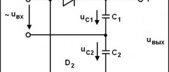
Dependence of voltage ripple on capacitor capacitance
Let's take a practical look at why we need to install a large capacitor. In the photo below we have three capacitors of different capacities:
Let's look at the first one. We measure its nominal value using our LC meter. Its capacity is 25.5 nanoFarads or 0.025 microFarads.
We connect it to the diode bridge according to the diagram above
And we cling to the oscilloscope:
Let's look at the oscillogram:
As you can see, the pulsations still remain.
Well, let's take a capacitor with a larger capacity.
We get 0.226 microfarads.
We connect it to the diode bridge in the same way as the first capacitor and take readings from it.
And here is the actual oscillogram
Not... almost, but still not the same. The pulsations are still visible.
Let's take our third capacitor. Its capacity is 330 microfarads. Even my LC meter cannot measure it, since my limit on it is 200 microfarads.
We hook it to the diode bridge and take an oscillogram from it.
And here she actually is
Here you go. It's a completely different matter!
So, let's draw some conclusions:
- the larger the capacitance of the capacitor at the output of the circuit, the better. But don’t overuse the capacity! Since in this case our device will be very large, because capacitors of large capacities are usually very large. And the initial charge current will be huge, which can lead to an overload of the supply circuit.
— the lower the resistance the load at the output of such a power supply is, the greater the ripple amplitude will appear. They combat this with the help of passive filters, and also use integrated voltage stabilizers, which produce the purest DC voltage.
Conversion
For household appliances that require circuits to be supplied with DC type electricity, it is supplied through power supplies. These are circuits that include a step-down transformer and a rectifying unit. When connecting the power supply to the device, make sure that their voltage and power parameters match. The parameters are indicated on the device body.
Mains power supply 50 Hz
At the moment, both types of electricity get along well in the modern world. Mixed nutrition schemes of consumers only complement each other.
Regulated Sources
The regulated source consists of the following components:
- a step-down transformer;
- rectifier;
- smoothing filter (eliminates ripples);
- DC voltage stabilizer.
DC voltage stabilizer is an integrated circuit that maintains the output voltage at the same level, regardless of its fluctuations at the input.
Fluctuations caused by voltage changes in the electrical network, changes in load current or temperature. Blocks with such stabilizers are called adjustable.
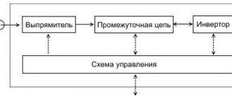
Switching power supplies are common today; they consist of the following components:
- input rectifier;
- inverter;
- step-down high-frequency transformer;
- output rectifier.
The inverter turns the pre-rectified current back into alternating current, but at the same time significantly increases its frequency - up to 10-15 kHz. At this frequency, the dimensions of the transformer and losses in it are significantly reduced. The inverter consists of key transistors controlled by a microcircuit.
The same principle is implemented in welding inverters, which explains their compactness.
There are many stabilizer microcircuits with different properties. For example, the LM317 chip is designed for a current of up to 1.5 A and allows you to adjust the output voltage. A more powerful stabilizer is the LM350 chip.
Video
Coffee capsule Nescafe Dolce Gusto Cafe O Le Coffee with milk, 3 packs of 16 capsules each
1305 ₽ More details
Coffee capsules Nescafe Dolce Gusto Café Au Lait, 16 pcs.
435 ₽ More details
Apple iPhone XR 128GB