In modern household networks, a huge number of appliances and devices are powered by reduced voltage. As a rule, these are low-current devices that use 12 volts in their power circuit: gas heaters, hand-held power tools, portable and stationary lamps, children's toys and much more.
Due to their widespread use, ordinary people try to organize power for such devices on their own, so in this article we will look at how to get 12 Volts in various ways.
We get 12 Volts from 220
The most affordable power source with a practically unlimited power resource is a household AC voltage of 220 Volts. All that is needed to obtain 12 Volts is to lower, and, if necessary, convert the existing electrical quantity into a constant.
To do this, you can use one of several methods:
- using a transformer for step-down and a diode bridge for further rectification;
- using a quenching capacitor;
- without a transformer - using a resistor or semiconductor device.
Now let's look at each of the methods in more detail.
Method without transformer
If there is no transformer that could lower the network voltage to 12 Volts, you can get by with a regular resistor. The fact is that the voltage drop across a resistor connected in series to a load of 208 Volts will provide 12 Volts on the desired device, provided that the network is 220 Volts.
If the network voltage differs significantly, then the universal formula for calculating the value of the additional resistor will look like this:
R1 = Uc / I - Rн
Where
- R1 – resistance of additional resistor;
- RН – load resistance;
- I – current in the resistor and load circuit (you can take the passport value);
- UC – network voltage.
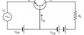
This method to get 12 Volts cannot be called justified, since the voltage drop across the resistor will lead to power consumption and additional energy costs. Therefore, another option for lowering the voltage level is to use thyristor or triac regulation. An example of such a scheme is shown in the figure below:
Reducing voltage using a triac
Here is a current-limiting circuit with capacitor C1 and resistors R1 and R2, which determine the time of charging the capacitance and sending a pulse through dinistor VS1 to the control electrode of triac VS2. This is a classic option for controlling the output voltage, which is often used in dimmers.
Using a Quenching Capacitor
In addition to the above methods, to get 12 Volts, you can use a circuit with a quenching capacitor.
Reducing voltage using a quenching capacitor
The figure above shows an example with two quenching capacitors C1 and C2, here both capacitors are designed to reduce the alternating voltage coming from the network. The time it takes to charge the capacitor significantly reduces the duration of the half-cycle supplied to bridge VD1. Next, the electrical quantity is transmitted through the stabilizing resistor R3, capacitors C3 and C6 to the linear converter D1. Then, voltage is supplied from the converter through capacitors C4 and C5 to the powered device.
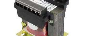
Circuit with transformer
The most common option for lowering the mains voltage to get 12 volts is to use a transformer. For this, a special electrical machine with appropriate parameters for input and output voltage is used.
Stepping down voltage using a transformer
As you can see, a network voltage of 220 Volts is supplied to the high side of the transformer windings. Next, the reduced voltage is alternately supplied in half waves to the input terminals of the diode bridge VD1 - VD4. From the diode bridge, a constant voltage is supplied to the load through filter capacitor C.
This is the simplest version of the circuit with a step-down transformer, but if constant use is necessary, the device can be supplemented with functional elements - a variable resistor or stabilizer.
Advantages and disadvantages of alternating voltage
So why did they choose alternating current rather than direct current for power supply?
When transmitting electricity, current passes through wires hundreds of kilometers long, heating them and dissipating energy into the air. This is inevitable for both direct and alternating currents. But the power loss depends only on the resistance of the wires and the current in them:
The power transmitted along the line is equal to:
It follows that as the voltage increases, less current is needed to transmit the same power, and the power loss decreases. This is why the voltage is increased on long power lines. There are lines for 6kV, 10kV, 35kV, 110kV, 220kV, 330kV, 500kV, 750kV and even 1150kV.
But in the process of transferring electricity from source to consumer, the voltage must be changed repeatedly. It is easier to do this on alternating current using transformers.
The disadvantages of alternating current appear when transmitting energy through cable lines. Cables have capacitance between phases and with respect to ground, and the capacitance conducts alternating current. A leak appears, heating the insulation and causing it to fail over time.
DIY digital voltmeter
> Electrician's tips > DIY digital voltmeter
When working with various electronic products, there is a need to measure the modes or distribution of alternating voltages on individual circuit elements.
Conventional multimeters turned on in AC mode can only record large values of this parameter with a high degree of error.
If you need to take small readings, it is advisable to have an AC millivoltmeter that allows you to take measurements with an accuracy of millivolts.
Consequences of electric shock
Carelessness in handling electrical appliances can, to put it mildly, negatively affect human health. Therefore, you should not experiment with electricity unless you have special skills.
The effect of current on a person depends on several factors:
- resistance of the victim’s body;
- the stress under which the person fell.
- on the current strength at the time a person comes into contact with electricity.
Taking into account all of the above, we can say that the action of alternating current is much more dangerous than direct current. There is experimental data confirming the fact that in order to obtain an equal result in case of injury, the strength of direct current must be four to five times higher than that of alternating current.
The very nature of alternating current negatively affects the functioning of the heart. When an electric shock occurs, an involuntary contraction of the heart ventricles occurs. This may cause it to stop. Contact with exposed veins is especially dangerous for people who have a cardiac stimulator.
Direct current has no frequency. But high voltage and current can also be fatal. It is easier to escape from contact with direct electric current than from contact with alternating current.
This short overview of the nature of electric current and its transformation should be useful to people who are far from electricity. Minimal knowledge in the field of the origin and operation of electricity will help you understand the essence of the operation of ordinary household appliances, which are so necessary for a comfortable and quiet life.
Let's first clarify what we mean by “constant voltage”. As Wikipedia tells us, constant voltage (also known as direct current) is a current whose parameters, properties and direction do not change over time. Direct current flows in only one direction and its frequency is zero.
We looked at the DC oscillogram in the article Oscilloscope. Operating Basics:
As you remember, horizontally on the chart we have time
(X-axis), and vertically
voltage
(Y-axis).
In order to convert a single-phase alternating voltage of one value into a single-phase alternating voltage of a smaller (possibly larger) value, we use a simple single-phase transformer. And in order to convert into a constant pulsating voltage
, we connected the Diode bridge after the transformer. The output received a constant pulsating voltage. But with such tension, as they say, you can’t change the weather.
But how can we get out of the pulsating constant voltage
get the most real constant voltage?
To do this, we need just one radio component: a capacitor.
And this is how it should be connected to the diode bridge:
This circuit uses an important property of a capacitor: charging and discharging. A capacitor with a small capacity charges quickly and discharges quickly. Therefore, in order to get an almost straight line on the oscillogram, we must insert a capacitor of decent capacity.
Dependence of ripple on capacitor capacitance
Let's take a practical look at why we need to install a large capacitor. In the photo below we have three capacitors of different capacities:
Let's look at the first one. We measure its value using our LC meter. Its capacity is 25.5 nanoFarads or 0.025 microFarads.
We connect it to the diode bridge according to the diagram above
And we cling to the oscilloscope:
Let's look at the oscillogram:
As you can see, the pulsations still remain.
Well, let's take a capacitor with a larger capacity.
We get 0.226 microfarads.
We connect it to the diode bridge in the same way as the first capacitor and take readings from it.
And here is the actual oscillogram
Not... almost, but still not the same. The pulsations are still visible.
Let's take our third capacitor. Its capacity is 330 microfarads. Even my LC meter cannot measure it, since my limit on it is 200 microfarads.
We hook it to the diode bridge and take an oscillogram from it.
And here she actually is
Here you go. It's a completely different matter!
So, let's draw some conclusions:
– the larger the capacitance of the capacitor at the output of the circuit, the better. But don’t overuse the capacity! Since in this case our device will be very large, because capacitors of large capacities are usually very large. And the initial charge current will be huge, which can lead to an overload of the supply circuit.
– the lower the resistance load at the output of such a power supply, the greater the ripple amplitude will appear. They fight this with the help of, and also use integrated voltage stabilizers, which produce the purest constant voltage.
How to make alternating current from direct current?
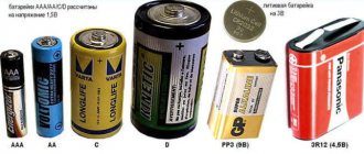
It was said above that all batteries, batteries for flashlights, and TV remote controls have direct current. To convert current, there is a modern device called an inverter; it can easily turn direct current into alternating current. Let's look at how this applies in everyday life.
It happens that while in a car a person urgently needs to print a document on a photocopier. There is a photocopier, the machine works, and by plugging in an inverter adapter into the cigarette lighter, he can connect the photocopier to it and print documents. The converter circuit is quite complex, especially for people who have a vague understanding of how electricity works. Therefore, for safety reasons, it is better not to try to build an inverter yourself.
Methods for generating electricity
Electric current is produced using the following devices:
. They consist of two parts: a stationary stator and a rotor rotating inside it. The stator is a permanent or electric magnet, the rotor contains a winding of wire. When the rotor rotates, the magnetic flux crossing its winding changes all the time, which leads, according to the law of electromagnetic induction, to the appearance of an emf. The rotor is driven by an external force: engine (car), water flow (hydroelectric power plant), steam pressure (nuclear and thermal power plants), wind, etc. The current at the generator output will be variable. To obtain a permanent one, an additional mechanical device is required - a collector;
mechanical generators- galvanic cells (GE) and batteries . Convert chemical energy into electricity through a redox reaction. The simplest GE: copper and zinc plates, immersed, respectively, in solutions of copper sulfate and zinc sulfate, isolated from each other by a porous partition (Jacobi-Daniel element). As a result of oxidation, each zinc atom on the zinc plate (anode) gives up 2 electrons, which pass through the electrical circuit to the copper plate (cathode) and reduce positively charged copper ions on it. GEs are called primary chemical current sources (CHS). Batteries are secondary HIT. The principle of operation is similar, but they first need to impart chemical energy by connecting the system to a current source. The battery can be charged and discharged many times, while the GE is used only once;
- photocells _ The action is based on the ability of semiconductors to generate current when irradiated with light. You can verify this by cutting off the upper part of the transistor body and placing it under the sun's rays: the multimeter will show voltage at the terminals of the device;
- thermoelements . The action is based on the Seebeck effect: in a closed circuit of two wires made of different metals, when one of the two contact zones is heated, an emf occurs between them. Such circuits are called thermocouples and are mainly used as temperature sensors. For example, to measure temperatures from +00C to +1000C, a copper - constantan pair is used, in the range +1000C - +6000C - silver and constantan.
Of all the sources listed, only the mechanical generator provides alternating current. If the current comes from a battery, for example, installed in an uninterruptible power supply (UPS), it is converted from constant to alternating.
Multi-limit instrument
Anyone who has repeatedly encountered transistor designs and circuits knows that very often with a voltmeter it is necessary to measure circuits with voltages from tens of fractions of one volt to hundreds of volts. A simple homemade device with one resistor will not do this, so you will have to connect several elements with different resistances to the circuit. So that you understand what we are talking about, we suggest that you familiarize yourself with the diagram located below:
It shows that there are four resistors installed in the circuit, each of which is responsible for its own measurement range:
- From 0 volts to one.
- From 0 volts to 10V.
- From 0 V to 100 volts.
- From 0 to 1000 V.
The value of each resistor can be calculated based on Ohm's law. The following formula is used here:
R=(Uп/Iи)-Rп, where
- Rп is the resistance of the measuring unit, take, for example. 500 Ohm;
- Up is the maximum voltage of the measured limit;
- Ii is the current strength at which the needle deflects to the end of the scale, in our case - 0.0005 amperes.
For a simple voltmeter from a Chinese ammeter, you can choose the following resistors:
- for the first limit – 1.5 kOhm;
- for the second – 19.5 kOhm;
- for the third – 199.5;
- for the fourth – 1999.5.
But the relative resistance value of this device will be equal to 2 kOhm/V. Of course, the calculated values do not coincide with the standard ones, so resistors will have to be selected close in value. Next, the final adjustment is carried out, during which the device itself is calibrated.
Converter circuits
The simplest solution to the question of how to make 220 V alternating current from direct current does not exist. A diode bridge can do this. The DC/AC converter circuit contains four powerful diodes. A bridge assembled from them creates current movement in one direction. The bridge cuts off the upper bounds of the sinusoid variables. The diodes are assembled in series.
The second circuit of the AC converter is a parallel connection to the output from a bridge assembled from diodes, a capacitor or a filter that will smooth out and correct the dips between the peaks of the sinusoids.
Excellent converts DC to AC inverter. Its scheme is complex. The parts used are not cheap. That is why the price of an inverter is rather high.
Step-by-step instruction
So
,
step one
- an SMD resistor with a resistance of 130 kOhm is removed from the circuit, standing at the input of the positive power wire, between the diode and the trimming resistor 20 kOhm.
Second
. On the freed contact, on the side of the trimmer, a wire of the desired length is soldered (for testing, conveniently 150 mm and preferably red)
Third
. A second wire (for example, blue) is soldered to the track connecting the 12 kOhm resistor and the capacitor from the “ground” side.