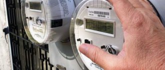
Three-phase electricity meters today are used not only in production, but also in everyday life. They are divided into two types: three-phase electricity meter directly connected and through a transformer. The first option is simplified, and its connection is practically no different from installing and connecting a single-phase meter. These devices are usually designed for a current load of up to 100 amperes, transformer loads of over 100 A, and a throughput power of up to 60 kW.
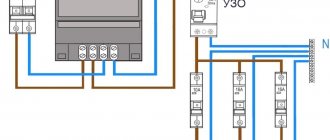
Let us immediately designate the connection diagram. She is in the picture below:
It clearly shows that the input and output phases are located next to each other. Typically, terminals are designated by numbers, so, for example, the input of phase one is terminal number one, and its output is terminal number two. Everything else is also in order.
A three-phase machine must be installed in front of a three-phase electric meter. Replacing it with three single-pole ones is prohibited, because switching of all phases must occur simultaneously.
Installation and connection of a three-phase direct connection meter
Here I will give a practical case when I had the opportunity to change a three-phase meter in one of the organizations in Taganrog.
Organizational aspects of replacing the meter
1. It is necessary to find out why the counter is changing. In my case, there was an order from Energonadzor; this official document is sufficient.
2. At what time do we change. It is important to agree on what time we turn off the electricity and how long it will take. In my case, this is a design firm with a lot of computers and creative people, and inspiration can fly away due to my fault ;). In addition, it is desirable that it be during daylight hours, which is quite logical even if you have a flashlight.
3. How to remove phases for replacement. In the simplest case, like mine, there is a circuit breaker in front of the meter, and removing the voltage is a matter of seconds. But sometimes it is necessary:
- look for the keys to the basement
- look for and negotiate with a local electrician
- find out which group in the RP my consumer is on
- eliminate the moral problems of people who are simultaneously turned off
You can, of course, replace a three-phase meter in the same way as is often done with single-phase ones - work under voltage. But here it is very, very dangerous, even more dangerous than working with one phase at height.
In such cases, I often joke that electricians don’t have to jump from a parachute – there’s already enough adrenaline.
Removing the old meter
Why it had to be changed is not important, but an order was issued which stated that the meter must be of the 1st accuracy class. In addition, the Energomer counter was originally installed, and I decided to install the same one in order to bother less with fasteners during installation. What came of it, read on.
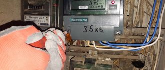
This is what the electrical panel looked like with the old three-phase meter before replacing it:
1 old three-phase meter
At the bottom left you can see the input machine, which made it easy to turn off the power to the meter and easily change it. However, don't relax! The panel contains voltage (380V) at the input (usually upper) terminals of the machine.
If you zoom in on the next photo, you can see that the meter is not that old - 2010. But again, let's not go into that.
2 old counter is closer
Remove the seal and the cover covering the terminals:
3 Remove the cover. We see the terminals
The installation location of the meter after dismantling the old one looks like this:
4 The terminals were unscrewed, the meter was dismantled
Is it possible to install a three-phase device in a single-phase network?
This option has a right to exist. With such switching, the electricity meter will be fully operational. He will simply begin to “think” that there is no current load in the remaining empty phases. However, if the apartment owner makes such a connection, he will face another problem. The energy supply company will not accept a three-phase device connected to a single-phase network and will not seal it. This means that according to all documents, there will be no electricity meter.
Read also: Why do you need a sawmill?
Connecting a three-phase meter instead of a single-phase one is quite possible PHOTO: rabotiagi.com
Energy supply companies explain this by the fact that three-phase devices are not intended for 220 V networks, which means that no one has carried out verification of the accuracy class in such conditions. Consequently, the device does not meet the classification standards and cannot be approved for use. This means that it is not worth installing a three-phase electricity meter in single-phase networks.
Installation of a new meter
It was not possible to buy exactly such a meter, I purchased an Energomera TsE6803V Sh M7 R32. How this name stands – see the instructions, which can be downloaded below.
5 New counter just unpacked
From the back the counter looks like this:
6 New meter, rear view
Connecting a new meter
Not everything went smoothly with the connection, although the old and new meters are from the same manufacturer (Energomer), and at first glance they are similar in design. How the single-phase Energomer meter works is in my other article, Design of a single-phase direct-connection meter. The three-phase one is designed in the same way, someday I’ll publish an article with a photo.
As you can see in the photo below, the counter is mounted on a DIN rail. However, the kit includes a strap for mounting in the shield. I found this out before purchasing, hoping that there would be no problems during installation. But when comparing meters of the same model, it turned out that not everything is so simple for Russian manufacturers.
7 Difference in mounting, the new one is on the left (the meters are on the tiled floor)
The counters are located so that the side holes are at the same level. The goal was to get into the same mounting holes. In this case, the Vertical bar had to be lowered as far as possible, and only then did all three holes coincide. But as a result, the meter terminals dropped by about 2-3 cm.
8 New three-phase meter installed and connected
I had to lower the wires down, lightly pressing them vertically down. The meter connection diagram is given below, but here is what happened in the end:
9 Installation complete
Advantages of connecting to 3 phases
By installing a multi-tariff meter, home or apartment owners receive many benefits:
- savings - some models have day and night charging modes, which allows you to use less energy at night than during the day;
- versatility - devices can be connected to a standard 220 V network or a new 380 V network directly or through a transformer;
- constant monitoring - the meter balances the mains voltage;
- accuracy - accounting of consumed electricity is carried out with an error of 0.2 to 2.5%;
- additional functions - the meters are equipped with an event log, an electric power modem, user recording, and a monitor for data output.
The single-phase version gives an error of up to 5%.
- Types and prices
- general information
- Specifications
- Reviews
Main functions of the meter NP73E.3-9-1:
- measurement and accounting of active and reactive energy (capacitive and inductive) in one or two directions;
- multi-tariff electricity metering (up to six temporary tariffs are available with the ability to set workdays, weekends and special days);
- measurement of active and reactive power, current (instantaneous, average), rms voltage, temperature, frequency, cos f, as well as basic power quality parameters;
- the ability to read daily and 1,5,10,15,30,60-minute profiles with a depth of up to 10,000 records;
- maintaining logs of events and accidents;
- use of an additional low-power relay to disconnect/connect a load of no more than 5A or contactors from the data collection center or according to a schedule;
- remote data reading and meter configuration.
Features of connecting three-phase direct-connection meters
Three-phase direct-connection meters, as a rule, are switched on for a total load of up to 50 kW. But if three-phase consumers are not used (or are used little) - motors, powerful heaters - then you need to make sure that there is no large phase imbalance.
That is, so that the load currents between phases do not differ by more than 20%. In practice, of course, this is difficult to achieve, but we must strive for it. At the design stage, and at the stage of operation and alteration of electrical wiring. There are two reasons.
When one phase is working hard (wires and contacts are heating up, reliability is decreasing), then the other is resting.
The accuracy of the meter readings decreases (this applies to older, inductive models).
When replacing any meter, here's something else you need to remember. It is imperative to check the wiring of the contacts in the electrical panel, especially BEFORE the meter.
For example, in my case, when I pressed the wires down, one of them literally jumped out of the input machine. I was shocked. Apparently, a small current flowed through this phase, since the wire was fine. And if more - heat, smoke, sparks...
In fact, there are more subtleties, but it’s impossible to describe everything, you will install it yourself, you will come across it, write comments.
Principle of operation
Electric meters for three-phase networks differ little from single-phase metering devices. A three-phase electric meter, in fact, is three single-phase ones enclosed in one housing. Two coils are connected to each phase - one current (series), the other volt (parallel). In the alternating magnetic field of the coils there is an aluminum disk connected to a counting mechanism. The more current flows through the windings, the greater the magnetic field and the faster the disk rotates. The windings of each phase have a cumulative effect on the speed of rotation of the disk.
Instructions for a three-phase direct connection meter
Below is the operating manual - in the form of pictures and in the form of a file that can be downloaded free of charge, like everything on SamElectrika.
Operating manual for three-phase direct connection meter_1
Operating manual for three-phase direct connection meter_2
Download the operating manual for the three-phase meter Energomer :
• Operating manual_Energomer / Designation, parameters, connection diagram for a three-phase direct connection meter, pdf, 2 MB, downloaded: 1805 times./
Types of equipment
Depending on the types of measured electrical energy, the following types of three-phase electricity meters are distinguished:
- unidirectional. Active electricity is taken into account according to its modular value, reactive energy is taken into account in quadrant Q1;
- bidirectional. Active electricity is taken into account in two directions (output and consumption), reactive - in quadrants Q1, Q2, Q3, Q4;
- mixed type. Active electricity is taken into account according to its modular value, reactive energy is taken into account in quadrants Q1, Q4.
According to the number of tariffs for measured electricity, they are classified:
- single tariff electricity meters. The installation makes sense if electricity consumption is assessed at a single tariff;
- multi-tariff - they keep track of electricity in 12 seasons for four types of days (working days, Saturdays, Sundays, holidays). Switching between tariffs is carried out using an integrated non-volatile real-time clock. Even when the power is turned off, the watch is maintained by a built-in lithium battery, which lasts for 16 years of continuous operation.
When it is possible to turn off power consumption, the following types of three-phase electricity meters are distinguished:
- without the possibility of disconnecting the consumer from the network;
- possibility of switching off using a relay built into the meter (used in direct switching meters);
- with an external contactor (used in semi-indirect meters).
Three-phase electricity meters can be supplied with or without a backup power input. The first option provides the ability to operate the device via a digital interface and display readings in the absence of phase voltages.
Based on the installation features, a distinction is made between meters mounted on a plane and devices mounted on a DIN rail. Various equipment modifications according to accuracy class are also offered (from 0.2 to 1)
Another photo of the panel with a three-phase meter
I also changed the meter, I’m posting a photo - it’s interesting from an installation point of view.
Installation and connection of a three-phase meter
Installation and connection of a three-phase meter
Vote. Please answer the question:
Typical frequently asked questions from readers
Here is the connection diagram for your installed electricity meter:
Please note that be sure to check all connection diagrams with the passport of the electricity meter installed in your installation. The thing is that these are official materials. If you have installed equipment from another company, there may be some differences, so it’s better to double-check.
Please also note that the electricity metering unit is on the balance sheet of the management company, so you do not have the right to change the connection method or make any adjustments yourself. It is better to contact the electricity supply organization with a corresponding statement about problems found in the operation of the electricity metering unit and a request to accept the appropriate measures. It's their job and they're responsible for it, so don't risk penalties.
How to choose such a device: basic criteria
When choosing an electrical meter, focus on the following criteria:
- Product quality. You should not buy models of metering devices at a low price. The estimated cost of good equipment is no less than 1800-2500 rubles.
- Hull integrity. The electrical appliance must not be damaged; cracks, nicks, and flimsy connections are not allowed.
- Availability of industrial sealing. There must be seals at each outlet of the electric meter. The device cannot be operated without them.
- Specifications. Based on these parameters, the electric meter is selected, taking into account the characteristics and power of the electrical network, as well as the difference in tariffs.
You can use the equipment only after making sure of its quality.
How to connect an electric meter through current transformers?
There are several schemes for such connection. Let's analyze all these schemes in relation to the three-phase connection option. What are electricity meters for? In general, meters are needed in order to take into account the electrical energy consumed in three- and four-wire networks with a current frequency of 50 hertz. Three-phase type meters are of the following types:
- 3*57.7/100 V;
- 3*230/400 V.
Such meters must be connected to a source of electricity using measuring current transformers designed for a secondary current of 5 A and voltage transformers with a secondary voltage of 100 V.
The circuits discussed here are applicable to any type of meters (both induction-type devices and electronic ones).
The first thing to remember when making a connection is that when connecting, it is necessary to observe the polarity of the connection of the windings (L1, L2 - primary; I1, I2 - secondary) of the current transformers. The polarity of the windings of voltage transformers is also subject to mandatory rechecking. The transformers themselves also need to be chosen correctly.
About the principles of connection using current transformers
Let's start looking at connection diagrams with meters that have semi-indirect connection. There are several such schemes.
Ten-wire
In this circuit, the power circuits are separated by current and voltage, which is a significant advantage for reasons of electrical safety.
The negative side of this scheme is that you need a lot of wires to connect.
Now let's look at the purpose of the existing clamps:
- Input wire clamp for phase A;
- Clamp of the input wire of the measuring winding of phase A;
- Output wire clamp for phase A;
- Phase B input wire clamp;
- Clamp of the input wire of the measuring winding of phase B;
- Output wire clamp for phase B;
- Input wire clamp for phase C;
- Clamp of the input wire of the measuring winding phase C;
- Output wire clamp for phase C;
- Input neutral wire clamp;
- Neutral wire clamp.
Current transformer contacts:
- L1 – phase (power) line input contact;
- L2 – phase line output contact (load);
- I1 – measurement winding input contact;
- I2 – measurement winding output contact.
Here is a description of the diagram of such a connection.
Current transformers must be connected to the phase wires with terminals L1 and L2.
Phase A is connected to terminal L1 of current transformer TT1, and terminal 2 of the meter is also connected there. Terminal 1 is connected to pin I1 of CT1.
Contacts I2 of current transformers TT1 and TT2 must be connected together, contacts 6 and 10 of the meter are connected to the same point, after which all this must be connected to the neutral.
Contacts L2 of all CTs are connected to the load. Now let's look at connecting the remaining contacts:
- Contact 3 of the meter is connected to I2 TT1;
- Contact 4 of the counter – I1 TT2;
- Contact 5 of the counter – phase B input and terminal L1 of TT2;
- Contact 7 of the counter – terminal I1 TT3;
- Contact 8 of the counter – phase C input and terminal L1 of TT3;
- Contact 9 of the counter – terminal I2 TT3.
Connecting current transformers in a star configuration
In such a scheme, fewer wires are needed to make the connection. In this circuit, terminals I2 of all current transformers, connected together, are connected to terminal 11 of the meter. Contacts 3, 6, 9 and 10, connected together, are connected to the neutral wire. We connect the remaining terminals in the same way as in the previous version.
Connection diagram using test terminal box
There is a special requirement for connecting electricity meters through transformers (PUE, Chapter 1.5, Section 1.5.23), which means that this connection must be made using a test block (box).
The presence of such a box (block) makes it possible to short-circuit the secondary windings of current transformers, connect a reference (model) meter without disconnecting the load, and change meters by disconnecting all circuits in the test box.
We will ignore only one circuit - a seven-wire circuit (otherwise called a circuit that has combined voltage and current circuits). We do not consider it for the reason that such a scheme is outdated.
Its significant disadvantage is that it has a galvanic type connection between the input and output circuits, and this is a source of considerable danger for those who will service electricity meters.
So we have examined all existing schemes for connecting electric meters using current transformers. Which one to use is an individual matter for everyone. The only thing that needs to be taken into account is the individual characteristics of the location where the device is to be installed and do not forget about the requirements of the special rules of the Electrical Installation Code.
