A three-phase meter is a multifunctional device that reduces energy consumption and is designed to account for electricity consumption. Installing this device allows you to evenly distribute the load on the power supply system. Even minor electrical skills, while observing safety precautions, allow you to carry out independent installation.
Depending on the connection method, devices are of direct and transformer type.
The connection diagram is selected from three types. Direct and semi-indirect are used in residential and domestic buildings, and indirect - in enterprises in high-voltage circuits. A three-phase system is more complex in design than a single-phase system, and larger in size.
General installation rules
Installation is not a difficult operation if you know how to connect the device correctly. Do-it-yourself work is often better than the work of an unreliable craftsman.
When purchasing, it is not so much the date of manufacture that is important as the date of verification of the device. The sealing must be carried out no earlier than a year ago.
Before working with the device, you need to obtain permission and technical specifications (TS) from the energy sales organization. Specifications are the main document against which the device will be checked. Therefore, it is important to study in detail the required technical characteristics of each device and components. This will save you from comments and unnecessary modifications.
Basic concepts:
- An electric meter is a link that passes current with the voltage necessary to power the equipment in the house. Based on the amount of high-power equipment used, a three-phase or single-phase meter is selected.
- Terminals are places for connecting wires. Before starting installation, you should study their markings.
Installation is possible inside each individual apartment or on a common landing, in private houses - inside and outside the building. The location is affected by whether old wiring is being replaced or new wiring is being connected.
The connection diagram for the electric meter is carried out through current transformers or without them. For the indirect type, current and voltage transformers are used.
Electrical safety rules must be observed at all stages. It is important to know that connecting a single-phase electrical appliance to a 380-volt network is not allowed.
Sequence of connection operations
Installation steps:
- turning off the input power;
- removing fillings;
- opening terminals;
- connecting wires.
Before installation, make sure that the network is de-energized using the indicator.
No more than 12 months must pass from the date of sealing. It is allowed to connect a 3-phase meter without visible mechanical damage to the casing and glass of the case.
Installation is possible if the body of the three-phase meter has Quality Control Department seals in the form of a sticker and a government verifier seal.
Operating principle of three-phase meters
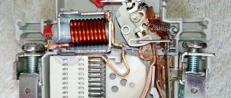
A three-phase electricity meter differs from a single-phase analogue in its ability to function in sufficiently powerful networks . If standard 220V electricity meters are installed in an electrical circuit with a power of no more than 10 kW, then three-phase devices operate with power loads of 15 kW and much more. Such multifunctional devices work equally well both in a standard household network and control the energy consumption of three-phase electric motors. In this case, standard monitoring devices of this type consist of the following structural parts:
- conductive winding;
- voltage windings;
- a worm gear that drives the dial;
- aluminum disk and magnet.
Read also: Requirements for the condition of a turner’s work clothes
Standard induction energy metering devices used in a 380V network, such as “Mercury”, are equipped with plastic cases that protect all mechanisms from moisture or various types of contaminants. Inside the case there are 2 cores around one of which a current winding is wound, connected in parallel to the network. In turn, a voltage winding is wound around another element, the turns of which have an increased diameter compared to the current tax. In the middle between the coils in the formed space, there is an aluminum disk, the rotation of which occurs through the fields created by the windings.
To ensure the display of readings, the meter contains a worm-type mechanism , through which a mechanical pointer or an electronic display is connected to display data. In turn, the magnet is designed to regulate the functioning of the control device. All winding terminals are connected to the terminal contacts of the metering device and output to the phase. To prevent interference in the operation of the electric meter by the consumer, the outputs are sealed by representatives of the electricity supply company.
An important rule for purchasing any type of device for monitoring electrical energy consumption is the mandatory check that the device has all the necessary seals installed at the manufacturer. If such protective elements are not found, then the meter is unsuitable for its intended purpose and its installation has no practical significance.
Installation of the device
Before installing the device, the installation location and type of fastener are determined. The location of the meter in a new house is determined at the building design stage.
Buying a device on a DIN rail is a universal solution, since you can always purchase a convenient mount for the meter.
Installation is possible on a din rail, as shown in the photo:
Instead, you can install a metal plate that comes with the meter. In this case, the device is mounted on a flat surface with three screws.
To turn on the meter, copper wires are used, which are stripped to approximately 2.5 cm. The wires of a three-phase meter are connected all the way into the holes and secured with two screws, starting from the top.
It is important that the insulation does not get into the clamp, just as the bare wire is not allowed to protrude from under the housing.
Before connecting stranded wires to the terminals of a three-phase meter, NShVI lugs are installed on them. For this, special pliers are used. Crimping with lugs guarantees the reliability and safety of contacts and protects against fire in the event of a short circuit.
Connecting wires
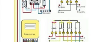
Correct operation is ensured by strict adherence to the connection diagram. Let's look at the example of the Energomer counter.
Input terminals 1, 3, 5 are connected to input phases 1, 2, 3 respectively. Output terminals 2, 4, 6 are connected to output phases 1, 2, 3. The seventh terminal is for zero, the eighth is for output. Grounding is connected to the ground bus.
It is prohibited to connect grounding to the zero phase. Recommendations on how to connect a three-phase meter are indicated on the housing and technical data sheet.
After you have made your own connection, you must call an inspector from the organization supplying electricity. A specialist will assess whether the installation and location of the three-phase meter is correct.
Correct choice of three-phase meter
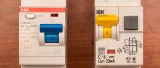
When choosing a three-phase electric meter, it is important to base it on the reliability, accuracy and durability of the device - the main criteria for a high-quality device for metering electricity consumption. In this regard, “Mercury” meters have proven themselves to be excellent, which are produced both with connection via a transformer and directly.
The manufacturer presents a line of both budget devices with an electromechanical electricity control system, and functional meters with an internal tarifficator capable of keeping track of different tariffs simultaneously. Modern Mercury meters are equipped with self-diagnosis and the ability to connect to a personal computer. All devices have electronic seals and have a long service life of up to 16 years. Also, modern Mercury control devices have the following capabilities:
- measurement of active energy type;
- accounting for reactive energy;
- ability to control up to 4 different tariffs;
- the presence of a function that maintains an event log;
- quality control of electrical energy;
- additional interfaces.
Read also: DIY strip bending device
The importance of saving energy is clear to absolutely everyone, and three-phase type meters cope well with the tasks assigned to them. New devices have a function for setting programs and certain operating modes. If during the daytime the tariff is charged at one price, and at night at a different price, then a modern electricity monitoring device keeps records automatically.
Naturally, simply choosing a high-quality three-phase meter is far from enough. Every conscientious owner should understand the various connection schemes for such devices. After all, every person knows that an incorrectly connected electric meter to a three-phase AC network will show incorrect data and there can be no talk of any savings.
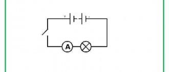
Direct connection
Connecting a three-phase direct connection meter is suitable for low powers and currents not exceeding 100 Amperes. Wire cross-section - from 16 to 25 mm².
The direct connection scheme provides that the supplied wires go directly to the meter, and after that to the circuit breaker.
The photo shows a diagram of a direct or direct connection:
Division of responsibility for electrical appliances
The electrical distribution throughout the facility is protected by separate switches that regulate the maximum permissible current for sections of the circuit. Payment for their purchase and connection is made by the owner of the premises.
The electricity meter and the input machine can be physically located not only in the consumer’s area of responsibility. If these devices are located in a privatized apartment, in a garage, in a utility room or within the boundaries of a cottage or summer cottage, then their installation, maintenance and replacement are carried out by the owner of the property.
According to modern requirements, the panel with the electric meter must be installed outside the dacha or cottage. Therefore, they are now producing models that operate at low temperatures.
His responsibilities also include providing energy service employees and the management company with access to the meter for reading, sealing or checking. Also, specialists have the right to install magnetic seals. If the user of the premises refuses access to the premises without a valid reason, the electricity supplier may transfer him to a general tariff.
If the devices are located in municipal (non-privatized) property, common territory (entrances) or outside a private area, then all costs are borne either by the supplying organization or they are shared. In this case, the organization of work and payment is made by the management company, HOA, GSK or gardening partnership.
We talked in more detail about the legal intricacies of replacing and installing electricity meters in this material.
Semi-indirect method
The direct connection meter is limited in technical characteristics and functions, so sometimes models are selected for installation with current transformers. A diagram of how the meter is connected via current transformers is indicated on the housing and in the technical documentation of the device.
The principle is based on the fact that current circuits are connected through current transformers, voltage circuits are connected directly to a 0.4 kW network. Any switching scheme is considered from left to right.
Installation steps
Installation with transformers is usually chosen for enterprises or domestic premises where powerful electrical equipment is used.
Installation of a meter with current transformers is carried out in the following steps:
- Unscrewing the mounting screws to the required space for inserting wires into the terminal clamp.
- The wire is cleared of the insulating layer to a height of 25 millimeters and inserted into the hole on the meter without distortions (the section of wire with insulation is not allowed to get into the clamp).
- The top screw is tightened first, then the bottom. Lightly tugging the wire downwards ensures that it is securely fixed. After 10 minutes, you need to check the wire again, since copper tends to stretch. If necessary, secure the circuit more securely.
- The remaining wires are connected identically.
- The terminals are covered with a cover.
When the total current load is over 100 Amperes, it is important to connect a three-phase meter through current transformers.
Assembly via transformers
The connection diagram through current transformers can be indirect or semi-indirect.
Connection of current transformers is not applicable for direct connection models. As a rule, the connection diagram is present on the device itself, as well as in the attached instructions.
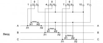
The three-phase electricity meter is connected to transformers in accordance with the markings.
L1 - power supply from the machine (input). L2 - access to the consumer. I1 - input, connected to terminals 1, 3, 5. I2 - output, connected to terminals 2, 4, 6.
For bolt connections, NKI lugs can be used on wires.
Connection example
An automatic device is installed in front of the meter and transformers, protecting against short circuits and blocking the network when maximum loads are exceeded. The three-phase network balances the phase-by-phase load distribution. Each phase is provided with automatic shutdown.
The approach starts from the left side. There are 3 phases on the input circuit breaker: A, B, C. Transformers are conventionally divided into corresponding phases. Wire colors are selected in accordance with GOST. In the diagram, the equipment is marked with colored stickers for clarity.
The diagram involves connecting wires to the terminals of the 3rd phase meter through transformers with their further output to the consumer.
The output wire from the A-input machine is connected to bus L1 of the first transformer. A wire with the same marking is led from I1 of the transformer to the first terminal. From the second terminal the wire is connected to I2 of the first transformer. The seventh terminal in this case is for grounding. The wire from the transformer voltage bolt is routed to the corresponding terminal. In the photos shown, these 3 terminals are in the top row.
A similar transformer connection diagram is applicable for each of them.
Schematic instructions are always indicated on the device itself.
The location of the terminals on Energomer devices is slightly different:
Starting from the left, each three terminals in order constitute one phase. To terminals 1, 4, 7, the circuits are connected from transformer I1. To 3, 6, 9 - from I2. 2, 5, 8 - connection of the voltage circuit. 10 or 11 (Energomera offers 10 and 11 terminals) - neutral conductor (can be either of the two).
Star principle
A similar scheme for connecting a three-phase meter through current transformers makes it possible to use fewer wires. The peculiarity of the “star” is the combination of the I2 terminals of all transformers into a node connected to the neutral conductor.
The disadvantage of this scheme is that it is difficult for services to check.
Three-phase meter diagram
The connection diagram for a direct connection meter, just like for single-phase meters, except for the passport, is indicated on the back of the cover.
- Wires, from left to right:
- first – phase A input;
- second – phase A load;
- third – phase B input;
- fourth – phase B load;
- fifth – phase C input;
- sixth – phase C load;
- seventh – zero input;
- eighth – zero load.
Household use
A three-phase device in a private home is the optimal solution when equipment with high electricity consumption is used. The technology works more efficiently when connected to such a network. Three phases eliminate phase imbalance, which occurs when several devices that require high power are connected to one network at the same time.
For convenience and safety, installation is carried out in special boxes.
Panels with such an accounting system are quite large. Despite the slight difference in voltage with single-phase installations, the three-phase unit ensures uniform distribution throughout the system. This is the main advantage, which allows you to use powerful stoves, heaters, heaters, asynchronous motors, and chainsaws without fear.
Outdoor installation
Installing the system outdoors is possible with effective thermal insulation. At negative air temperatures, correct metering of electricity is not ensured. Usually the actual consumption is exaggerated.
Installation requires special fireproof, sealed boxes. The indicator should be visible through the transparent glass. The electricity meter is connected at a distance of 80-170 centimeters from the ground surface.
Existing electric meter designs
There are several options for this device:
- single-phase or three-phase;
- mechanical (induction) or electronic;
- single-tariff or multi-tariff;
- direct or secondary inclusion.
A two-tariff electricity meter and switching to a night tariff is one way to reduce energy costs.
The use of the expression “two-phase meter” is incorrect. In everyday life, this term refers to single-phase devices with the possibility of tariffication. They are produced by different manufacturers (“Energomera”, “Mercury”, “Neva”, etc.), differ in the number of pins, use cases, accounting capabilities, etc.
When choosing, you need to consider the following:
- Single-phase devices are used where the network voltage is 220 V. For example, when installing a meter in an apartment or office.
- If there are machines or powerful electrical equipment, a 380 V connection is assumed. Three-phase electricity meters are used.
- In both categories, multi-tariff devices are used when the price of electricity differs depending on the time of day or other circumstances.
- Mechanical (induction) devices, unlike electronic ones, cannot be used in unheated rooms. This must be taken into account when installing a meter in a garage and similar structures. However, they are reliable, durable and relatively inexpensive.
- Secondary switching is used where large currents pass - in transformer substations or in the entrance panel of the entrance.
Mechanical metering devices belong to the category of reliable electricity meters.
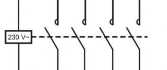
Electricity meters are “modular” devices because, like other switching equipment, they are installed on a special bus - a DIN rail. This is done for ease of installation of electrical equipment in the panel. In addition to the electric meter, there are automatic switches on it.
The machine is connected to the meter to protect the device from voltage surges or a person from electric shock.
Single-phase network
One phase is used in private houses, apartments, and domestic premises. A large number of powerful devices puts a high load on the network. It is optimal to change the network to 3 phases, since one phase may not withstand high voltage, which provokes frequent failures and faster wear of household appliances. If this does not happen, then the following solutions can be applied:
- On some devices (electric stove, water heater) on the back of the housing there are several switching options according to the proposed scheme. A parallel connection is made with the installation of a jumper.
- High-power batteries require a virtual third phase in the form of a capacitor.
In practice, a three-phase electric meter is rarely connected to a single-phase network. The connection is similar to direct, with the difference that the second and third phases are not active. This design may cause problems when testing the measuring device, and in order to obtain permission for installation, additional requirements of the energy supply service must be met.
When deciding to install a three-phase structure in a single-phase network, you need to worry about electrical safety, since in the event of a short circuit the current will be higher. Mandatory inspection of three-phase measuring equipment is carried out at least once a year.
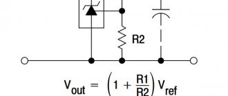
Design and principle of operation of instrument transformers
The classic current transformer for a meter is an inductive converter of a special design, which has two windings with different numbers of turns. Their number in the secondary single-phase coil is usually less than in the primary winding.
Additional Information. The use of a current transformer is one of the ways to reduce the values of operating parameters in order to measure them using conventional instruments.
When current flows in the primary winding of a CT connected in series to the measured line, due to inductive coupling in the second circuit, a load phase current of a smaller magnitude begins to flow. The current coil of a household or industrial three-phase meter, designed to take current readings of electricity consumption, is connected to the same circuit.
Where can I buy
You can purchase devices as quickly as possible at your nearest specialty store. The optimal option, in terms of price-quality ratio, remains purchasing from the AliExpress online store. Mandatory long waits for parcels from China are a thing of the past, because now many goods are in intermediate warehouses in destination countries: for example, when ordering, you can select the “Delivery from the Russian Federation” option:
| Three-phase energy meter DTS238-4-M, LCD display, class 1, 100A | Analogue energy meter for 3 phases | Single Phase Wattmeter and Energy Meter with Timer, Wi-Fi, 65 A |
| Electrical three-phase energy meter RS485, Modbus | Multi-functional 3-phase 4-wire electronic wattmeter, 5-80A | Electricity meter on DIN rail 3 phase 5(100)A 50Hz |