Lecture No. 7. 2. Mutual induction and self-induction
1. Electromagnetic induction. Faraday's law. Lenz's rule.
2. Mutual induction and self-induction. Magnetic field energy.
3. Alternating current. AC operation and power.
4. Capacitive and inductive reactance.
5. The use of alternating current in medical practice, its effect on the body.
1.The current excited by a magnetic field in a closed circuit is called induction current, and the very phenomenon of current excitation through a magnetic field is called electromagnetic induction.
The electromotive force that causes the induction current is called the electromotive force of induction.
In a closed circuit, a current is induced in all cases when there is a change in the flux of magnetic induction through the area limited by the circuit - Faraday's law.
The magnitude of the induced emf is proportional to the rate of change of the magnetic induction flux:
~ (1)
The direction of the induction current is determined by Lenz's rule:
The induced current has such a direction that its own magnetic field compensates for the change in the flux of magnetic induction that causes this current.
=- (2)
[]
2.Mutual induction and self-induction are special cases of electromagnetic induction.
Mutual induction is the excitation of current in a circuit when the current in another circuit changes.
Let us assume that circuit 1 carries current I1. Magnetic flux Ф2 associated with circuit 2 is proportional to the magnetic flux associated with circuit 1.
In turn, the magnetic flux associated with circuit 1 is ~ I1, therefore
(3)
Where M is the mutual induction coefficient. Let us assume that during the time dt the current in circuit 1 changes by the amount d I1. Then, according to formula (3), the magnetic flux associated with circuit (2) will change by the amount , as a result of which a mutual induction emf will appear in this circuit (according to Faraday’s law)
=- (4)
Formula (4) shows that the electromotive force of mutual induction arising in the circuit is proportional to the rate of change of current in the adjacent circuit and depends on the mutual inductance of these circuits.
From formula (3) it follows that
(5)
Those. The mutual inductance of two circuits is equal to the magnetic flux associated with one of the circuits when a current of unity flows in the other circuit. M is measured in Henry[G=Wb/A]
Mutual inductance depends on the shape of the dimensions and relative position of the circuits and on the magnetic permeability of the medium, but does not depend on the current strength in the circuit.
A kennel in which the current changes induces a current not only in other, neighboring circuits, but also in itself: this phenomenon is called self-induction.
The magnetic flux Ф associated with the circuit is proportional to the current I in the circuit, therefore
(6)
Where L is the self-inductance coefficient, or circuit inductance
Let us assume that during the time dt the current in the circuit changes by the amount dI. Then from (6)
,
As a result, a self-inductive emf will appear in this circuit
=- (7)
From (6) it follows that . Those. the inductance of a circuit is equal to the magnetic flux associated with it if a current equal to unity flows in the circuit.
The phenomenon of electromagnetic induction is based on the mutual transformations of the energies of electric current and magnetic field
Let a current be switched on in a certain circuit with inductance L. Increasing from 0 to I, it creates a magnetic flux.
A change in dI by a small value is accompanied by a change in magnetic flux by a small amount
(8)
In this case, the current does the work dA=IdФ, i.e. . Then
(9)
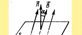
3.A sinusoidal emf occurs in a frame that rotates with angular velocity in a uniform magnetic field of induction B
Since magnetic flux
(10)
where is the angle between the normal to the frame n and the magnetic induction vector B, directly proportional to time t.
According to Faraday's law of electromagnetic induction
=- (11)
Where is the rate of change of the electromagnetic induction flux. Then (12)
Where is the amplitude value of the induced emf.
This EMF creates a sinusoidal alternating current in the circuit with a force
(13)
Where (13)
Where is the maximum current value
R0-ohmic loop resistance
The change in emf and current occurs in the same phases.
The effective strength of an alternating current is equal to the strength of that direct current that has the same power as the given alternating current.
(14)
The effective (effective) voltage value is calculated similarly:
(15)
AC work and power are calculated using the following expressions:
(16)
(17)
4.Capacitance. In a direct current circuit, a capacitor represents an infinitely large resistance: direct current does not pass through the dielectric that separates the capacitor plates. The capacitor does not break the alternating current circuit: by alternately charging and discharging, it ensures the movement of electrical charges, i.e. supports alternating current in the external circuit. That. , for alternating current, the capacitor is a finite resistance called capacitance. Its value is determined by the expression:6
(18)
Where is the circular frequency of alternating current, C is the capacitance of the capacitor
Inductive reactance. It is known from experience that the alternating current strength in a conductor coiled in the form of a coil is significantly less than in a straight conductor of the same length. This means that in addition to ohmic resistance, the conductor also has additional resistance, which depends on the inductance of the conductor and is therefore called inductive reactance. Its physical meaning is the occurrence of self-induction EMF in the coil, which prevents changes in the current in the conductor, and, consequently, reduces the effective current. This is equivalent to the appearance of additional (inductive) resistance. Its value is determined by the expression:
(19)
Where L is the inductance of the coil. Capacitive and inductive reactance are called reactance. Reactive resistance does not consume electricity; it differs significantly from active resistance. The human body has only capacitive properties.
The total resistance of a circuit containing active, inductive and capacitive resistance is equal to
5.The effect of alternating current on the body depends significantly on its frequency. At low, sound and ultrasonic frequencies, alternating current, like direct current, causes an irritating effect on biological tissues. This is due to the displacement of ions in electrolyte solutions, their separation, and changes in their concentration in different parts of the cell and intercellular space. Tissue irritation also depends on the shape of the pulse current, the pulse duration and its amplitude.
Since the specific physiological effect of electric current depends on the shape of the impulses, in medicine it is used to stimulate the nervous system (electrosleep, electronarcosis), the neuromuscular system (cardiostimulators, defibrillators), etc. use currents with different time dependences.
By affecting the heart, the current can cause ventricular fibrillation, which leads to the death of a person. Passing high frequency current through tissue is used in physiotherapeutic procedures called diathermy and local darsonvalization.
High frequency currents are also used for surgical purposes (electrosurgery). They allow you to cauterize, “weld,” tissues (diathermocoagulation) or cut them (diathermotomy)
Mutual induction
Author: Evgeny Zhivoglyadov. Date of publication: March 06, 2015. Category: Articles.
In the article “The Phenomenon of Electromagnetic Induction” a definition of mutual induction was given. It was stated that mutual induction is the influence of a changing magnetic field of one conductor on another conductor, as a result of which an induced electromotive force (EMF) appears in the second conductor. Let us have two conductors I and II (Figure 1) or two coils, or two circuits.
Figure 1. The phenomenon of mutual induction
The current in the first conductor i1 is created by a voltage source (not shown in the drawing). Current i1 forms magnetic flux F1, one part of which F12 crosses the second conductor, and the other part F11 closes in addition to the second conductor:
F1 = F12 + F11.
If instead of conductors we take two coils with the number of turns w1 and w2, then the flux linkage of the second circuit will be:
ψ12 = w2 × Ф12.
Since flux Ф12 is proportional to current i1, the relationship between flux linkage ψ12 and current i1 will be:
ψ12 = M12 × i1,
where
where M12 is a proportionality coefficient called the mutual inductance coefficient or mutual inductance of two coils (or circuits).
The dimension of mutual inductance is determined as follows:
Thus, mutual inductance M is measured in the same units as inductance L.
Mutual inductance depends on the number of turns of the coils, their size, the relative position of the coils and the magnetic permeability of the environment in which the coils are located.
If you pass current i2 through the second conductor, then by analogy you can write:
ψ21 = w1 × Ф21.
And
ψ21 = M21 × i2,
from where we obtain the formula for mutual induction for the second circuit
Using Ohm's law for a magnetic circuit, we can prove that
where Rм is the magnetic resistance of the closed circuit through which magnetic fluxes Ф12 and Ф21 pass.
In expressions
Let's substitute the values ψ12, ψ21, Ф12, Ф21.
Thus, M12 = M21 = M.
Consequently, the mutual inductance of two inductively or magnetically coupled circuits does not depend on which circuit will create the magnetic flux.
When the current i1 changes, the magnetic fluxes Ф11 and Ф12 will change and an induced emf will appear in the second circuit, the value of which will be equal to:
similar:
These emfs are called mutually induced emfs. If the first circuit has resistance r1 and inductance L1, then the voltage U1 applied to this circuit must balance the EMF of self-induction and mutual induction, as well as the voltage drop in the resistance r1 of the circuit:
For the second circuit:
There is a relationship between the inductances L1 and L2 of the circuits and the mutual inductance M:
However, this formula is correct when the entire flow created by the first circuit is coupled with the turns of the second circuit. In practice M is less
, that is
The value k is less than unity and is called the coupling coefficient of the coils. This coefficient would be equal to one if F12 = F1 and F21 = F2.
The electromagnetic connection between two circuits can be changed if the circuits are brought closer together or removed from one another, as well as if the relative positions of the circuits are changed.
In technology, devices are used that operate on the principle of mutual induction and serve to change the inductance of a circuit. Such devices are called variometers. They consist of two coils connected in series, one of which can rotate inside the other.
Let both coils be positioned so that their axes are parallel to one another and the magnetic fields of the coils are directed in the same way (consonant switching). In this case:
where is the system inductance
L' = L1 + L2 + 2 × M.
If you rotate the internal coil 180°, then in this case the magnetic fluxes will be directed towards each other (counter switching).
In this case:
Where
L'' = L1 + L2 – 2 × M.
By rotating the internal coil between the first and second positions, we can change the inductance of the system in the range from L' to L''.
Transformers operate on the principle of mutual inductance and have found very wide application in technology.
It happens that mutual induction is undesirable: two communication lines (telephone) have a mutual influence, interfering with the work of each other. High current lines located parallel to and close to the communication line induce currents in the latter, causing noise and crackling that interfere with telephone conversations.
Figure 2. Mutual induction
And for your development, look at the report of Vladimir Akimovich Atsyukovsky, Doctor of Technical Sciences, on the mutual induction of conductors:
Source: Kuznetsov M.I., “Fundamentals of Electrical Engineering” - 9th edition, revised - Moscow: Higher School, 1964 - 560 p.
Inductance
Inductance is the ability of a coil, circuit or conductor carrying current to accumulate a magnetic field. It characterizes the ability of a conductor to resist electric current. The easiest way to do this is with a coil, because the coil consists of turns, which are circuits. Remember about magnetic flux and a hoop in the rain - a magnetic flux is created in the circuit. Where there is flux, there is electromagnetic induction.
The inductance of a circuit depends on its shape and size, on the magnetic properties of the environment and does not depend on the current strength in the circuit .
Is it possible to increase the inductance of the coil?
Certainly! You can increase the number of turns, for example. Or place an iron core in the center of the coil.
How does a reel work?
A magnetic field is formed around each conductor through which current flows. If you place a conductor in an alternating field, a current will arise in it.
The magnetic fields of each turn of the coil add up. Therefore, a strong magnetic field arises around the coil through which current flows. When the current in the coil changes, the magnetic flux around it will also change.
Problem once
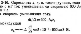
The figure shows a graph of current versus time in an electrical circuit with an inductance of 1 mH. Determine the self-induction EMF module in the time interval from 15 to 20 s. Express your answer in µV.
Solution
Over a period of 15 to 20 s, the current strength changed from 20 to 0 mA. The self-induction EMF module is equal to:
Answer: the self-induction EMF module from 15 to 20 seconds is 4 μV.
Electromagnetic induction
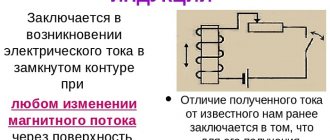
Electromagnetic induction is the phenomenon of the occurrence of current in a closed conducting circuit when the magnetic flux passing through it changes.
The phenomenon of electromagnetic induction was discovered by Michael Faraday through a series of experiments.
Experience once. Two coils were wound on one non-conducting base in such a way that the turns of one coil were located between the turns of the second. The turns of the first coil were closed to a galvanometer, and the second were connected to a current source.
When the key was closed and current flowed through the second coil, a current pulse arose in the first. When the switch was opened, a current pulse was also observed, but the current through the galvanometer flowed in the opposite direction.
Experience two. The first coil was connected to a current source, and the second to a galvanometer. In this case, the second coil moved relative to the first. As the coil approached or moved away, the current was recorded.
Experience three. The coil was connected to a galvanometer, and the magnet was moved relative to the coil.
Here's what these experiments showed:
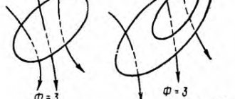
- Induction current occurs only when the lines of magnetic induction change.
- The direction of the current differs when the number of lines increases and when they decrease.
- The strength of the induction current depends on the rate of change of the magnetic flux. In this case, both the field itself can change and the circuit can move in a non-uniform magnetic field.
Why does induced current occur?
Current in a circuit can exist when external forces act on free charges. The work done by these forces to move a single positive charge along a closed loop is equal to electromotive force (EMF).
This means that when the number of magnetic lines through the surface limited by the contour changes, an emf appears in it, which is called the induced emf.
