Installation recommendations
To use the device safely and correctly, the following recommendations must be observed:
- The device must be installed indoors;
- the device must be protected from moisture, as well as from bad climatic conditions;
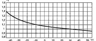
- the required operating environment temperature for the device ranges from -40 to +55 degrees;
- if the upper part of the contact knife burns, it is necessary to clean it with a file;
- It is necessary that the device is securely and firmly installed.
If the changeover switch is installed outdoors, then it is necessary to ensure protection from environmental influences. It is also necessary to ensure that the device operates within the permissible temperature range - that is, if outdoors, then it is necessary to ensure heating of the cabinet where this switch is installed. Installation, maintenance and repair of the device should only be carried out by a specialist, and only when the power supply is completely disconnected.
Finally, we recommend watching a video that explains in more detail how to connect a changeover switch to the network:
It will be useful to read:
- How to install a diesel generator
- How to connect a three-phase voltage stabilizer
- Connecting the generator to the home network
- What is a load switch used for?
A changeover switch is a special device designed to switch electricity to the necessary devices, operating using a manual drive. Manufacturers offer a wide range of such devices, differing in various technical characteristics.
It is important to remember that there are various options for connecting changeover switches - the choice depends on the characteristics of the electrical network. The most popular switch type switches in residential buildings
To change the operating characteristics of such devices, control units are used.
In addition, these devices have found application in industry when operating backup generators. When choosing a changeover switch for a generator, you need to take into account its configuration and the specifics of the existing grounding.
The quality of operation of the device is ensured by equipping it with a grounding electrode. Its marking indicates the degree of protection. It is optimal if it is IP30.
Type of devices
The most common type of changeover products is single-module switches. They are often equipped with copper conductors. It should be borne in mind that such units are best used for generators with operating rates of no more than 20 Hz. However, there are certain disadvantages that should not be neglected when choosing.
It should be noted that during the operation of single-pole products, the maximum load on them can be no more than 200 Amperes. Therefore, it is better to avoid installation in residential areas where a lot of electricity is consumed. In addition, they have a low output voltage of 200 V.
Today, changeover-type devices with two poles are often used. Most often they are installed in residential premises. Switches can operate in both single-phase and two-phase networks. Average negative differential resistance data is 60 ohms.
Output voltage readings may vary. The modification of the product depends on this.
Nowadays, devices of the PP20 series equipped with open capacitors are mainly used. The connection system provides for the presence of a power supply with a voltage of 300 V.
Connection diagram
Change-over switches come in different types: single-pole, double-pole, three-pole and four-pole. The first two versions are used in a single-phase network, the remaining two - in a three-phase network.
These devices are connected to the generator based on the type of electrical network into which the switch will be connected. For a single-phase network, a two-pole device is used, which simultaneously switches the zero and phase of the electrical wiring, eliminating the combination of the generator output voltage and the voltage supplied from the electrical network. A single-pole changeover switch can only be used to switch power between two phases of one electrical network, where the neutral conductor is common and there is no need to switch it with switching devices.
If the generator and the network supplying the house are three-phase, then in this case a four-pole switch is used, which switches three phases and zero between the main network and the backup network from the generator. Three-pole switching devices are used in circuits that supply three-phase loads without a neutral wire. Also, a three-pole device can be used in a single-phase network - in this case, only two poles will be used at the input and output of the switching device.
Installation of changeover switches is carried out in distribution boards, the type of which depends on the design of the switch. There are modular devices that are installed on a standard DIN rail. Plastic shields (boxes) or metal shield housings designed for the required number of modular spaces can be used in the premises.
Outdoors, metal shields are used that have a sufficient degree of housing protection for installation outdoors. Change-over switches of the usual design are mounted in panels supplied with a mounting panel.
A standard DIN rail can also be mounted on the mounting panel of such a shield for installing the necessary modular protective devices.
A cable coming from the metering panel is connected to one input of the changeover switch - this is the main network. A backup network is connected to the second input - a cable from the generator. If the switch has one output, then the cable from the distribution panel is connected to it. Modular versions, as a rule, have two inputs and two outputs, so the two outputs are connected to each other in parallel by jumpers and connected to the distribution panel. Below is a diagram of a single-phase connection of a three-pole changeover switch to the generator and the electrical network:
In order to connect a changeover switch from two three-phase power sources, you need to use the following diagram:
When connecting, it is necessary to observe polarity so that when switching the switch at the output to the home panel, the phase and zero do not change places. The input from the electrical network is protected by a circuit breaker, which is usually installed in the metering panel, and the input from the generator must be protected by a circuit breaker, which is installed in the panel together with the changeover switch.
For industrial enterprises, devices are installed only if the input power is small. And this is how distribution boards are mainly installed - they have a circuit breaker installed at each input. Depending on the scheme, the operation of an automatic transfer switch or manual activation of the reserve by a corresponding automatic machine can be implemented. If changeover switches are used, then, as a rule, only for control without load - the load is removed by automatic switches.
If there is an arc suppression device in the design of the device, the load can be switched using a changeover switch, but in any case, each of the supply lines must be additionally protected by an automatic circuit breaker or fuses, since the changeover switch does not provide protection against emergency operation modes of the electrical network (overload and short circuit).
CS-CS.Net: Laboratory of the Electroshaman
Conventional and reversing switches ABB OT series
Relatively recently, I wrote about ABB switches. Moreover, in ABB itself there are now legends about a certain comrade who bought and broke the OT switch. But that article was not complete - I did not describe the reversing switches and accessories for them there, because at that time I did not have them to take a photo and make a post. But several people asked me questions in the comments and on the phone. And now I’m writing the second part of the post to fill the gap in information =)
Let me remind you of the link to the previous part of the article. There we disassembled two switches (E200 and OT) and saw that the E200, to put it mildly, is a complete mess. And OT switches have contacts that disconnect the line on both sides, all contacts are equivalent and can be used for anything (phase, zero), and their body is extremely durable.
However, it turned out that it was not entirely clear to people what a reversing switch is and how to make it based on the OT switch. And some of the people began to ask: “And I also need to break the zero here - but the 4-pole switches are wildly custom, what should I do?!” So let's figure this out.
And also in 2016, I wrote a post about reversing switches with a motor drive OTM, on which it is very convenient to make an automatic transfer switch because if you insert a handle into this switch, then all the automation is turned off and it turns into a regular reversing switch.
First, let's make a list of items that may be suitable. Firstly, these are the switches themselves. We take the popular 63A ratings because they are guaranteed to fit into any deep panel. Switches with a nominal value of 45, 25A have a smaller height and, if they are placed in the panel, they will be located in its depth.
1SCA105332R1001 ABB OT63F3 Switch up to 63A 3-pole (with handle) 1SCA105365R1001 ABB OT63F4N2 Switch up to 63A 4-pole (with handle)
And reversible:
1SCA105338R1001 ABB OT63F3C Reversing switch up to 63A 3-pole (without handle) 1SCA105369R1001 ABB OT63F4C Reversing switch up to 63A 4-pole (without handle)
So, all reversing switches come without handles. This is done due to the fact that such switches are not necessarily placed in a regular power panel. They can stand in a hellish ASU, somewhere inside a cabinet, and switch inputs or something else. And then you will need different pens. For the shield there is a direct mounting handle. For the ASU cabinet - a special handle for the cabinet door with a long rod.
We will be interested in the most common pens:
1SCA108319R1001 ABB OHBS3/1 Direct mounting control handle (black) for OT16..125F switches 1SCA108688R1001 ABB OHRS3/1 Direct mounting control handle (red) for OT16...125F switches
The reversing switches themselves come in a large box. It is universal, apparently, for several types of switches. It’s also convenient to immediately throw all sorts of accessories into it when you receive the goods from the store. Let's say, immediately throw a pen and something else:
Reversing switches are packed in a large box
...and now let's get straight to the point. Here's the thing. Sometimes we need four-pole switches. They are needed for:
- Disabling not only three phases, but also zero in the three-phase shield at the input. Let's say this is useful with a TT grounding system, when anything can end up on the neutral input wire;
- Switching three-phase input to the generator. In this case, a four-pole switch is required, because the generator and input zeros cannot be combined.
But what a waste! Four-pole switches are not always a warehouse item, and it will be difficult to get them, especially in the regions. And not every store will stock a bunch of positions of different types. And also four-pole reversing switches are a custom item and some stores brazenly steal them from the ABB warehouse for themselves. And such switches last about 8 weeks =)
What to do? Wait? Avotfig! =) It turns out that there is such a mega-cool accessory: an additional power pole ! I will immediately give its nomenclature:
1SCA105461R1001 ABB OTPS80FP Additional power pole for switches OT63…80F3
Let's take a look at all these accessories in a pile:
A bunch of accessories for switches: handles and additional poles
It so happened that I needed to assemble three pieces of four-pole switches: two reversible and one regular. So I bought the usual three-pole ones and a bunch of poles.
First, let's put the handle on. The standard ring is removed from the switch shaft:
To install the handle you need to remove the standard ring
Now we put on the handle (it is put on firmly and tightly) and tighten the screw or hexagon. The type of screw depends on the release date of the pen. Previously they made a hexagon, now they started making a screw.
The handle is put in place and tightened
I remind you! IMPORTANT!!! The reversing switch will NOT FIT into a regular panel like UNIBOX, EUROPA! Haven't tested it on UK500! The switch fits perfectly into AT/U, EUROPA IP65 shields!
Now let's move on to the poles. The pole is an independent thing, which is notable for the fact that (since both contacts open - it doesn’t matter which is movable and which is not) it can be rotated as you like and docked on either side. This means that it can be used for both zero and phase.
Be careful! The poles are different for OT40 switches - they are sold as “left” and “right”! But for switches OT63, OT80, OT100, OT125, the poles do not have such a difference, and the same pole can be placed both on the left and on the right.
(Added in 2022) Many people ask me whether it is worth breaking the zero inside the shields, because they are afraid that the zero pole will break and the zero will burn out right inside the shield. I think like this:
- At the input to the shield, the zero should be broken, because this allows you to turn off the input completely (PE cannot be disconnected!), and also provides a point where it is convenient to connect the input zero (when I figured out the shields on the OT switches, I actually made adapters for the power supply) .
- In the TT grounding system, the zero must be broken MANDATORY, since it does not have re-grounding (this cannot be done in TT - read the post about inputs).
- If we are talking about a switch that breaks zero at the input, then right after this switch we have voltage relays in the panel (all posts about them are under this tag). Therefore, if the zero pole in the switch breaks, then the relays will immediately save us.
- If we need to break the power inside the shield (non-switched lines, non-priority) - then there, if you’re scared, you can only turn off the phases.
But as for the poles of OTPS80FP, I give statistics. As of May 2020 (since 2010), I supplied 182 of these poles. During all this time I came across only one defective pole. Most likely they threw it very hard, and therefore the moving contact inside the pole shifted (the pole did not work as soon as I put it in the shield):
Internals of the additional pole ABB OTPS80FP (threw in the warehouse, the contact moved)
I broke the pole and decided to add to this post.
Here is a photo of the pole contact group:
Additional pole contact group ABB OTPS80FP
To dock the pole to the switch, you need to make two simple movements. First, use hooks to hook it into the grooves in the upper part of the switch:
An additional pole is docked on the side of the switch
Then we turn the switch over and carefully snap the tabs into the other slots of the switch.
First the hooks engage, and then the pole snaps into place
All! In this case we received a 4-pole switch. Moreover, if you order it, it will be EXACTLY the same: a regular one with a docked pole.
Using a pole you can get a 4 or 5 pole switch
And then there is cheating. The same pole can be attached to the other side of the switch. And then the usual three-pole switch will become five-pole. But it is no longer even known where to apply it, because PE cannot be torn.
And now we take two more poles and connect them to our reversing switch on both sides, turning them:
To get a 4-pole reversing switch, we need two poles
And - our switch also became four-pole!
We snap them left and right and get the desired position
Well, now all that remains is to show how to connect such switches (once again).
Firstly, we had an unpleasant situation here, because of which I remind you: THESE SWITCHES DO NOT ACCEPT ORDINARY COMBS!!! DON'T EVER PUT THEM IN THERE!!! If you can’t NOT push two wires into one switch contact, take either a cross-module, or some distribution blocks, or terminals on a DIN rail with a jumper, but don’t push anything here!
There are special things specifically for connecting OT reversing switches:
ABB OZXA38 Connection kit for switches OT63..80F3C (parallel connection) ABB OZXA39 Connection kit for switches OT63..80F4C (parallel connection)
They are mentioned in another post, here: , and to connect reversing switches you should use them, and nothing else. But there is no need to shove ordinary combs into OT switches!
Secondly, the reversing switch consists of two interlocked ordinary ones. ALL their contacts are completely independent! Therefore, the switch can be used:
- Two separate switches. One is completely turned off, the second is completely turned on, or both are completely turned off;
- Switch. The output line is connected to input 1 or input 2, or disabled.
In order to make a switch out of a switch, we need to connect the contacts of the switches in pairs on one side. Here is a photo of the evil shield (there will be a post when they connect it and give me photos). Here you can see that there are two inputs coming to such a switch from above: N, L1, L2, L3 and 1L1, 1L2, 1L3, 1N. At the output of the switch (below), our lines are connected in pairs, and we get 2N, 2L1, 2L2, 2L3.
One of the reversing switches in the panel
And here is the use of the same switch in a single-phase version:
View of connecting the reversing switch
Here you can more clearly see how the connections should be made.
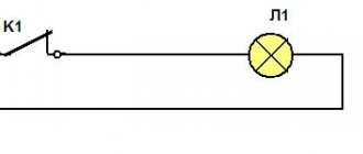
Connection diagram for a pass-through switch from two places
This scheme is convenient in a two-story house on the stairs, in a passage room, in a long corridor. You can also use it in the bedroom - turn off the overhead light at the entrance and near the bed (how many times did you have to get up to turn it on/off?).
Electrical diagram for switching on a pass-through switch from 2 places
Zero and ground (if any) are connected directly to the lamp. The phase is supplied to the output of the first switch, the input of the second is connected to the free wire of the lamp, the outputs of the two devices are connected to each other.
Looking at this diagram, it is easy to understand how the pass-through switch works. In the position shown in the figure, the lamp is on. By pressing the key of any of the devices, we break the chain. In the same way, when in the off position, by moving any of them to another position, we will close the circuit through one of the jumpers and the lamp will light up.
To make it clearer what to connect to what, and how to lay the wires, here are a few images.
Connecting wires on a pass-through switch
If we talk about the room, then you need to lay the wires approximately as in the photo below. According to modern rules, all of them should be located at a distance of 15 cm from the ceiling. They can be placed in mounting boxes or trays; the ends of the wires are inserted into mounting boxes. This is convenient: if necessary, you can replace a broken wire. Also, according to the latest standards, all connections occur only in installation boxes and using contactors. If you make twists, it is better to solder them and wrap them well with electrical tape on top.
The return wire of the lamp is connected to the output of the second switch. White indicates the wires connecting the outputs of both devices.
How to route wires around the room
How to connect everything in the terminal box is described in the video.
3 point circuit
To be able to turn the light on/off from three places, you need to buy a cross (cross) switch for two switches. It differs from those described earlier by the presence of two inputs and two outputs. It switches a couple of contacts at once. See the figure for how everything should be organized. If you understand the above, this one is easy to understand.
Electrical circuit for controlling a lamp from three points
How to assemble such a circuit? Here's the procedure:
- Zero (and ground, if any) is connected directly to the lamp.
- The phase is connected to the input of one of the pass-through switches (with three inputs).
- The input of the second is fed to the free wire of the lamp.
- The two outputs of one three-pin device are connected to the input of a crossover switch (with four inputs).
- The two outputs of the second three-pin device are connected to the second pair of switch contacts with four inputs.
The same diagram, but from a different perspective - where to connect the wires on the housings.
Where to connect the wires
And this is approximately how to distribute it around the room.
Wiring when controlling the lamp from three places
If you need a circuit with four, five or more points, then it differs only in the number of cross switches (for four inputs/outputs). There are always two switches (with three inputs/outputs) in any circuit - at the very beginning and at the very end of the circuit. All other elements are cross devices.
Connection diagram for pass-through switches for 5 points
Remove one “crossbar” and you get a four-point control scheme. Add more and there will be a scheme for 6 control places.
To finally get it all in your head, watch this video.
Pass-through switches always work in pairs
Now take a look at the third option, which shows how pass-through switches should actually be used
Please note that there are two wires between the control points. And this is a big minus for those who hoped to somehow use old veins lying in the thickness of the walls for control.
Look, now you can see that the neutral (black wire) goes straight to the chandelier. But the neutral can be broken or connected at any time from both ends of the corridor. In this case, there is always a phase on one of the wires, and you just need to apply it to the desired point. Due to this, the whole problem is solved.
Now we leave the bedroom, turn on the light, get to the threshold of the kitchen, and turn off the chandelier. By the way, if someone wants to join night gatherings, they will solve their problems in exactly the same manner without any difficulty. But what if we need to place another switch - say - near the front door?
Displaying electrical networks on different diagrams
Changeover switches are displayed on various electrical diagrams, including a single-line diagram, each of which has its own specific features. Knowing these differences will allow you to correctly read and decipher the printed images and accurately identify this or that device. Such schemes can be multi-line or single-line.
The most detailed state of the electrical circuit is displayed in the form of a graphical drawing on multi-line diagrams. Since the transmission of electricity is carried out over a three-phase network, each phase with all connected devices and equipment is recorded on the drawings. Such schemes are called three-line.
In four-line circuits used in low-voltage networks, a neutral conductor PEN or N is added to the phase wires. If there is a protective grounding wire PE, the circuit turns into a five-line circuit.
In accordance with the Electrical Installation Rules, single-phase networks are equipped with a phase, neutral and grounding conductor. These three wires make up a three-line circuit. In the absence of grounding, they often make do with two wires - phase and neutral, assembled in a two-line diagram. The same circuit is used in DC networks, where two wires are used - plus and minus.
In the case of very extensive networks, the use of detailed multiline diagrams becomes not entirely convenient. For this purpose, single-line diagrams are provided, in which a three-phase electrical network is displayed as one common conductor.
What does a pass-through switch look like and work?
If we talk about the front side, the only difference is: a barely noticeable arrow on the up and down key.
What does a single-key pass-through switch look like? You see there are double arrows
If we talk about the electrical circuit, everything is also simple: in ordinary switches there are only two contacts, in pass-through switches (also called changeover contacts) there are three contacts, two of which are common. There are always two or more such devices in the circuit, and they are switched using these common wires.
The difference is in the number of contacts
The operating principle is simple. By changing the position of the key, the input is connected to one of the outputs. That is, these devices have only two working positions:
- input connected to output 1;
- input is connected to output 2.
There are no other intermediate provisions. Thanks to this, everything works. Because the contact switches from one position to another, electricians believe it is more correct to call them “switches.” So a pass-through switch is also this device.
In order not to rely on the presence or absence of arrows on the keys, you need to inspect the contact part. Branded products should have a diagram on them that allows you to understand what type of equipment you have in your hands. It is definitely found on products from Lezard, Legrand, and Viko. They are often absent on Chinese copies.
This is what the changeover switch looks like from the rear
If there is no such diagram, look at the terminals (copper contacts in the holes): there should be three of them. But not always on inexpensive copies the terminal that stands alone is the input. They are often confused. To find where the common contact is located, you need to ring the contacts with each other at different key positions. This must be done, otherwise nothing will work, and the device itself may burn out.
You will need a tester or multimeter. If you have a multimeter, set it to sound mode - it beeps when there is contact. If you have a pointer tester, ring for a short circuit. Place the probe on one of the contacts, find which of the two it rings with (the device beeps or the arrow shows a short circuit - it deviates to the right all the way). Without changing the position of the probes, change the position of the key. If the short circuit is missing, one of these two is common. Now all that remains is to check which one. Without switching the key, move one of the probes to another contact. If there is a short circuit, then the contact from which the probe was not moved is the common one (this is the input).
It may become clearer if you watch a video on how to find the input (common contact) for a pass-through switch.
What is the difference between a pass-through switch and a regular switch?
If you look at the pass-through switch from the side, you will not find any external differences. The significant and only difference between such switches and simple ones lies within their design.
A conventional single-pole single-key switch has two contacts in its design, fixed and movable. The moving contact is driven by a key that we press by hand and closes with the fixed contact. This closes the electrical circuit and supplies power to the lamp. There are also designs of two-pole single-key switches that essentially perform the same function as the previous one. Its difference is that the neutral wire going to the lamp breaks in the same way as the phase wire. This was done to improve security.
Figure 1. Schematic diagram for connecting single-pole and double-pole single-key switches
The pass-through switch has two fixed and one moving contacts. The moving contact is always closed with one of the fixed ones. When you press a key and move it from one position, for example, "off" to another position - "on", the moving contact also changes its position, opening with a closed contact and closing with an open one. That is, the pass-through switch does not have an “off” position and it works not as a switch, but as a switch. Therefore, in technical literature and in manufacturers’ catalogs it is correctly called a switch. For example: “single-pole, single-gang, double-throw switch.” Keep this in mind when you buy switches to assemble a control circuit from two places.
In addition to single-pole switches, there are double-pole and even three-pole switches. For ease of understanding, in this article we will use the expression not a switch, but a pass-through switch, since it is more often used among people.
Connection features
The choice of connection diagram for a changeover switch is influenced by the type of electrical network.
Single-phase network
You can connect such a device to this network only if it has two poles. In addition, you need to take into account that the operation of the switch is only possible if there is a power supply with suitable technical characteristics. As for jumpers that provide contact between two-pole devices, it is advisable to give preference to copper ones.
Two-phase network
How to connect a switch with your own hands if the network is two-phase? The circuit involves the use of a 200V power supply. Also, for these devices you need to use only expansion switches. Only then can the devices be used in a three-phase power supply network, regardless of the number of modules used.
The maximum voltage for such devices will be 300V, and the maximum negative resistance will be 40 Ohms. The contacts in such devices are applicable exclusively to closed models, and fluctuations in electrical energy are controlled using pass-type capacitors.
Three-phase network
For this type of electrical network, reversible switches are used. They provide a complete uninterrupted supply of electric current, distributing the load over several lines and completely preserving the power supply. Here you need to use 400 V power supplies. It would also be appropriate to use pulse transformers.
Types of switches
There are two main types of changeover switches:
Single pole. The most common type. As can be seen in the photo of a single-pole changeover switch, its design is equipped with one module. For this variation, copper conductors are used. This is the optimal choice for generators with a frequency not exceeding 20Hz.
An important nuance is the maximum possible load - 200A. As a result, they are rarely used in residential buildings. Another distinctive feature of single-pole switches is the low output voltage.
Bipolar. The most popular type today. Its area of application is residential buildings. A two-input switch allows you to service devices connected not only to a single-phase, but also to a three-phase power supply. Such devices have a negative resistance of 60 Ohms. Moreover, the output voltage can be very different. It depends on the version of the device used.
Today, most often in stores you can see PP20 switches equipped with open capacitors. When connecting such devices, it is necessary to use 300V power supplies.
Changeover switch principle of operation
An electrical type device that serves to disconnect an electrical load from one energy source and connect it to another source is called a changeover switch, or a changeover type switch (switch with a midpoint). The devices are available with or without arc arresters. In the first case, network switching can occur with a fully connected load. In the second - only when it is turned off.
The switch is operated manually, that is, if it is necessary to switch power sources, the operator acts on the isolated control lever of the switch. There are also automatic switching systems.
Features of using a three-position switch
Three-position changeover switch
A three-pole switch is suitable for connecting backup power to a home line. It is used only after the load has been disconnected. The generator will need to be activated and set to working position. Then you need to connect your home network to it. When carrying out repair work, the switch will be used as a disconnector.
Device installation
Changeover electrical equipment is installed in the switchboard. Models with a plastic case are suitable for indoor installation, and metal ones for external installation. Inside the boxes there is a special DIN rail for switches. Installation of devices is carried out as follows:
- Models that switch off under load are installed vertically.
- The type of tires and wires is selected. Their cross section must correspond to the current rating of the switches.
- Buses and wires are connected to fixed contacts.
- The elements are tightly clamped with terminals to ensure reliable contacts and eliminate the possibility of overheating.
To ensure that the switch works without failures, installation is carried out indoors. The device needs to be protected from moisture, and then checked for tight fit on the DIN rail.
Switching order
Before connecting, you must stop the input machine
Three-position or package devices are produced without a disconnector. They connect like this:
- Stopping the introductory machine.
- Installing the device handle on the generator line.
- Switching off the load breaker.
- Connecting the switch cable to the generator socket.
- Start the generator, wait for warm-up (2 minutes).
- Supplying power to the switch.
- Turning on the load breakers.
Machines are installed on each of the inputs.
How to make a pass-through switch with your own hands - labor lesson
You've probably already looked at electronic catalogs and noticed that a triple pass-through switch can cost a lot of money. What to do? – The eternal Russian question, reinterpreted by Shakespeare as to be or not to be. We would choose the first: definitely not everyone is able to pay that kind of money for pass-through switches. We present to the attention of our readers the first handmade product in RuNet, where it will actually be shown in pictures how to convert an ordinary switch costing around a hundred (this is a really cheap model) into an expensive thing - a pass-through switch. And without any special skills or special techniques.
We look at the first picture and see the switch from which the buttons have been removed
More precisely, it was also taken out of the socket (so to speak), but this is not important now. As you can see from the picture, we have a typical connection diagram for 2 keys
Just in case, the screws of the spacers of the socket box and the clamping contacts of suitable wires are shown and labeled with colored lines. Each and every one of them must be significantly loosened to remove the switch from the wall socket. Do not forget to turn off the power before this, and we also strongly recommend checking with a probe where the phase is located, and somehow draw these places directly along the cambric (plastic insulation of the core). In the future, all this will greatly simplify the process of reinstalling the switch.
Socket spacer screws
Now look at the next picture, which shows the other side of our future victim. In the good sense of the word, of course. Here we see the switch housing clamps that need to be unbent to remove the electrical part. All this is done with a regular screwdriver within a few minutes. Then you need to remove the spring pushers from the plastic frame. The easiest way to do this is with a thick slotted screwdriver. Thin just won't do. You will quickly understand this. There is no need to rush, because this place is the most difficult in the entire process of converting a conventional switch into a walk-through one. In the picture, the spring pushers have already been removed, and moving contacts are visible in the place where they were.
Movable contacts under spring pushers
We skipped the moment of removing the plastic part from the ceramic one (in the pictures), because in our opinion this does not require explanation. At the ends of the entire removed part of the switch there are two weak teeth. Just pry them off with a slotted screwdriver, and let's start converting a regular switch into a walk-through one. Now on the ceramic base of the switch we see groups of contacts:
Three groups of contacts
- General group contact pads.
- Individual contacts for each light bulb.
- Movable rocker contacts.
Now all we have to do is rotate one rocker arm 180 degrees, and cut off one of the contact pads of the general group (it’s better not to isolate it). The resulting position is shown in the last picture. Now the final stage is how it all works. We take and glue both buttons with a Chinese gun so that they become one. Now that one of our contacts is closed, the second one will hang in the air.
Everything ingenious is simple. Therefore, in addition to the fact that we showed how to make a pass-through switch from a regular one, we will add that, in principle, it is not necessary to remove the spring pushers. You can do without this. And you don’t have to glue the two buttons together if you remove the key from a regular switch of the same width and the same manufacturer. Usually the pinout of the legs is exactly the same. All this will allow you not only to make a pass-through switch with your own hands, but also to produce a truly functional and beautiful product.
So, we believe that we have adequately covered the questions asked. They showed how to properly connect a pass-through switch, how not to do this and - most importantly - told how you can save a lot of money in the whole process. We hope that you will like the recommendations, and now every handy owner will be able to boast of having such an original design in his home. Well, what else would you call a pass-through switch?
Photo of the changeover switch
Since the advent of the first Volta battery, switching devices have remained one of the most important elements of any electrical circuit. Simple and complex, powerful and not very powerful, manual and automatic, these devices can be found in almost any electric machine. One of the most important places in a number of switching devices is occupied by changeover switches. Due to their unique properties, these devices are practically indispensable when creating most complex electrical systems.
What is a changeover switch
What an ordinary switch is, perhaps everyone who is more or less familiar with electricity . In essence, this is an ordinary switch, only large and powerful. The handle is in one position - the circuit is closed. In the other it is open. If the switch switches one line, then the device is single-pole, and when you can switch several circuits at once with one handle, then it is multi-pole.
Unlike a conventional switch, a changeover switch has additional contacts, thanks to which the device can not only turn on or off electrical equipment, but also switch. In one position of the handle, the middle bus of the switch is connected to the upper contacts, in the other - to the lower ones.
The most important thing about this design is that the upper and lower busbars cannot be connected under any circumstances. This is what makes the device indispensable when switching equipment that does not allow connections between each other during the switching process. Take a look at the diagram below:
In one position, the lamp is powered by the upper battery according to the circuit, in the other – by the lower one. No matter how hard you try, you will not be able to connect the batteries together. What does this give? Suppose the polarity of the batteries is reversed, and instead of a light bulb you used an electric motor.
In one position of the switch the motor rotates in one direction, in the other - in the opposite direction. But if you accidentally connect the batteries together, then serious problems will begin - a short circuit. In the above example, you only risk draining the batteries, but if you switch more serious circuits - for example, voltages from various power lines - then the slightest mistake by an operator operating conventional switches can lead to a serious accident. A changeover switch, due to its design, will not allow such disgrace, since you simply will not have erroneous options - “either-or”.
The advantages of a changeover switch over a pair of conventional switches are obvious. But what to do if the light bulb in the diagram above just needs to be turned off? Install an additional switch? Not at all necessary, since there are three-position changeover switches. Unlike their two-position counterparts, they have one more position, the so-called intermediate, in which one source from the load is already disconnected, but the second is not yet connected.
Thus, using a three-position switch , you can not only make a switch with one movement of your hand, but also disconnect the load from the source:
Advantages and disadvantages of switches
It remains to consider the advantages and disadvantages of these devices. The advantages include:
- Visibility. The device usually has an open or semi-closed design, which means that its serviceability can be verified visually. Well, since you can clearly see the conductive knives and tires, it will not be difficult to determine in what position the breaker is located.
- Simple design. Almost all such switches, including changeover switches, have an extremely simple design. They are very durable, easy to maintain, and their repair usually does not require high qualifications and is inexpensive.
- High switching power/cost ratio. This is perhaps one of the main advantages of the devices. Some of these devices can switch currents of hundreds of amperes, and are relatively inexpensive.
But switch-type switches also have disadvantages. Here they are:
- Increased danger for the operator. Since most devices have an open design, it is very easy to get energized if handled carelessly. Therefore, only qualified personnel are usually allowed to work with such switches, and the switch itself is often placed in a closed cabinet or housing.
- Irregular switching time. The switching speed of almost any switch depends only on the operator’s reaction. When the knives are slowly moved under load, a high-temperature arc can “stretch” between the opening contacts, which is equally dangerous for both the equipment and the operator himself*.
Arc suppression inserts, which are equipped with some types of switches, help fight the arc only partially. That is why the vast majority of electrical equipment manufacturers recommend switching using switch devices only after removing the load using intermediate circuit breakers.
Rocker switches
These devices have all the properties of changeover switches, but do not have the disadvantages of the latter. Thanks to the special design of the switches, the energy of the operator's hand is not directly used to move the knives, but is accumulated to a certain value, and then makes a quick switching "click". This significantly reduces switching times, reduces the possibility of arcing and allows switching under load. In addition, working with switches is safer, since the devices almost always have a closed design, which means that even an untrained person with zero knowledge of electrical engineering can make switches.
There is an opinion that switches are inferior to switches in power, but this is not entirely true. There are devices capable of switching the same hundreds of amperes, even under load. They are simply quite cumbersome in design and much more complex than conventional switches. Like switches, switches can be three-position and multi-sectional.
Scope of application of circuit breakers and switches
From all of the above, it is clear that such devices are designed to switch circuits that under no circumstances should be connected to each other. One striking example is switching an object to a backup source. Suppose you are tired of constant power outages in your country house and have acquired a gas generator. The electricians turned off the power, you switched to the generator. Turned it on - you are powering your house again from the standard network. Everything is simple in words, but how to do it practically? This is where a changeover switch will help you out. Take a look at the diagram below:
In one position of the switch the house is connected to the network , in the other - to the generator. Moreover, even if there is voltage in both the network and the generator, switching does not threaten anything - it is impossible to connect the network to the generator. Unfortunately, although this scheme is simple, it is not entirely correct. Let's look at the actions you must take when connecting the generator:
- Disconnect the house from the standard electrical network.
- Start the generator and bring it into operating mode.
- Connect the house to the generator.
You don’t need to be a rocket scientist to understand that it is impossible to perform such a sequence of operations with a conventional changeover device. You will either have to start the generator first and then switch, or switch sources and then start the generator.
If the first option is still suitable, then the second is absolutely unacceptable for most household appliances. How will a refrigerator feel, for example, if during the startup of a gas generator the supply voltage begins to rise from 0 to 220 V, and the frequency from 0 to 50 Hz? If you don't know, it will burn.
This is where a three-position device will help you out. We disconnected the house from the network, started the generator, connected the house to the generator. And all with one handle, no additional devices, confusion or extra costs.
DIY changeover switch for a generator
What to do if you don’t have a changeover switching device at your disposal? You can do it yourself. More precisely, not to make, but to assemble from well-known and widespread machines. To do this, it is enough to take two machines and secure them on one bar, having first turned one upside down. In order for both devices to switch simultaneously, you need to install a locking bar (orange in the picture). Especially for this purpose, the sliders of all machines have special holes. The switch is ready. All that remains is to make a connection, which is practically no different from connecting a changeover switch.
Unfortunately, it turned out to be a two-position device, but it has a built-in circuit breaker that will trip in case of overload or short circuit.
Of course, the actual scheme for connecting a generator as a backup source will be somewhat more complicated than those given above - in addition to the switch, you will need certain protection, grounding, and metering devices, but there is nothing complicated here:
Changeover type circuit breaker
All the changeover switches presented above have one drawback - they require the presence of a person to manipulate the switching circuits. This is inconvenient, especially when the central power supply is lost frequently and unpredictably. Therefore, a changeover circuit breaker was developed. More precisely, this is a whole block called automatic transfer of reserve (ATS).
ATS is a complex design, but craftsmen assemble such systems from relatively inexpensive relay devices (contactors). Models with normally closed and open contacts are used for this.
When using a homemade changeover switch, the connection diagram works according to a certain principle. For example, if there is central supply electricity in the line, then a relay with normally open contacts closes the circuit with the load. The relay with normally closed contacts, where the generator is connected, is open in this case. As soon as the current is lost, the combination is reversed and the network begins to power the generator.
Regulatory documents and types of electrical circuits
Electrical diagrams are the most popular when drawing up projects and performing practical work. They are based on numerous variants of the symbolic - graphic designation - UGO, defined by GOST 2.702-2011. This document is known among specialists under the name “ESKD. Rules for executing electrical circuits. It was created on the basis of several norms and rules defined by other types of GOST.
All regulations presented are displayed in the form of clear requirements regarding the details of all types of electrical circuits. The document contains not only a list of symbols relating to devices and products, but also displays the mutual connections between them, as well as the basic principles of operation of each device that uses electricity. Here the rules are defined, according to which you can find out how this or that type of contact connections is designated, features in the marking of conductors, alphabetic and graphic displays of the elements used.
In practical work, electrical engineers use three main types of electrical circuits.
Installation diagram. As a rule, it is displayed in the form of a printed circuit board with an exact indication of the location of parts and elements. Using special signs, their nominal values, principles of connections, fastenings and connections to adjacent components are indicated. Electrical diagrams depicting residential wiring accurately show the installation locations of sockets and switches, lighting and other devices. The lines of cables and conductors are also drawn here, indicating their technical characteristics.
On the schematic diagrams (Fig. 1), detailed designations of all contact connections and other connections, as well as the parameters of elements and networks, are applied. The complete diagram shows the control and monitoring processes of the components and the entire power circuit. The linear diagram displays only the circuit, the details of which are plotted on separate sheets.
Correct connection of a rocker switch to organize three lighting control points
In this case, two single-key pass-through switches are combined with a changeover switch. And this is what it gives. As before, in the picture we used two colors. Imagine that the phase is now in blue. As shown in the picture. Now it's time to go visit. And we turn off the light with one movement of the rocker switch. Isn't that great?
All other options work similarly. Now the light in the corridor can be turned on and off from any of three points. Be it the front door, the kitchen threshold or the exit from the bedroom. Moreover, changeover switches can be arranged in garlands. But they all turn towards each other.
Thus we get the second rule. It applies to both changeover and pass-through switches: the switches are turned on in the opposite direction.
We believe that there is no need to explain these words. They can be clearly seen in the first figure, where the pass-through switches are located sideways to each other. The second one looks outward, that is, towards the power supply and the light bulb in the chandelier.
Where is a similar lighting control system used?
The lighting control system most often considered is used in public and industrial premises, namely: in long corridors, tunnels, walk-through rooms, that is, in rooms where there are two doors equally serving as entrance and exit, in staircases and other places. In all of the above cases, pass-through switches are installed next to the doors.
If we talk about residential premises, then the installation location for pass-through switches can be, for example, the entrance door to the room and a place on the wall next to the bedside table. In this case, a person entering the room will turn on the light by pressing the pass-through switch located next to the door, and sitting on the bed, without getting up, he can turn it off with the second pass-through switch located next to the bed.
Using pass-through switches, you can control one luminaire or lamp, or a group of them. For each case, different types of pass-through switches are used (single-key, two-key, three-key). The main goal that a person pursues when installing such switches is the convenience of light control and reducing energy costs.
Regular switch and pass-through
As can be seen from the figure, the pass-through switch transfers the working contact to one of the output contacts. To make it easier to see, we painted the veins in different colors. In this case, it is clearly visible that at a certain position the neutral and phase are short-circuited. And this is a fire, broken traffic jams, a lot of nerves and worries. Remember a simple rule: a pass-through switch is never placed in the same circuit as a regular one. So that something doesn't work out. There is, however, one working scheme using a changeover switch, which we will consider a little later (you can see the second option in advance in figure number 2).
Figure 2. Operating diagram using a changeover switch
When deciding on three lighting control points in the corridor. It throws the wiring crosswise, due to which interesting possibilities are created for organizing an infinite number of switches
Please note that despite all this manipulation of the neutral and phase, there is no possibility of creating a short circuit. That is, the pass-through switch can be used in conjunction with a conventional
Here's what it might look like in real life:
- The light is turned off, as can be seen from the picture. Because a regular switch broke one of the wires.
- Leaving the bedroom to the kitchen, we turn on the illumination, closing the contact.
- Then we calmly go to the refrigerator (or horizontal bar - whatever).
- Having reached the threshold of the kitchen, we throw the pass-through switch, which simply changes the polarity of the phase and neutral on the light bulb.
Now there are many people who will say that it won’t work like that, but we will answer that if the power was from direct current, and this is often found on ships, cars and trains, then everything would be in order. You just need to put the diode in the right place. As for an ordinary apartment, this combination really doesn’t look the best.
Pros and cons of using switches
The advantage of a changeover switch is its low cost
An electric switch is the simplest device, which is characterized by advantages and disadvantages. The advantages of operation include:
- Visibility. The device can be visually inspected for damage. The position of the knives is clearly visible.
- Simple design. A small number of components simplifies maintenance and repair of the device.
- High switching current. The switch switches current of 500, 630 or 1000 Amps.
- Low cost. You can purchase a switch for installation in a private house or apartment.
Despite the positive characteristics, the machine has several disadvantages:
- Open type design. All elements are in plain sight; if touched carelessly, there is a risk of electric shock.
- Irregular switching speed. If the knives are moved slowly, a high-temperature arc is formed, which burns out the internal components of the device.
- Possibility of short circuit when a high-temperature arc occurs.
- The occurrence of current surges when switching before the load is turned off.
To protect open parts, the changeover relay is hidden in a special box.
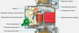
Changeover switch diagram
The changeover switch consists of a housing, blade-type movable contacts mounted on the shaft, stationary contacts, a control handle, an arc chute (if present) and terminals for connecting to the line. The device has two operating positions (contacts 1 and 2) and one neutral (intermediate), in which no load is connected to any of the lines.
A simple connection diagram for two power sources and one load line looks like this: for example, a central power supply is connected to contacts 1, and a diesel or other type of electric generator is connected to contacts 2. The most popular are four-pole and two-pole switches.
The connection of the changeover switch in the case of introducing three-phase voltage into the building is as follows:
- the switch must have four poles;
- four terminals go to the network input;
- four terminals go to the generator input;
- The load is connected to four terminals.
Three of the four terminals go to phases, one to zero.
Switch design
Installation of a reversing circuit breaker in a distribution panel
The reversing circuit breaker has the form of a box with a blade built-in contact system and spring brackets. When closing the first, metal blades enter the brackets. Thanks to this operating principle, contact rupture under its own weight is eliminated. There is a smooth redistribution of electricity from one line to another.
You can fix the switch on the wall in any position - horizontally, vertically and even diagonally. This does not affect its performance.
How to connect a pass-through switch
A. Zemskov has a whole video about this. Not to say that it is ideal, but on the whole it leaves a feeling of complete understanding of the topic within the framework of the material taught by the author. Yes, of course, there were those who made rude remarks like that such things are called switches because they throw the ends of the chains crosswise. But we and our readers understand that all this is out of envy. Everyone wants to see a good renovation in their home, but not everyone can pay for it as much as Project-Service charges. This is where the misunderstanding comes from. As for A. Zemskov himself, in our humble opinion, the little man who managed to earn such a car legally is worthy of all respect. So, today we are talking about how to connect a pass-through switch.
Characteristics
The main characteristics of the changeover switch are:
- The rated current it can carry. The devices are produced at 15.0, 25.0, 32.0, 40.0, 63.0, 80.0, 100.0 and 125.0 A.
- Thermal current that does not destroy elements.
- Permissible mains voltage.
- Short-term impulse voltage that the insulation can withstand.
- The number of poles that a changeover switch can simultaneously switch.
- The wear resistance of electrical contacts is determined by the operating voltage and the amount of current passed.
- The wear resistance of mechanical elements is determined by the number of switching cycles.
Specifications
Characteristic designation structure
All reversing circuit breakers have the following basic technical parameters:
- rated current indicators - from 16 to 3,200 A;
- number of poles – from 1 to 4;
- permissible operating temperature – no more than -40 degrees to +55;
- cable cross-section – from 0.75 to 35 mm2;
- installation type - din rail or mounting plate.
Some models additionally have a control knob.