Leadless design (SMD) resistors, like other components, require markings. From it you can get information about the resistor value and its accuracy. But in the case of SMD components, dimensions become a problem. It is impossible to apply a complete alphanumeric designation in a limited space. Marking in the form of color stripes is also not a solution - there is also not enough space to place the required number of tags. Determining the first familiarity location (where to start reading from) will also become a problem: a thickened line or a marking shifted to one side will also require additional space. Therefore, a special notation system has been adopted for leadless elements.
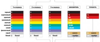
Three-digit resistor numbering with tolerances of 2%, 5% and 10%
If there are three symbols on the body of the device, this means that the resistor has an accuracy of 2% to 10%. There are two options for three-digit marking of electronic components - completely digital and alphanumeric designation.
Three digits
In most cases, the marking consists of three digits XYZ. They represent resistance in the form XY⋅10Z. An example of such a designation is 332. The first two digits mean 33 Ohms, and the third is the power to which the number 10 must be raised and then multiplied by 33. Simply this means the number of zeros that must be added to the right of the first two numbers. In this case, the marking means 3300 Ohm = 3.3 kOhm. If the third digit is zero, then there is no need to add anything (10=1). So, marking 100 means 10 Ohms (10×1). There are no decimal factors less than one (0.1 or 0.01) in this system.
Transistors in KT-26 type housing
To designate the group, the following color markings of transistors are used: group A corresponds to a dark red dot, B - yellow, C - dark green, G - blue, D - blue, E - white, G - dark brown, I - silver, K – orange, L – light tobacco, M – gray.
The type is indicated by the symbols and colors shown below.
- KT203 corresponds to a right triangle (sides down and to the right) or a dark red dot.
- KT208 – small circle (there is no color marking for this type).
- K209 – rhombus (gray dot).
- K313 is a symbol that resembles an inverted letter T (orange dot).
- KT326 – inverted equilateral triangle (brown dot).
- KT339 – equilateral triangle (blue dot).
- KT342 – quarter circle (blue dot).
- KT502 – half a circle (yellow dot); KT503 – circle (white dot).
- KT3102 – right triangle with legs up and to the left (dark green dot).
- KT3157 – right triangle with legs to the left and down (no color designation).
- K366 – letter T (no color).
- KT6127 – inverted letter P.
- KT632 – no symbol (silver dot).
- KT638 – without symbol (orange dot).
- KT680 – letter G.
- KT681 – vertical stick.
- KT698 – letter P.
Marking of SMD resistors according to EIA-96
The four-digit designation of resistor parameters is not the optimal method. Still, there is not enough space for four characters on small-sized cases. Therefore, for devices with an accuracy of 1% for form factors below 0805, a different marking system is used, consisting of two numbers and an alphabetic symbol. This designation is introduced by the EIA -96 , according to which two numbers indicate the nominal value in ohms, and the letter indicates the multiplier.
Table of codes and resistor marking values
In the EIA-96 standard, there is no direct correspondence between the marking numbers and the denomination. The actual resistance value is associated with a code. To determine the resistance value, you need to refer to the table:
Table 1. Table of codes and resistor marking values according to EIA-96.
So, code 20 corresponds to a value of 158 Ohms, and code 69 - 511. Obviously, it is very difficult to remember the correspondence between the code and the nominal value. Therefore, it is recommended to use a table or an online calculator.
Multiplier table
The multiplier table is smaller, but also non-obvious and difficult to remember:
home
Marking of SMD Components
The huge variety of SMD element markings creates great difficulties for the correct identification and purpose of the SMD component, as well as technical characteristics, and the ability to select an analogue.
The table posted on the website partially solves this problem; SMD components - semiconductors (transistors, diodes, zener diodes and some other elements) are placed in alphabetical - digital order, which simplifies the search. To do this, just type the first character of the marking or use the site search by typing the full code in the search bar.
Modern radio editing
With the advent of microelectronics, the requirements for the installation of electronic components have changed significantly, and the requirements for tools have changed accordingly. If in the 80s - 90s almost any installation was carried out only with the help of a soldering iron, modern installation requires the presence of completely different technological equipment: convection ovens, industrial hair dryers, high-precision soldering stations, where the temperature at the end of the tip can be maintained with an accuracy of a degree. The requirements for the materials used have also changed: solder, flux, all kinds of active and passive additives (pastes), without which it is impossible to obtain high-quality soldering.
Although modern elements are much higher quality than their counterparts from the 90s, they nevertheless require certain skills when handling them, especially for SMD elements; one awkward move can result in many hours of cleaning a board or microcircuit. The site will give some tips on mounting SMDs. Also in the left column of the site there is data on chip resistors and chip capacitors.
To help the masters. Tables
High-quality repair of equipment largely depends on the correct identification of a failed element or group of elements, determination of the nominal value, type, technical specifications. characteristics. That's why ,
You should always have on hand reference literature, all kinds of manuals, tables of color coding of resistors, capacitors, inductances, as well as other elements necessary for repairs. Availability of reference information will ensure fast and high-quality repair of electronic equipment. This is especially important: if the repair is carried out at the client’s location, at the permanent location of the electronic device. To make your search easier, there are sites with graphic marking tables that will provide you with information about any common element in a matter of seconds. You can access such a site from any modern mobile phone.
Examples of decoding alphanumeric markings of SMD resistors
To determine the resistor parameter, it is not necessary to memorize tables of values. There are many online calculators on the Internet, and many offline programs are also available for download. But if you understand the principles of marking, it is possible to determine the values of resistance and accuracy without resorting to reference books; after a little training, this is obtained at first glance. To consolidate your understanding of the basics, you need to look at several practical examples.
Resistors 101, 102, 103, 104
In all these examples, the numerical value of the resistance is the same, equal to 10, but the multipliers in each case are different:
- 101 - 10 Ohms must be multiplied by 101, that is, by 10, or added to the value of one 0 - the total will be 100 Ohms;
- 102 - 10 Ohms must be multiplied by 102, that is, by 100, or two zeros must be added to the value - you get 1000 Ohms (= 1 kOhm);
- 103 - 10 Ohms must be multiplied by 103, that is, by 1000, or three zeros must be added to the value - you get 10,000 Ohms (= 10 kOhms);
- 104 - 10 Ohms must be multiplied by 104, that is, by 10,000, or four zeros must be added to the value - you get 100,000 Ohms (= 100 kOhms).
It is easy to remember that for a three-character encoding, the last digit 3 indicates kilo-ohms, and 6 - mega-ohms - this will further facilitate visual reading of the marking.
Resistors 1001, 1002, 2001
If there are 4 digits on the body of an electronic component, this means that its accuracy is at least 1%. And the denomination also consists of a mantissa and a multiplier, which is specified by the last symbol:
- 1001 - 100 Ohms must be multiplied by 101, that is, by 10, which is equivalent to adding one zero to the mantissa - the result will be 1000 Ohms (1 kOhm);
- 1002 – the mantissa is also equal to 100 Ohm, but the multiplier is equal to 102=100 (two zeros must be added), and the nominal value will be equal to 10000 Ohm=10 kOhm;
- 2001 - in this case, 200 Ohms must be multiplied by 101 = 10, the nominal value is 2000 Ohms = 2 kOhms.
What are the labeling standards?
The markings that are applied to the body of SMD elements, as a rule, differ from their brand names. The reason is trivial - lack of space due to the miniature size of the case. The problem is especially relevant for electronic electronic devices, which are placed in packages with six or fewer leads.
These are miniature diodes, transistors, voltage stabilizers, amplifiers, etc. To figure out “what is what”, a real examination is required, because it is very difficult to identify the type of ERE using one marking code without additional information. More than 20 years have passed since the appearance of the first SMD devices.
Despite all attempts at standardization, manufacturing companies are still stubbornly inventing new types of SMD cases and haphazardly assigning marking codes to their elements.
Material on the topic: ringing a transistor with your own hands.
It’s not so bad that the applied symbols do not even closely resemble the name of the ERE; the worst thing is that there are cases of “plagiarism” when the same codes are assigned to functionally different devices from different companies.
| Type | Name of ERE | Foreign name |
| A1 | N-channel field effect transistor | Feld-Effect Transistor (FET), N-Channel |
| A2 | Double-gate N-channel field-effect transistor | Tetrode, Dual-Gate |
| A3 | Set of N-channel field effect transistors | Double MOSFET Transistor Array |
| B1 | Field-effect P-channel transistor | MOS, GaAs FET, P-Channel |
| D1 | One diode for wide application | General Purpose, Switching, PIN-Diode |
| D2 | Two widely used diodes | Dual Diodes |
| D3 | Three widely used diodes | Triple Diodes |
| D4 | Four widely used diodes | Bridge, Quad Diodes |
| E1 | One pulse diode | Rectifier Diode |
| E2 | Two pulse diodes | Dual |
| E3 | Three pulse diodes | Triple |
| E4 | Four pulse diodes | Quad |
| F1 | One Schottky diode | AF-, RF-Schottky Diode, Schottky Detector Diode |
| F2 | Two Schottky diodes | Dual |
| F3 | Three Schottky diodes | Triple |
| F4 | Four Schottky diodes | Quad |
| K1 | “Digital” NPN transistor | Digital Transistor NPN |
| K2 | A set of “digital” NPN transistors | Double Digital NPN Transistor Array |
| L1 | “Digital” PNP transistor | Digital Transistor PNP |
| L2 | A set of “digital” PNP transistors | Double Digital PNP Transistor Array |
| L3 | Set of “digital” transistors | PNP, NPN | Double Digital PNP-NPN Transistor Array |
| N1 | Bipolar LF transistor NPN (f < 400 MHz) | AF-Transistor NPN |
| N2 | Bipolar RF transistor NPN (f > 400 MHz) | RF Transistor NPN |
| N3 | High voltage NPN transistor (U > 150 V) | High-Voltage Transistor NPN |
| N4 | “Superbeta” NPN transistor (r“21e > 1000) | Darlington Transistor NPN |
| N5 | NPN transistor set | Double Transistor Array NPN |
| N6 | Low noise NPN transistor | Low-Noise Transistor NPN |
| 01 | Operational amplifier | Single Operational Amplifier |
| 02 | Comparator | Single Differential Comparator |
| P1 | Bipolar LF transistor PNP (f < 400 MHz) | AF-Transistor PNP |
| P2 | RF bipolar transistor PNP (f > 400 MHz) | RF Transistor PNP |
| P3 | High voltage PNP transistor (U > 150 V) | High-Voltage Transisnor PNP |
| P4 | “Superbeta” PNP transistor (p21e > 1000) | Darlington Transistor PNP |
| P5 | PNP Transistor Set | Double Transistor Array PNP |
| P6 | Set of transistors PNP, NPN | Double Transistor Array PNP-NPN |
| S1 | One suppressor | Transient Voltage Suppressor (TVS) |
| S2 | Two suppressors | Dual |
| T1 | Reference voltage source | “Bandgap”, 3-Terminal Voltage Reference |
| T2 | Voltage regulator | Voltage Regulator |
| T3 | Voltage detector | Voltage Detector |
| U1 | FET amplifier | GaAs Microwave Monolithic Integrated Circuit (MMIC) |
| U2 | Bipolar amplifier NPN | Si-MMIC NPN, Amplifier |
| U3 | Bipolar amplifier PNP | Si-MMIC PNP, Amplifier |
| V1 | One varicap (varactor) | Tuning Diode, Varactor |
| V2 | Two varicaps (varactors) | Dual |
| Z1 | One zener diode | Zener Diode |
It will be interesting➡ How do stabilizers differ from zener diodes?