How to make a surge protector with your own hands Schemes for assembling a surge protector at home.
Find out how you can make a surge protector from scrap materials Reading time: 21 min Category: Audio
- Simple surge protector device
- Schematic diagram
- Industrial and homemade filters for a three-wire power system
- How to make it yourself
- Homemade power filter
- Selection and acquisition of equipment
- Making your own surge protector
- 2 simple circuits to repeat with your own hands on a two-wire network
- Details
- Model range of Pilot network filters
- Basic performance characteristics of filters that are important to know
- Self-production
- Choosing between industrial and homemade options
Simple surge protector device
There are two types of SF:
Built-in
Compact SF boards are part of the internal structure of various electronic equipment. They are equipped with computers and other complex equipment.
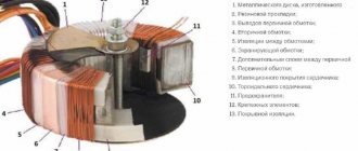
The photo shows the SF device. The following parts are installed on the board:
A varistor is a resistor with variable resistance. If the standard voltage threshold (280 V) is exceeded, its resistance can decrease tens of times. The varistor performs the function of surge protection.
Stationary – multi-channel
The device body has several sockets. Thanks to this, it is possible to connect all existing electrical equipment in one room to one outlet through a filter. To remove high-frequency radio interference, a simple LC filter is used. Fireproof thermal fuses prevent power surges. Some models use disposable fuses.
Uninterruptible power supply (UPS)
In a specialized store, sellers may vie with each other to offer a stabilizer, a surge protector and a UPS. What is better to buy is difficult to decide right away given the existing large selection of models with different names and properties.
Many people purchase a UPS to eliminate one possible fault in the network - a sudden loss of voltage, in order to correctly shut down the operation of electronic devices. Imported models are designated UPS. It is advisable to purchase them with a stabilizer function to eliminate radio frequency and electromagnetic distortion and interference.
If the supply voltage disappears or decreases beyond the required range, the UPS switches to working through batteries. Depending on the model used, the operating time of an independent source can reach several minutes or hours. The device is selected according to the power of the equipment being protected.
An important characteristic of a UPS when operating on battery power is the output voltage shape. For cheap devices it is rectangular, and in frequency and amplitude it is equal to the mains sinusoidal voltage
Schematic diagram
Figure 2 shows a typical power supply network filter circuit. It shows a three-wire (European) power supply network: “phase” - “zero” (“neutral”) - “ground”. Immediately at the filter input there is a varistor VR1.
Its task is to suppress high-voltage surges in the network. When such a surge appears, the electrical resistance of the varistor drops sharply, and it closes this interference through itself, not allowing it to pass further. Next, inductor T1 and capacitors C1, C2, C3 are included, forming an LC filter.
The resistance of the inductor increases with increasing frequency of the current, and the resistance of the capacitors decreases, so that all high-frequency noise is delayed or “drains” into the ground.
Interference can occur not only between the network wires (“phase” and “neutral”), they will be filtered by capacitor C3, but also between the “phase” and “ground”, and interference “neutral” - “ground” is also possible. To effectively suppress such interference, capacitors C1 and C2 are used.
Rice. 2. Typical power supply network filter circuit.
In the absence of ground, the common point of capacitors C1 and C2 “hangs” in the air, which leads to the creation by them and inductor T1 of a parasitic oscillatory circuit, which begins to emit a high-frequency electromagnetic field, becoming a source of potential danger for nearby radio equipment.
Rice. 3. Network filter circuit without grounded capacitors and connection to ground.
Therefore, in a two-wire network, filters are used without these capacitors and connection to the ground (Fig. 3). A typical amplitude-frequency response (AFC) of a network filter is shown in Fig. 4. From this graph it is clear that the higher the frequency of interference, the more effectively it is suppressed.
Rice. 4. Dependency graph.
It is worth dwelling on one feature of power filters. It will all be about the same “land”. There is a whole class of network filters in which the grounding wire has no connection with the internal circuit, except for the corresponding contacts of the Euro sockets themselves and the grounding contact of the Euro plug.
This achieves an important advantage: when operating from a grounded network, all filter sockets are grounded, as expected. But if there is no “ground” in the power outlet (a typical case of a domestic power supply network), all filter outlets are connected to each other via a grounding contact (of course, the filter itself is not grounded)
Why is it important?
Let's imagine, for example, a diagram of connecting various peripherals to a computer, shown in Fig. 5a (typical case - a printer, scanner, external audio amplifier, etc. are connected).
This is an ideal scheme: everything is connected to a grounded power supply network, the potentials of the device housings are the same (zero), since they are connected to ground. In the event of a breakdown or damage to the insulation of any of the devices, the “excess” voltage will go into the ground.
Rice. 5. Schemes for connecting various peripherals to a computer.
Now let's take a connection diagram for the case of a network without grounding (Fig. 5b). As you can see, there is no ground wire, and the only connection between the device cases is a low-current interface cable (more precisely, its braided shielding).
If there is a difference in potential between the computer case and the external device (and this happens all the time!), equalizing currents flowing from a higher potential to a lower one can easily “burn out” the input and output ports of the connected devices.
There are many such cases. The most common is the burnout of the input or output of the sound card if it is connected to an external signal source or to a sound amplifier.
To solve the problem, you need to connect these devices to a “European” extension cord, not even connected (for lack of it) to an external “ground” (Fig. 5c). Here, the electrical potentials of all devices are equalized, through currents will choose an easier path through the grounding contacts of Euro sockets, and nothing bad will happen.
Scheme of SF protection against network interference
A typical network filter circuit is the basis of all devices of this type, with the exception of additional details. The classic is connecting to the points: Ground, Phase and Zero. A varistor VDR 1 is installed at the input. It suppresses voltage surges in the mains current. With a high voltage surge, the resistance of the varistor drops sharply, thereby preventing the interference from passing further through the circuit.
To dampen small voltage changes, inductor Tr1 and three capacitors C are used. Capacitors C1, C2 and C3 are reactive radio components that constantly change the resistance level. It increases sharply when the current frequency changes.
Normal current passes through the filter unimpeded. At the same time, high-frequency interference is delayed in the SF. The filter resistance is directly proportional to the current frequency. Both indicators increase simultaneously, which makes it possible to delay interference on the way to the consumer.
Note! A three-wire power supply network may be subject to interference in the phase-zero, ground-phase, and ground-zero sections. Effective suppression of such negative phenomena is carried out by normal standard grounding of the SF.
Industrial and homemade filters for a three-wire power system
Among the mass-produced products there are quite useful technical solutions that the home craftsman should pay attention to
Brief overview of useful functions of factory models
One of the popular developments, widely represented in the trade, is the Pilot series of filters of different designs.
The circuit diagram of the Pilot surge protector is shown in the picture to make it easier to understand its capabilities.
I will dwell on the tasks that Pilot XPro, specially created for comfortable work, extending the life of connected consumers and reducing electricity consumption, is designed to solve. This:
- protection against surge voltages by varistors;
- prevention of high-frequency interference by inductive-capacitive reactances;
- power management through the introduction of the Master Control function;
- protection against overvoltage associated with zero loss;
- smooth switching off and switching on of equipment under load with the Zero Start function due to the elimination of current surges by the built-in circuit;
- automatic switching on of consumers after elimination of emergency power failure;
- two levels of protection against current overloads or short circuits due to a fuse and a bimetallic release;
- indication of network connection and supply voltage level;
- temperature control and automatic shutdown when overheating.
The Master Control function defines one socket as the main socket (as a master socket). The main consumer with a power of more than 50 watts is connected to it, for example, a computer system unit.
When it is turned on, the automation simultaneously powers three other sockets with peripheral equipment. It also turns them off when power is removed from the main unit.
There are sockets on the case that are not controlled by microprocessor automation. They are used for lighting, telephones, and other equipment.
You can find out more detailed information about this equipment in a short video by the owner of ZIS Company.
How to choose and buy a filter
All of the information listed above should help you decide on the type of device directly in the store.
However, pay attention to two more questions:
- total power consumption of the connected load;
- the presence of sockets in the housing that do not provide voltage filtering, but work as a simple extension cord (such a device is also found).
For the device shown in the photo, the maximum permissible load is marked on the back of the case and is limited to 10 amperes.
For normal operation, we recommend having a reserve of about 30 percent minimum, that is, loading this model with no more than 7 amperes. This is quite enough for complex household appliances with electronics. After all, there is no need to power electric boilers, heaters, incandescent lamps and electric motors through a surge protector. They operate normally on voltage with high frequency noise.
We also recommend watching the CompsMaster owner’s video “Choosing a surge protector.”
Now it’s convenient for you to ask questions on the topic and share this material with friends on social networks.
Useful products
- Disappearing ink pen
- Sleeping bag
- Electric shaft with remote control for roller blinds
How to make it yourself
The easiest way to make a passive low-pass filter. This is due to the fact that it is manufactured using only a few elements. Among the features of doing the work yourself, we note the following:
- Detailed calculations are carried out. You can increase convenience by using special calculators, which are used to calculate the parameters of the main elements of the product.
- The most suitable scheme is selected. It involves the use of a special separator, which is made in the form of an adder. In this case, high-quality sound cannot be achieved, but the device will last a long time.
A simple filter for a 2-way amplifier is easy to assemble. The instructions for carrying out the work are as follows:
- A signal is sent to the input of the operational amplifier.
- A signal is sent to MS2.
- The signal from the low-pass filter output is transferred to MS2.
- The voltage stabilization unit is created on the basis of a resistor, capacitor and stabilizer.
- When the supply voltage is less than 15V, resistor R11 is excluded from the circuit. The input signal adder is assembled on components R1, R2, C1, C2. This item is disabled when a mono signal is input. The signal source is connected directly to the second contact.
- Capacitor C7 is designed to filter the output signal. The signal controller is based on R9, R10, C8.
- To obtain the device you will need a printed circuit board. You can make it yourself from fiberglass, the recommended sheet dimensions are 2 by 4 cm.
- The surface is polished to a shine and then degreased. The printed drawing of the circuit is transferred to the surface.
- Etching is carried out using a special composition. Excess copper is dissolved, after which the surface is washed with clean water.
To connect individual elements, soldering is carried out. If the circuit is assembled correctly, it should work immediately, with no additional configuration required. If there is no sound, you will have to check the reliability of all connections. During operation there is a possibility of damage to the main elements.
Active filter
The active subwoofer filter has become very widespread. Such a scheme has the following features:
- The active element does not load the speaker system.
- The input signal is filtered. Due to this, it is possible to eliminate noise.
- With the right approach, you can flexibly configure the amplifier.
- The original spectrum is often divided into several channels. The active filter circuit allows you to select low, mid, and high frequencies.
You can make an active filter yourself; this does not require special equipment.
Passive filter
A passive device is easier to manufacture, but has less attractive characteristics. Its features are as follows:
- Designed to filter out low frequencies in a given range.
- Doesn't boost the signal.
There are a large number of passive filters on sale. They can last for a long period and are relatively small in size.
How to choose?
The best option, which combines the properties of a surge protector and a stabilizer in one device, is a UPS with a battery, which is an uninterruptible power supply. The UPS is characterized by a smooth sinusoidal voltage drop, so it is used to stabilize the operation of household appliances and computers. The choice of a surge protector for home or professional use is made after studying all the features and characteristics of the electrical network. Many modern buildings have grounding, but there are old buildings that do not have such protection; for such cases, a reliable surge protector is required. Often in one apartment different filters are used for the TV, for the refrigerator, for home equipment.
When choosing a surge protector, you need the following.
- Determine the power of the device - calculate how many devices and with what power will be simultaneously connected to the filter, add a margin of at least 20% to the total number.
- The parameter of the maximum energy of the input pulse is important - the higher this indicator, the more reliable the network device will be.
- Determine whether there is a thermal fuse in the filter that protects the filter from overheating.
- Determine the number of sockets to connect, and if devices need to be frequently disconnected from the network, then it is better to choose a filter with autonomous shutdown of each socket.
- Consider what length of electrical cable will be needed.
Homemade power filter
I bring to your attention two very simple but reliable methods on how to make your own power filter for a car radio. The main advantage of the presented homemade devices is their price and ease of manufacture, which in no way relieves you of personal responsibility for the possible consequences of connecting homemade power filters.
Method one
This circuit consists of four capacitors and a coil:
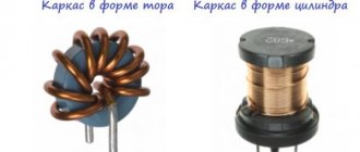
Make your own filter for car radio
- The capacitances of the capacitors are taken at 4700 and 1000 μF (be sure to shunt them by 0.1 μF);
- A coil with an inductance of 100 microhenry has a winding on a ferrite ring made of enamel wire with a cross-section of 0.9.
Filter for car radios
The advantage of this circuit is that each element in it plays the role of a kind of filter: electrolytic capacitors smooth out various interferences and pulsations, and shunt “conductors” eliminate high-frequency interference.
Advice! It is advisable to tin the conductive paths on the “signet” with a thick layer.
Car radio power filter
Second way
The circuit of this simple LC filter also consists of a coil with capacitors, although with the addition of reverse polarity protection (diode) and a fuse.
Filter for car radio power supply
Before assembling the circuit, we need to make a choke, which will also consist of a ferrite ring and a winding wound on it in the form of 10...15 turns of wire with a cross-section of 1...1.5 millimeters (for convenience, you can use three strands of wire with a cross-section of 0 .5 millimeters each).
Advice! Instead of a ferrite ring, you can use a ring made of powdered iron, which is used in computer power supplies (white or yellow ring).
The advantage of this particular circuit is that it works with a very wide range of nominal values of the components included in it. The capacitance of the capacitors is not critical and varies from 1000 to 4700 μF (the more the better), and it is also possible to use electrolytes with voltages from 16 to 100 Volts (higher voltages do not make sense). This concludes the instructions on how to make a filter for a car radio yourself; I hope you will find it useful and will rightfully take its place in your personal collection of useful tips.
Ways to Improve the Filter Circuit
So, if you plan to repeat this scheme, here are a few additions:
- Take the discharge resistor to a higher power.
- The fuse should be located in front of the circuit rather than behind it.
- The insulation intervals between tracks are too small; they need to be increased.
- The inductor should be used alone - with windings wound on a common core in two directions.
The board measures 80 x 50mm, the width of an IEC C14 electrical socket. Everything is made from easily accessible and widely available radioelements, so the construction cost was 0 rubles.
Selection and acquisition of equipment
The factory radio interference filter does not do its job well because it does not take into account the design features of each speaker system. Car owners are forced to purchase several products with different characteristics. After sequential testing, a product remains in the electrical circuit that provides a minimum level of interference.
It is possible to refine the factory design, which consists of replacing electronic components. Additionally, an electrolytic capacitor is installed at the input, which is complemented by a film element connected in parallel. The capacitance of the capacitors is 100 µF and 10 nF.
Making your own surge protector
It will not be at all difficult for a radio amateur to make the simplest surge protector with his own hands at home. To do this, you need to build a small circuit inside the body of a power strip with several outlets. The picture below shows how to do this.
Install the SF in the extension cord as follows:
- Open the housing of the power strip.
- Resistors R1, R2 and chokes (inductive coils) L1, L2 are soldered into parallel branches after the switch and varistor.
- Then the branches are alternately closed through capacitor C1 and one resistor R3.
- Installation of the end capacitor C2 can be done anywhere between the sockets.
Important! If there is no room inside the extension cord housing for the second capacitor C2, then you can do without it. It is enough to adjust the parameters C1
Chokes are used with open ferrite cores with inductance from 10 μH. Capacitors are selected in the range of 0.22-1 µF. The resistance of the resistors correlates with the planned power of consumers. At a load of 500 W, 0.22 Ohm resistors will be required. Resistance R3 must be at least 500 kOhm.
Details
Surge filter circuit for 220 V
- High-frequency oscillations, hitting the inductor, increase its degree of resistance and therefore will not pass further (inductive resistance is proportional to the frequency).
- Contacts on the capacitor will dampen high frequencies if the capacitance is chosen correctly (the resistance of the capacitor with this connection method is inversely proportional to the frequency of current oscillations).
In two circuits, a resistor with a huge resistance will be connected in parallel with the capacitor.
It will act as a load for an element such as a capacitor when the power is turned off (a free type of charge may begin to accumulate on the capacitor, which is dangerous even after 100% disconnection of the filter from the AC mains). You can make the simplest surge protector yourself. By the way, it is best to buy a ferrite filter in the form of an extension cable with a detachable diameter. Its purpose in the operation of the circuit is to suppress high-frequency interference along the power supply circuit by increasing the conductor inductance, as well as absorbing radiation directly by the ferrite. This is an excellent solution for connecting home appliances to the power supply. Other implementations of the network electrostatic precipitator are also possible. As an example, we can cite the diagrams that are used in the Pilot technique. We provide you with instructions on the assembly process of a conventional network filter yourself. Assembling a filter from the proposed circuits is quite simple, and this does not require printed circuit boards or a single housing on an extension cord. With a good choice of the size of the elements and their layout, they can be placed in the housing of an inexpensive varistor filter for the network. The circuit that is available must be cut (contacts from the varistor to the sockets, leaving the varistor itself), and the elements will be placed in accordance with the diagram and soldered. Everything should work out as planned.
Capacitors C1 and C2 can be combined into one if there are the necessary indicators and free space. Or, on the contrary, dial using several parallel connections, if free space allows. It is best to use film capacitors from 0.22 to 1 µF. It is better to take the maximum permissible voltage with a reserve (in case of interference with sudden voltage changes), for example, up to 680 V. Resistance R3 should be from 0.5 to 1.5 MOhm. It is also better to take power with a reserve for better thermal output of 0.5 W. In circuit No. 3, the coils and capacitor will be changed, and it is the coils that have the most optimal inductance indicators for their small size and the tasks facing them. It turns out that you will use much fewer parts for soldering.
Precautionary measures - what is important to consider
A self-made surge protector with a voltage of 220 V is a complex technical device. Its assembly process is impossible without knowledge of electrical engineering. All work must be carried out in compliance with all safety measures. Otherwise, there is a risk of electric shock. As was written earlier, the capacitors were designed for high voltage.
They are capable of accumulating a residual charge. A current shock will be possible even after a complete filter disconnection from the mains (alternating current). For this reason, a resistor connected in parallel is mandatory.
Before soldering, you need to make sure that all elements are in good working order (it is important to measure the basic parameters with a tester and compare them with the declared ones). Wires should not be allowed to cross, especially in places of potential heating (on exposed contacts and resistors)
Before connecting to the network, it is important to make sure (that is, “ring” using a tester) if there is no short circuit.
General information. What is needed – selection of diagrams and equipment
PEMINs appearing in the power supply can have a negative impact on the operation of other low-current devices (TVs, digital equipment, radios, etc.) or cause interference in the reception of various signals. In addition, PEMIN can become a source of leakage of all confidential information, for example, during the operation of special equipment (information can be intercepted via grounding or power circuits).
It is the surge protector that helps protect devices, as it will perform two functions at once:
Cut off high frequency signals in the power circuit.- Protects devices in the home from high voltage surges.
Most people very often come across power filters that are already built into the electrical type extension cord. But, manufacturers or traders are often misleading. Certain filter models will not actually perform the filter's stated function and will only provide short-term overload protection when the voltage or current increases (short circuit).
As part of network filters, there is only one varistor (this is an element of the electrical circuit that will implement the function of a variable resistor, which increases the resistance when the applied voltage increases) and a self-acting type of switch (a fuse that trips when the current force rises sharply). Such a device can only help, for example, against interference created by a lightning discharge during a thunderstorm. Devices that 100% implement the list of filter capabilities cost much more than their adapted analogues.
Thus, network-type filters can be called products from the Pilot company (the series starts with Pilot L, Pilot GL, etc., with the exception of Pilot S), and prices for them start from 1,000 rubles, or analogues from APC, IPPON, BURO and others . For this reason, there is a completely natural desire to make an inexpensive, but no less active surge protector yourself. First of all, you can convert a purchased inexpensive filter with varistor protection for high-frequency filtering.
To modify it you will need:
- Ferrite filter.
- Resistors.
- Capacitors.
- Varistor (you can leave the existing one in the extension cord if it is there).
- Inductors or chokes.
Next, let's talk about schemes.
Model range of Pilot network filters
The product range of the domestic company ZIS is represented by several series. They have different levels of protection and a range of functions. Pilot surge protectors are designed for consumers with varying purchasing power and meet any voltage stabilization requirements. The equipment range is represented by the following lines:
- S series;
- L series;
- GL series;
- Pro series;
- Bit series;
- T series;
- Single series.
Each line has a certain functionality and degree of protection.
Housing made of impact-resistant, flame-retardant plastic
Series S
Devices of this modification belong to the budget class and have a basic set of filtration tools. The design of this model provides the following means:
- Varistor. Designed to smooth out impulse noise. They arise when using tools and equipment whose operation is associated with the formation of a spark: drill, hammer drill, etc.
- Thermal fuse. Protects the device from overheating when the permissible power is exceeded.
- Fusible and thermal bimetallic fuses prevent short circuits from overload.
The surge protector has five Euro-type sockets with grounding contacts and one for connecting old-style plugs. Models with the designation Max differ from the basic modification by increased power up to 3.5 kW and a current of 15 A.
Advice. All ZIS products are developed taking into account all the shortcomings and parameters of domestic electrical networks. Accordingly, it is fully adapted to work in such conditions.
Series L
Has all the basic means of protection. The difference is the installation of three varistors, a filter to eliminate high-frequency capacitive-type interference. The light indication indicates the current state of the device. The body is made of high-strength and refractory plastic. The rosette group is located in one row.
GL Series
It has the same protections as the S and L series models. An inductive-capacitive filter is used to stabilize high-frequency interference. The gas discharge limiter provides protection against surges during lightning discharges. The sockets are covered with special covers to prevent electric shock to the child.
Pilot surge protector – protection at a reasonable price
Pro Series
The surge protectors in this series are premium class and have advanced protection features. Network diagnostic tools automatically determine the presence and absence of a ground loop. Diagnostics is intended for installation and subsequent stabilization of the phasing of the connected plug. The contact group is made of high-strength steel, which ensures reliable contact of contacting parts. One of the sockets is made of the Gadget Parking type, which allows you to connect one plug with round contacts or two with flat contacts at the same time. Excess cords to be connected are placed in a special holder.
Bit Series
Bit line devices have only one socket with grounding contacts, do not have an extension cord and are installed directly into the socket. This modification has all the anti-interference features of the L series models.
Series T
The design and degree of protection are similar to the Bit series. The difference lies in the number of sockets, there are 4 of them in this line, and two USB ports for charging mobile phones, smartphones, and MP3 players. The device is designed for a total connected power of 3.3 kW.
Single Series
This model is equipped with one socket with grounding contacts. The configuration and design are similar to the Bit series. The device is equipped with means of protection against the appearance of 380 V in the network. When the voltage exceeds peak limits (increase or decrease), the supply of electricity is automatically stopped and resumed when the parameter stabilizes.
ZIS products meet all GOST requirements. Each series has an optimal price/quality ratio. Due to this, Pilot surge protectors are in high demand and popularity among consumers.
Design
The device resembles in appearance an extension cord with a switch off button, this is partly true, but in addition to the block with sockets and wires, filter elements are also located inside. They are precisely needed to protect against power surges and filter interference.
The simplest surge protector has a varistor inside. This is a semiconductor device that, when a certain voltage is exceeded, goes into a state of breakdown. It is used in surge protectors and power supplies to protect against voltage surges. Depending on the type of varistor, it can suppress pulses of different sizes.
- This version of the varistor is the cheapest, since it does not filter anything other than voltage surges. Interference continues to leak into the network and interfere with surrounding and powered equipment.
- L, LC and RLC filters are widely used to filter high-frequency interference; they are also installed in network filters and power supplies.
- In addition to such options, there are also models where the power cord passes through a ferrite ring, or makes a couple of turns around it. In fact, this is another L (inductive) element, which is needed to filter the high-frequency component of the spectrum.
Basic performance characteristics of filters that are important to know
The fight against electromagnetic interference from the network is carried out in different ways. Screen adaptation and the use of electronic components are popular.
Which case combats interference more effectively?
A distinctive feature of high-quality products is a closed metal screen, which eliminates the passage and interference of extraneous electromagnetic signals. It is connected to the ground loop.
In Soviet times, it indicated the diagram of internal connections and technical characteristics of the product.
Such a housing can be made common to the entire device, as is done for a microwave oven or a computer system unit.
Numerous modern modules produced to filter interference from household networks have a conventional plastic casing.
They are deprived of the ability to protect against external interference and extraneous radiation.
In addition, marketers often call ordinary extension cords a surge protector, which is not entirely correct. In this case, their external similarity is used.
Kinds
The variety of network filters today is great, choosing the necessary model is not difficult. The filter can be vertical or round; it can be used as a tabletop option or hung on the wall; if desired, you can use the surge protector as a built-in one in the countertop. Advanced types of electrostatic precipitators have remote control adjustment. The difference in types of network filters makes it possible to:
- USB port protection - a device with an appropriate connector, for example, a smartphone, media player, etc., can be connected to this design to recharge;
- the ability to turn on each socket separately - conventional models use a single button to turn off the power to the entire surge protector, but there are improved options where the socket can be selected for use and turned on autonomously;
- fastening the surge protector structure to the wall - this can be done using a special loop on the device body, or a strong fastening can be made using 2 fasteners located on the back side of the structure.
Self-production
You can make a filter for a radio with your own hands using both U-shaped and T-shaped and combined schemes. This device must include inductors, which act as chokes, and capacitors. Also, to protect against polarity reversal and galvanic isolation of the radio from the rest of the on-board network, you can turn on a diode rated at 12 volts and at least 10 A.
To make a car radio power filter, you will need the following parts:
- high-capacity oxide capacitors;
- inductors;
- printed circuit board;
- tin or steel box of suitable sizes;
- connecting wires.
A diode is soldered in front of the filter itself. The wires connected to the anode of the semiconductor and the junction point of the capacitor and coil are labeled as input and output, respectively. The structure should be placed in a metal box. It will play the role of an additional electromagnetic shield to protect against noise caused by sparking brushes and the operation of the ignition system. You also need to solder a black wire to the box, connecting to the body or the negative terminal of the battery.
If a ready-made shielded choke is used, then its body must also be connected to ground. When making a coil yourself, it must contain at least 12 turns of wire with a cross-section from 0.9 to 1.5 mm. To improve high-frequency filtering, film capacitors with a capacity of 0.01 μF are connected in parallel with the oxide capacitors. The higher the current consumption of the car radio, the thicker the wire in the coil should be to avoid deterioration in the quality of the audio device at high volumes.
The device parts are installed on a printed circuit board. Assembling a homemade surge protector for a car radio with your own hands is carried out as follows:
- One terminal of the coil or capacitor is connected to the positive power conductor. Can be connected to the cathode of the diode.
- The opposite ends of the parts are connected to a common point connected to the filter housing.
- The radio components are connected to each other using sections of thick copper wire in insulation on the back side of the board.
- A wire is soldered to the junction point of the diode, coil and capacitor and connected to the power input of the car radio.
- The metal case is fixed to the board using pre-bent tabs.
- All wires are routed out through holes in the board or box.
Description of the operating principle
A standard surge protector passes electrical current through a cable from the outlet to a number of electrical and electronic devices connected to the device. If the voltage from the outlet rises above the permissible level, the uninterruptible power supply device diverts additional electricity from the outlet to the ground wire.
The most common type of surge protector has a component called a metal oxide varistor, or MOV, that removes the extra voltage. The MOV forms the connection between the phase power line and the ground line.
The varistor itself consists of three parts: an oxide-metal part in the middle of the cable connecting to the power supply and grounding lines, which are made of two semiconductors. These semiconductor devices have variable resistance that varies with voltage. When the voltage is below a certain level, the electrons in the flux semiconductors combine in such a way as to create a very high resistance. If the voltage exceeds this level, the electrons behave differently, creating lower resistance. If the voltage matches the specified resolution, the varistor does nothing.
Photo - Main line filter
As soon as the additional current is diverted to the filter and to ground, the phase line voltage returns to normal levels. Thus, the surge protector Pilot (Pilot), Defender, and others only remove the pulse current, while allowing other devices connected to the conductor to continue operating at a normal rhythm. In other words, network noise suppressors operate like a pressure-sensitive valve that only opens when too much pressure is applied.
Photo – Professional filter circuit
Choosing between industrial and homemade options
Ready filter - test
For the test, a 10A Epcos industrial noise filter with normal noise immunity class “B” is taken for the radio tape recorder. Moreover, in this particular test case, this product gave not a decrease, but an increase in the background noise.
Filter circuit
This can be explained by two reasons:
- first, it is not designed for low-voltage networks (this parameter needs to be tracked when purchasing);
- second, the interference is caused by the “mass” of the car.