All known types of conductors have certain properties, including electrical resistance. This quality has found its application in resistors, which are circuit elements with a precisely set resistance. They allow you to adjust current and voltage with high precision in circuits. All such resistances have their own individual qualities. For example, the power when connecting resistors in parallel and in series will be different. Therefore, in practice, various calculation methods are often used, thanks to which it is possible to obtain accurate results.
Purpose of the resistor
Resistors are used to regulate current in electrical circuits. This property is defined by Ohm's law:
I=U/R (1)
From formula (1) it is clearly seen that the lower the resistance, the stronger the current increases, and vice versa, the smaller the value of R, the greater the current. It is this property of electrical resistance that is used in electrical engineering. Based on this formula, current divider circuits are created that are widely used in electrical devices.
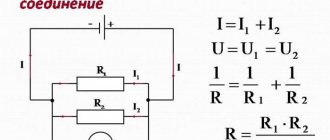
In this circuit, the current from the source is divided into two, inversely proportional to the resistance of the resistors.
In addition to regulating current, resistors are used in voltage dividers. In this case, Ohm's law is used again, but in a slightly different form:
U=I∙R (2)
From formula (2) it follows that as the resistance increases, the voltage increases. This property is used to construct voltage divider circuits.
From the diagram and formula (2) it is clear that the voltages across the resistors are distributed proportionally to the resistances.
Atomizers for winding
Before purchasing an atomizer, it is better to seek advice from specialists, namely experienced vapers.
The most popular models among the vaping community are as follows:
- Kanger SubTank is a popular and highly advertised self-propelled clearomizer that has won many followers for its ability to use both factory and homemade coils. Recently a modification of this model was released - TopTank. The new version allows you to refill the electronic cigarette from above, thus without unscrewing the device from the mod.
- Kayfun is a Russian-made clear, which is created only for self-winding;
- Billow v2 – the main difference of this clearomizer is the ability to install two coils, and not, as usual, one.
- Zefirus is a double-coil clear of excellent quality, which is also loved by vapers for its ability to work with both homemade heads and factory ones.
- Velocity – unlike previous models, it is a drip device, not a clearomizer. That is, its device does not have a liquid tank. The refill must be dripped onto the spiral. Although not very convenient to use, Velocity will provide you with excellent taste and a lot of thick vapor.
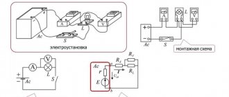
Illustration of resistors on diagrams
According to the standard, resistors are depicted as a rectangle with dimensions of 10 x 4 mm and are designated by the letter R. The power of the resistors is often indicated on the diagram. This indicator is depicted using oblique or straight lines. If the power is more than 2 Watts, then the designation is made in Roman numerals. This is usually done for wirewound resistors. Some countries, such as the USA, use different conventions. To facilitate repair and analysis of the circuit, the power of resistors is often given, the designation of which is carried out according to GOST 2.728-74.
Winding materials
To make a working atomizer, you need cotton wool and wire. Cotton wool is used as a wick, and a coil for an electronic cigarette is wound from wire. During the vaping process, the wick is wetted with liquid, then steam is produced under the influence of the heated coil and incoming air at the moment of inhaling.
Materials for the spiral
So, let's look at the commonly used materials for winding coils for electronic cigarettes:
- Nichrome - primarily attracts with its low price, as well as ease of creating windings;
- Fechral is an analogue of nichrome, but it does not contain nickel. The cost is even lower than that of nichrome, the service life and quality when used are also lower;
- Stainless steel is one of the cheapest and most accessible materials that has a long service life. Despite its advantages, it is used infrequently, since the material is not convenient for winding;
- Nickel - in addition to its high price, it also has high quality, so it is not recommended for beginners for “experience”;
- Titanium is not inferior in properties to nickel. As an advantage, it does not emit harmful substances when overheated, which other analogues cannot boast of. Despite this, experts say that the release of harmful substances begins when the device overheats at 600 °C, while mods do not heat up more than 350 °C.
Device Specifications
The main characteristic of a resistor is the nominal resistance Rн, which is indicated on the diagram near the resistor and on its body. The units of resistance are ohms, kiloohms and megaohms. Resistors are manufactured with resistances ranging from fractions of an ohm to hundreds of megaohms. There are many technologies for producing resistors, they all have advantages and disadvantages. In principle, there is no technology that would allow an absolutely precise production of a resistor with a given resistance value.
The second important characteristic is resistance deviation. It is measured as a percentage of the nominal R. There is a standard range of resistance deviations: ±20, ±10, ±5, ±2, ±1% and then up to ±0.001%.
The next important characteristic is the power of the resistors. During operation, they heat up from the current passing through them. If the dissipated power exceeds the permissible value, the device will fail.
Resistors change their resistance when heated, so for devices operating in a wide temperature range, another characteristic is introduced - the temperature coefficient of resistance. It is measured in ppm/°C, that is, 10-6 Rн/°C (part per million of Rн per 1°C).
Types of conductors
The conductivity of an electric current by a substance is associated with the presence of free charge carriers in it. Their number is determined by their electronic configuration.
Read also: Water level sensor operating principle
To do this, you need a chemical formula of the substance, with which you can calculate their total number. The value for each element is taken from the periodic table of Dmitri Ivanovich Mendeleev.
Electric current is the ordered movement of free charge carriers, which are affected by an electromagnetic field. When current flows through a substance, a stream of charged particles interacts with the nodes of the crystal lattice, and part of the kinetic energy of the particle is converted into thermal energy. In other words, the particle “hits” the atom and then continues moving again, picking up speed under the influence of the electromagnetic field.
The process of interaction of particles with nodes of the crystal lattice is called electrical conductivity or resistance of the material. The unit of measurement is Ohm, and it can be determined using an ohmmeter or calculated. According to the property of conductivity, substances can be divided into 3 groups:
- Conductors (all metals, ionized gas and electrolytic solutions).
- Semiconductors (Si, Ge, GaAs, InP and InSb).
- Non-conductors (dielectrics or insulators).
Conductors always conduct electric current because they contain free electrons, anions, cations and ions in their atomic structure. Semiconductors conduct electricity only under certain conditions, which affect the presence or absence of free electrons and holes. Factors affecting conductivity include the following: temperature, illumination, etc.
Dielectrics do not conduct electricity at all, since there are no free charge carriers in their structure. When performing calculations, every radio amateur must know the dependence of resistance on certain physical quantities.
Parallel connection of resistors
In a parallel connection, all the beginnings of the resistors are connected to one node of the circuit, and the ends are connected to another. With this connection, the current branches out and flows through each device. The amount of current, according to Ohm's law, is inversely proportional to the resistance, and the voltage across all resistors is the same.
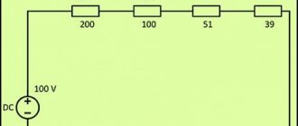
Before finding the current, you need to calculate the total conductance of all resistors using the well-known formula:
1/R=1/R1+1/R2+1/R3+1/R4=1/200+1/100+1/51+1/39=0.005+0.01+0.0196+0.0256= 0.06024 1/Ohm.
Resistance is the reciprocal of conductivity:
R=1/0.06024= 16.6 Ohm.
Using Ohm's law, find the current through the source:
I= U/R=100∙0.06024=6.024 A.
Knowing the current through the source, find the power of parallel connected resistors using the formula:
P=I2∙R=6.0242∙16.6=602.3 W.
According to Ohm's law, the current through resistors is calculated:
I1=U/R1=100/200=0.5 A;
I2=U/R2=100/100=1 A;
I3=U/R1=100/51=1.96 A;
I1=U/R1=100/39=2.56 A.
Using a slightly different formula, you can calculate the power of resistors in a parallel connection:
P1= U2/R1=1002/200=50 W;
P2= U2/R2=1002/100=100 W;
P3= U2/R3=1002/51=195.9 W;
P4= U2/R4=1002/39=256.4 W.
If you add it all up, you get the power of all resistors:
P= P1+ P2+ P3+ P4=50+100+195.9+256.4=602.3 W.
Types of winding
There are five types of coils. Many vapers are probably already familiar with them, but for beginners it will be useful to know what types of electronic cigarette coils there are.
- Microcoil is a small spiral, where the turns are located very close to each other. Due to its size, the coil is ideal for small clearomizers, while the heating area is large, which provides a lot of steam. When creating a microcoil, be careful not to cause a short circuit.
- Space coil is a standard coil in which the coils are separated by a small space (hence the name). This technology allows the cotton wool not to burn, but the liquid to be evenly saturated throughout the entire wick. Despite the convenient winding, the space coil will not give you much steam.
- “Pigtail” - a spiral is wound from two intertwined wires, which visually resemble a pigtail. Due to the increased heating area, the amount of steam and the quality of taste increases. However, there is one drawback - there is a possibility of “pulling out” not the vapor, but the smoking liquid.
- “Parallel” is an analogue of the previous type of winding, only two wires in a spiral run parallel, and are not intertwined into a pigtail. Guarantees a large amount of steam. When replacing the coil in an electronic cigarette, the main difficulty is securing the ends of the two parallel wires.
- Art coils - the main feature of this type of winding is the patterned weaving, which is more of an art than a way to wind a spiral. Only “gurus” in their field know the technique of art coils. The large heating area gives an amazing effect in the form of a huge amount of steam and a pronounced taste of the liquid.
Mixed compound
Circuits with a mixed connection of resistors contain a series and parallel connection. This circuit can be easily converted by replacing the parallel connection of resistors with a series one. To do this, first replace the resistances R2 and R6 with their common R2.6, using the formula given below:
R2.6=R2∙R6/R2+R6.
In the same way, two parallel resistors R4, R5 are replaced with one R4.5:
R4.5=R4∙R5/R4+R5.
The result is a new, simpler circuit. Both diagrams are shown below.
The power of resistors in a circuit with a mixed connection is determined by the formula:
P=U∙I.
To calculate using this formula, first find the voltage at each resistance and the amount of current through it. Another method can be used to determine the power of the resistors. The formula used for this is:
P=U∙I=(I∙R)∙I=I2∙R.
If only the voltage across the resistors is known, then another formula is used:
P=U∙I=U∙(U/R)=U2/R.
All three formulas are often used in practice.
Winding process
How to wind a coil for an electronic cigarette? Let's look at this issue using a standard coil as an example. Art coils are complex in their implementation, so it’s unlikely to be possible to explain anything briefly.
Here is a list of tools that we will need in our work:
- scissors;
- tweezers (preferably ceramic);
- pliers;
- screwdriver (it can also be used for winding);
- wire cutters
So, let's take a closer look at the process itself:
- In any task, hygiene is important, so it is necessary to wash your hands and tools. First of all, this is necessary so that the cotton wool for the wick does not absorb foreign aromas;
- If the wire material twists or springs, you need to burn it (you can use a gas stove or a lighter). This paragraph does not apply to nickel and titanium. Under no circumstances should you burn them - you will not only reduce the quality, but also contribute to the release of harmful substances;
- The wire must be degreased with alcohol. If you are using nickel or titanium, this step must be performed before winding, as they are not allowed to be burned through;
- Take a screwdriver or a special winding tool and start winding the wire around. Depending on the type of winding chosen, the turns should be made tightly to each other or leave a space of about 1 mm between them. Don’t worry if they turn out uneven, it will all be corrected later;
- After a sufficient number of turns have been made, they can be compressed with pliers and then slightly stretched;
- Now we can proudly declare that the spiral is ready. Let's proceed to installing this spiral on the base of the clear. Unscrew the coil screws and insert the ends of the coil under them. Then tighten the bolts back. Using a screwdriver, adjust the spiral again so that it is positioned exactly in the center. Make sure that its edges do not come into contact with the walls of the base. The ends of the wire should also not touch the base elements; excess must be removed with wire cutters. Otherwise, a short circuit may occur;
- Important! The higher the spiral is in relation to the lower hole, the greater the blow to the throat, and vice versa;
- Press the hover button to burn through the already installed coil. It should turn red evenly from the center to the edges. If any area does not heat up, run ceramic tweezers over it;
- The final step is to place the cotton wool or other material of your choice into the spiral. The cotton wool should pass freely from one side to the other;
- Cut off the long tails, leaving a little in reserve;
- Hide the remaining ends inside the clearomizer base. Make sure that the cotton wool does not get on the threads.
Calculation of circuit parameters
Calculation of circuit parameters consists of finding unknown currents and voltages of all branches in sections of the electrical circuit. Having this data, you can calculate the power of each resistor included in the circuit. Simple calculation methods were shown above, but in practice the situation is more complicated.
In real circuits, resistors are often connected with a star and a delta, which creates significant difficulties in calculations. To simplify such circuits, methods have been developed for converting a star into a triangle, and vice versa. This method is illustrated in the diagram below:
The first circuit includes a star connected to nodes 0-1-3. Resistor R1 is connected to node 1, R3 is connected to node 3, and R5 is connected to node 0. In the second diagram, triangle resistors are connected to nodes 1-3-0. Resistors R1-0 and R1-3 are connected to node 1, R1-3 and R3-0 are connected to node 3, and R3-0 and R1-0 are connected to node 0. These two schemes are completely equivalent.
To move from the first circuit to the second, the resistances of the triangle resistors are calculated:
R1-0=R1+R5+R1∙R5/R3;
R1-3=R1+R3+R1∙R3/R5;
R3-0=R3+R5+R3∙R5/R1.
Further transformations come down to calculating parallel and series connected resistances. When the total resistance of the circuit is found, the current through the source is found using Ohm's law. Using this law, it is easy to find currents in all branches.
How to determine the power of resistors after finding all the currents? To do this, use the well-known formula: P=I2∙R, applying it for each resistance, we will find their power.
Basic laws
- with a series connection, a current of equal strength flows through each section of the circuit;
- the total resistance of the circuit when connected in series is equal to the sum of the resistance of all conductors;
- The voltage in the electrical network when connected in parallel is the same for each section;
In accordance with Kirchhoff's first law, the algebraic sum of the currents in a node is always equal to zero. Thanks to this, it is possible to obtain a formula for finding the equivalent circuit resistance if the resistance of each load is known. It has the following form: Ro =R1*R2 / R1+R2.
For series connection of loads, we apply Kirchhoff's second law. According to it, the sum of the EMF in a closed electrical circuit is equal to the sum of the voltage drops at each load. As a result, the total resistance can be determined using the following formula: Ro = R1 + R2.
You can also calculate the inductance for various types of coil connections. In the case of sequential, everything is quite simple, just use the following formula: Lo = L1 + L2. In fact, instead of two elements, you can install one with the corresponding inductance value.
When connecting coils in parallel, the situation becomes more complicated, since three options are possible:
- the magnetic fields of the coils do not intersect: Lo = L1 * L2 / L1 + L2;
- the coils are connected in the same direction and their fields intersect: Lo = L1 * L2-M 2 / L1 + L2 - 2 M;
- the intersection of the fields is observed with counter-connection: Lo = L1 * L2-M 2 / L1 + L2 + 2 M.
Today, you can often use an online calculator to calculate these and other indicators, for example, capacitor capacity.
Expert opinion
It-Technology, Electrical power and electronics specialist
Ask questions to the “Specialist for modernization of energy generation systems”
Series and parallel connection of conductors ℹ️ formulas Let us recall that the positive terminal of the source is indicated by a longer line, so that the current in this circuit flows clockwise. Ask, I'm in touch!
Speaker impedance, amplifier, etc. (+)
The general essence of the issue can be defined as follows: the resistance of acoustic systems is complex in nature and includes both an active component independent of the signal frequency and a reactive component dependent on the signal frequency. A real electrical audio signal is the sum of the harmonics of an alternating electrical current, so the impedance of a speaker system is highly dependent on the frequency of the input signal. The impedance values indicated in the passport data for speaker systems, as a rule, are indicated as average nominal ones, or in general you can see the impedance range, for example, Ohms. In other words, the comparison of the numbers of possible resistances indicated on the receiver and similar data on the speakers is very conditional, therefore, the logic of selecting components based on this principle may lead to the fact that your system will not work stably, and the range of selected products will be limited to a few possibly not models that are interesting to you. The actual resistance of many systems does not correspond to the declared value, and this parameter must be known for proper matching with the receiver and amplifier. The low impedance of the speakers requires the amplifier to supply a large amount of electric current to the load, and not all models are capable of this. Such a microcircuit, as a rule, is the same analog multi-channel amplifier, but it has a lot of limitations, primarily in terms of power supply. The circuitry and elements of such a hybrid amplifier are far from the Natural Sound concept; it is, first of all, an economy class, with all the ensuing consequences.
Video
Watch a video tutorial on how to wind a coil braid yourself without special tools.
Hello dear vapers and connoisseurs of delicious electronic vapor. If you have owned several devices, atomizers and box mods, then you have probably encountered “floating resistance” at least once in your practice. The answer to the question “Why does resistance fluctuate?” Every e-cigarette user probably wants to know. When you do coilbuilding yourself, this allows you to significantly save money, you can experiment and develop in this direction (change the number of turns, winding diameter, wire thickness, and so on). The result of creating coils yourself is good steam and just the pleasure of vaping.
What can you compare an atomizer with in order to make it clear what kind of thing it is? Most likely, the prototype of an atmoizer can be called a boiler. The principle of operation here will be the same. The evaporated liquid is supplied to the coil through cotton or other conductors, depending on the type of atomizer selected, and by pressing the start button, vaporization occurs and you inhale the vapor.
The number and diameter of the turns of the heating material determines the resistance. The lower the resistance, the more steam your devices will generate, but the service life of the winding will decrease. There are mainly several reasons for this:
1) Strong heating of the coil leads to the formation of carbon deposits; 2) The wire may burn out due to high temperatures
Correct selection of resistance ensures long-term and trouble-free operation of the atomizer. It looks like you did everything right, burned the coil, and prepared the atomizer for vaping. But as soon as you poured the liquid, the display began to frantically show different resistance values of the spiral you created. So why can the atomizer resistance jump?
1) Weak contact. If the ends of the spiral are not sufficiently tightened with the mounting screws, get ready for “floating resistance” 2) The resistance of the wound spiral is not suitable for the battery pack; 3) Weak connection between the contacts of the atomizer and the battery pack; 4) Fault in the board design.
In order to deal with the “floating resistance”, you first need to use a proven tester, if you have one in your arsenal. Instead of a tester, you can try checking the resistance of the coil on a friend’s box mod, and if this is not possible, then use a coil calculator, which Today there are a lot on different resources.