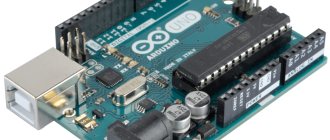
- Onboard USB port
- “Raw” input to the microcontroller 5V
- Stabilized Vin
As for the ground ( GND ), they are all connected to each other and are simply duplicated on the board, this needs to be remembered. 3.3V , 5V and GND pins provide power for the sensors and modules, but let's look at the features.
USB powered
USB power is the worst way to power an Arduino project. Why? Along the +5V power line from USB there is a diode that performs a protective function: it protects the computer’s USB port from high current consumption by the components of the Arduino project or from a short circuit (short circuit), which can occur by accident/crankiness of those who like to pick breadboards. A short circuit lasting less than a second will not have time to seriously damage the diode and everything can be fine, but a long short circuit turns the diode into a fuse, releasing a cloud of blue smoke and saving the computer port from the same fate.
By the way, Arduinos from the manufacturer Robotdyn have a self-restoring fuse instead of such a crutch with a suicide diode.
A low-current diode has another unpleasant feature: the voltage across it drops, and the greater the current consumption of the circuit, the more the supply voltage drops. Example: a bare arduino without anything consumes about 20 mA, and from 5 Volts on the USB after the diode we are left with about 4.7 Volts. Why this is bad: the reference voltage when using an ADC is extremely unstable, you don’t know what you are measuring (yes, there is a way to measure the reference voltage, but you need to do it manually). Some hardware is sensitive to supply voltage, for example LCD displays: when powered by 5V they are bright and clear, but at 4.7 volts (powered by USB) they noticeably lose brightness. If you move the servo drive or turn on the relay, the diode will drop even more and the display will almost go dark. Under short powerful loads (above 500-600mA), the microcontroller will restart as the voltage drops below the baseboard.
You will probably suggest replacing the diode with a jumper in order to power the circuit from USB with a higher current, for example from a powerbank. This also cannot be done, because the tracks on the board are not designed for high currents (the 5V track is very thin and goes across the entire board). I think it will be possible to remove 1-2 Amps from the 5V pin, but most likely the voltage will drop. Also, with a short circuit, you will most likely say goodbye to the track altogether. Power the power part of the circuit either separately or power the Arduino from the same source.
physical characteristics
Arduino Uno has the following dimensions: length 69 mm and width 53 mm. However, the power connector and USB connector protrude slightly from the PCB. Arduino Uno weighs about 25 grams. The board has 4 holes to allow it to be mounted on a surface. The distance between the pins is 2.5 mm, except for pins 7 and 8. There is 4 mm between them.
Schematic diagram
Schematic diagram of Arduino Uno
Food in Vin
the Vin pin (and GND ) is a more universal way to power an Arduino project; this pin supplies power to the onboard Arduino voltage regulator; on Chinese boards it is usually AMS1117-5.0. This is a linear stabilizer, which has its pros and cons. It allows you to power the Arduino and Arduino project from a voltage of 7-12 Volts (this is the recommended range, so you can power it from 5 to 20 Volts). The stabilizer is designed in such a way that it produces a good, even voltage with minimal ripple, but converts all excess voltage into heat. If you power the board and one miniature servo drive from 12 Volts, then when the drive is active, the stabilizer will heat up to 70 degrees, which is already noticeably hot. Based on some calculations from the datasheet, we can remember some numbers:
- At a voltage of 7 Volts (I have never seen such power supplies) in Vin you can remove from the 5V pin to 2A , more - overheating. Two lithium batteries will work great
- At 12 Volts on Vin, you can remove no more than 500mA without the risk of overheating the stabilizer.
Power supply to the Vin is possible only if the Arduino project (meaning the Arduino board and hardware connected to 5V and GND ) does not use powerful current consumers, such as servos, addressable LED strips, motors, etc. What is possible: sensors, sensors, displays, relay modules (no more than 3 simultaneously in the active state), single LEDs, controls. For projects with a powerful 5 Volt load, there is only a third method for us.
Power supply at 5V
5V pin (and GND ) is the best option to power the board and the Arduino project as a whole, but you need to be careful: the pin goes directly to the microcontroller, and it is subject to some restrictions:
- The maximum supply voltage according to the datasheet for the microcontroller is 5.5V. Anything higher will most likely disable the MK;
- The minimum voltage depends on the frequency at which the MK operates. Here is a line from the datasheet: 0 – 4 MHz @ 1.8 – 5.5V, 0 – 10 MHz @ 2.7 – 5.5V, 0 – 20 MHz @ 4.5 – 5.5V. What does this mean: most Arduino boards have a clock source of 16 MHz, that is, the Arduino will operate stably at ~4 Volts (20 MHz - 4.5V, 16 MHz - about 4V). There are versions of Arduino at 8 MHz, they will work quietly on a voltage of 2.5V.
Important: the supply voltage at pin 5V should not exceed 5.5V. Minimum voltage: 4V for 16 MHz boards (in my practice it worked stably from 3.5V), 2.5V for 8 MHz boards.
The most popular option is a USB charger from a smartphone, they are easy to get, the current range is from 500mA to 3A - they can handle almost any project. We cut off the plug and solder the wires to 5V and GND , having previously determined where the plus/minus is using a multimeter or by color: red is always plus, black is ground, with a red plus the ground can be white. If the ground is black, the plus can be white, just like that. We solder all the 5 Volt sensors/modules/consumers exactly there. Yes, it’s not very convenient to solder, but with a known circuit, you can carefully collect all the power into separate strands and solder them. An example in the photo below. The power source there is a separate micro-usb socket, a green board immediately above the display.
Turning off microcontroller components
This method is suitable in cases where the microcontroller must perform a number of specific actions with the same peripheral for a long time.
Any microcontroller is a set of different modules, and all modules have the ability to turn power on and off.
In order to use this method, you need to include the power.h library:
#include
After this, we will have access to a number of functions for enabling and disabling individual microcontroller peripheral modules:
| Shutdown function | Power-on function | Module description |
| power_aca_disable() | power_aca_enable() | Port A analog comparator. |
| power_adc_disable() | power_adc_enable() | ADC. |
| power_adca_disable() | power_adca_enable() | Port A ADC. |
| power_evsys_disable() | power_evsys_enable() | EVSYS module |
| power_hiresc_disable() | power_hiresc_enable() | Port C HIRES module. |
| power_lcd_disable() | power_lcd_enable() | LCD module. |
| power_pga_disable() | power_pga_enable() | Amplifier with programmable gain. |
| power_pscr_disable() | power_pscr_enable() | Reduced power controller. |
| power_psc0_disable() | power_psc0_enable() | 0 Power level controller. |
| power_psc1_disable() | power_psc1_enable() | 1 Power level controller. |
| power_psc2_disable() | power_psc2_enable() | 2 Power level controller. |
| power_ram0_disable() | power_ram0_enable() | SRAM block 0. |
| power_ram1_disable() | power_ram1_enable() | SRAM block 1. |
| power_ram2_disable() | power_ram2_enable() | SRAM block 2. |
| power_ram3_disable() | power_ram3_enable() | SRAM block 3. |
| power_rtc_disable() | power_rtc_enable() | Real time clock module. |
| power_spi_disable() | power_spi_enable() | SPI interface |
| power_spic_disable() | power_spic_enable() | Port C SPI Interface |
| power_spid_disable() | power_spid_enable() | Port D SPI Interface |
| power_tc0c_disable() | power_tc0c_enable() | Timer/Counter 0 Port C |
| power_tc0d_disable() | power_tc0d_enable() | Timer/Counter 0 Port D |
| power_tc0e_disable() | power_tc0e_enable() | Timer/Counter 0 Port E |
| power_tc0f_disable() | power_tc0f_enable() | Timer/Counter 0 Port F |
| power_tc1c_disable() | power_tc1c_enable() | 1 Port C Timer/Counter |
| power_twic_disable() | power_twic_enable() | Port C I2C interface |
| power_twie_disable() | power_twie_enable() | E port I2C interface |
| power_timer0_disable() | power_timer0_enable() | Timer 0 |
| power_timer1_disable() | power_timer1_enable() | Timer 1 |
| power_timer2_disable() | power_timer2_enable() | Timer 2 |
| power_timer3_disable() | power_timer3_enable() | Timer 3 |
| power_timer4_disable() | power_timer4_enable() | Timer 4 |
| power_timer5_disable() | power_timer5_enable() | Timer 5 |
| power_twi_disable() | power_twi_enable() | I2C interface |
| power_usart_disable() | power_usart_enable() | USART interface |
| power_usart0_disable() | power_usart0_enable() | USART 0 interface |
| power_usart1_disable() | power_usart1_enable() | USART 1 interface |
| power_usart2_disable() | power_usart2_enable() | USART 2 interface |
| power_usart3_disable() | power_usart3_enable() | USART 3 interface |
| power_usartc0_disable() | power_usartc0_enable() | USART 0 port C interface |
| power_usartd0_disable() | power_usartd0_enable() | USART interface 0 port D |
| power_usarte0_disable() | power_usarte0_enable() | USART interface 0 port E |
| power_usartf0_disable() | power_usartf0_enable() | USART interface 0 port F |
| power_usb_disable() | power_usb_enable() | USB interface |
| power_usi_disable() | power_usi_enable() | USI interface |
| power_vadc_disable() | power_vadc_enable() | ADC voltage module |
| power_all_disable() | power_all_enable() | All modules |
The availability of these functions will be determined by the type of microcontroller used and what peripherals are present in it. In order not to study the documentation for each specific controller, you can disable all controller peripherals at startup using the power_all_disable() function, and then separately enable the necessary modules.
For example, let's add sending data via the Serial port to our first program, and disable all other microcontroller peripherals:
#include #include #include long int i = 0; void setup() { power_all_disable(); //disable all peripherals power_usart0_enable(); //enable USART0 for Arduino Mega power_timer0_enable(); //turn on timer 0 (it is necessary for normal operation of USART) Serial.begin(9600); //set the Serial speed to 9600 baud pinMode(LED_BUILTIN, OUTPUT); set_sleep_mode(SLEEP_MODE_PWR_DOWN); } void loop() { i++; Serial.println(i); //Send data to the Serial port delay(10); //We wait until sending data via USART is completed, otherwise the controller will go into sleep mode before the data has time to be sent completely digitalWrite(LED_BUILTIN, LOW); wdt_enable(WDTO_1S); WDTCSR |= (1 << WDIE); sleep_mode(); digitalWrite(LED_BUILTIN, HIGH); wdt_enable(WDTO_120MS); WDTCSR |= (1 << WDIE); sleep_mode(); } ISR (WDT_vect) { wdt_disable(); }
Power supply for “powerful” circuits
Summarizing and repeating everything said above, we will consider power options for projects with high current consumption. You can power a powerful project (LEDs, motors, heaters) from 5V like this: Arduino and the consumer are powered together from a 5V power source:
to power a powerful consumer from USB via the board ; there is a diode there, and the power traces are thin:
What should you do if you still want to power the project from USB, for example from a powerbank? It's convenient! Everything is very simple:
If you only have a 12V power supply, then I have bad news: the built-in stabilizer on the board will not pull more than 500 mA:
But if we want to power a 12V load , then there are no problems: the Arduino board itself consumes about 20 mA, and will easily operate from the on-board stabilizer:
Expansion cards
In stores specializing in robotics and microcontrollers, you can find the word “shield”. This is a special board that resembles an Arduino Uno. It matches it not only in shape, but also in the number of pins.
The shield is installed in terminal blocks, while part of them is used for shield functions, and the other part remains free for use in the project. As a result, you can get a multi-story “sandwich” of boards that implement many functions.
One of the most popular is Arduino Ethernet Shield. It is needed to communicate with Arduino via a regular network cable, twisted pair. There is an rj45 connector on it.
With such a shield, you can control your microcontroller over the network via a web interface, as well as read parameters from sensors without leaving your computer. There are projects using such a kit in home cloud storage, with a speed limit, after all, Atmega328 is rather weak for such tasks, and single-board computers like Raspberry pi are better suited for this.
Self-powered
It happens that it is necessary to provide autonomous power supply for the project, i.e. away from the outlet, let's look at the options. Also for these purposes, a lesson on energy saving and microcontroller sleep modes will be useful.
- Power supply to the USB The most ordinary Powerbank, maximum current - 500 mA (remember about the protective diode). The voltage on the pin is 5V and the high GPIO level in this case will be ~4.7V (again, remember about the diode). Attention! For most Powerbanks, the power is turned off when the load is less than 200mA, i.e. you can forget about energy saving;
- The maximum output current from the 5V pin is 500 mA!
- Any power supply/charger from a laptop with a voltage of 7-18 Volts
- For a stable 5V output - a lithium battery and a module that increases it to 5V. Such modules usually have a current reserve of 2A, and the module also consumes “in idle mode” - poor energy saving;
Using the Narcoleptic library
This library was created by Peter Knight and can be downloaded from https://code.google.com/p/narcoleptic/.
This library allows you to put the microcontroller into sleep mode for a certain time using one function - Narcoleptic.delay();. The argument of this function is the time in milliseconds - it is used in exactly the same way as the standard delay(); function.
Let's look at the same program as before, but using this library:
#include void setup() { pinMode(LED_BUILTIN, OUTPUT); } void loop() { digitalWrite(LED_BUILTIN, LOW); Narcoleptic.delay(1000); digitalWrite(LED_BUILTIN, HIGH); Narcoleptic.delay(120); }
As you can see, the code has become much simpler, and in cases where simple pauses between useful actions are needed, this library is the simplest and most convenient solution.
Arduino as a power source
An important point that follows from the previous ones: using the Arduino board as a power source for modules/sensors. There are two options here:
- Power supply of sensors and modules from 5V When powering the board from USB - maximum current 500 mA
- When powering the board in Vin - maximum current 2 A at Vin 7V, 500 mA at Vin 12V
- When the board is powered at 5V - the maximum current depends on the power supply
Description of board pins
The microcontroller has 14 digital pins , they can be used as input or output. Of these, 6 can output a PWM signal. They are needed to regulate load power and other functions.
| Arduino pin | Addressing in a sketch | Special appointment | PWM |
| Digital pin 0 | 0 | RX | |
| Digital pin 1 | 1 | TX | |
| Digital pin 2 | 2 | Interrupt input | |
| Digital pin 3 | 3 | Interrupt input | PWM |
| Digital pin 4 | 4 | ||
| Digital pin 5 | 5 | PWM | |
| Digital pin 6 | 6 | PWM | |
| Digital pin 7 | 7 | ||
| Digital pin 8 | 8 | ||
| Digital pin 9 | 9 | PWM | |
| Digital pin 10 | 10 | SPI (SS) | PWM |
| Digital pin 11 | 11 | SPI (MOSI) | PWM |
| Digital pin 12 | 12 | SPI (MISO) | |
| Digital pin 13 | 13 | SPI (SCK) A built-in LED is additionally connected to the output |
The PWM signal is called via the AnalogWrite command (pin number, value from 0 to 255 ). To work with analog sensors, there are 6 analog inputs/outputs.
| Pin | Addressing in a sketch | Special appointment |
| Analog pin A0 | A0 or 14 | |
| Analog pin A1 | A1 or 15 | |
| Analog pin A2 | A2 or 16 | |
| Analog pin A3 | A3 or 17 | |
| Analog pin A4 | A4 or 18 | I2C (SCA) |
| Analog pin A5 | A5 or 19 | I2C (SCL) |
They can also be used as digital ones.
The analog signal is processed by a 10-bit analog-to-digital converter (ADC), and when read, the microcontroller produces a numerical value from 0 to 1024 . This is equal to the maximum value that can be written in 10 bits. Each of the pins is capable of delivering a constant current of up to 40 mA.
The circuit diagram of the board looks like this (click to enlarge):
Interference and protection against it
If there are powerful consumers in the same power circuit with the Arduino, such as servos, addressable LED strips, relay modules, etc., noise may occur on the power line, leading to strong measurement noise from the ADC, and more powerful interference can cause interrupts and even change states pins, disrupting communication across various communication interfaces and introducing errors into sensor readings, displaying nonsense on displays, and sometimes it can even lead to the controller rebooting or freezing. Some modules can also freeze, reboot and fail if the power supply is poor, for example, a bluetooth module can easily freeze and hang until the system is completely rebooted, and rf24 radio modules will not work at all with a “noisy” power supply.
Moreover, interference can come from unexpected places - through the air, for example from an electric motor, the inductive surge is caught by wires and does all sorts of things to the system. What to do? “Big guys” in real industrial devices do a lot to protect against interference; entire books and dissertations are devoted to this. We will look at the simplest thing you can do at home on your knee.
- Power the logical part (Arduino, low-current sensors and modules) from a separate low-noise 5V power supply, that is, separate the power supply of the logical and power parts, or even better, feed the Vin pin from a 7-12V power supply, since the linear stabilizer gives a very good smooth voltage. For the correct operation of devices that are powered separately (motor drivers, drives), you need to connect the grounds of the Arduino and all external devices;
- Place capacitors to power the board , as close as possible to the 5V and GND pins: electrolyte 6.3V 100-470 uF (µF, the capacitance depends on the quality of the power supply: in case of strong voltage drops, install a larger capacitance; in case of slight interference, 10-47 µF is enough) and ceramic by 0.1-1 uF. This will smooth out noise even from servos;
- For “remote” elements of the system on the wires (buttons, knobs, sensors), twist the wires into a pigtail , mainly with the ground. It’s even better to use shielded wires; the screen will naturally be GND. This way we protect ourselves from electromagnetic interference;
- Connect all grounds with one thick wire and, if possible, ground to a central ground;
- The metal and grounded body of the device (or simply wrapped in foil?), to which all components of the circuit are grounded, is the key to the complete absence of interference and interference through the air.
An LC filter consisting of an inductor and a capacitor can handle noise filtering even better. The inductance should be taken with a nominal value in the region of 100-300 μH and with a saturation current greater than the load current after the filter. The capacitor is an electrolyte with a capacity of 100-1000 uF, depending again on the current consumption of the load after the filter. It is connected like this, the closer to the load, the better:
You can read more about calculating filters here.
Inductive emissions
In practice, the most vile interference usually comes when switching an inductive load using an electromagnetic relay: it is very difficult to protect yourself from such interference, because it comes along the ground, that is, even separate power supply of the project will not save you. What to do?
- For chains direct current Be sure to install a powerful diode in reverse parallel to the load, as close as possible to the relay terminals. The diode will accept (close) the inductive surge from the motor/coil;
- There, on the relay terminals, you can put an RC circuit, called in this case a spark-extinguishing circuit: a 39 Ohm 0.5 W resistor, a 0.1 uF 400V capacitor (for a 220V circuit);
- AC networks, use a solid-state relay (SSR) with a Zero-cross detector, also called “silent” relays. If in the AC circuit instead of a relay there is a triac with an optocoupler, then the optocoupler must again be used with a zero detector, such an optocoupler, like the SSR zero-cross, will turn off the load at the moment when the voltage in the network passes through zero, this minimizes everything emissions.
You can read more about spark arresting circuits in this manual.
Main Stupid Question
Beginners in electronics who do not know Ohm’s law very often have questions like: “what current can be used to power the Arduino,” “what current can be supplied to the Arduino,” “won’t my Arduino burn out from the 12V 10A power supply,” “,” how many Amperes can be supplied to Arduino” and other nonsense. Remember: you cannot supply Amps, you can only supply Volts, and the device will take as many Amps as it needs . In the case of Arduino, the bare board will take 20-22 mA, either from the 5V pin or from Vin. The current indicated on the power supply is the maximum current that the power supply can supply without damage/overheating/voltage sags . You should worry not about the Arduino, but about the rest of the hardware that is in the circuit and is powered by the power supply, as well as the power supply itself, which may not be able to handle your load (motor, LEDs, heater). The total current consumption of the components should not exceed the capabilities of the power supply, that's the point. And even if the power supply is at least 200 Amperes, the components will take exactly as much as they need , and you will have “current reserve” to connect others. If the device is powered by voltage, then remember a very simple thought about the maximum current of the power source: you can’t spoil the porridge with oil .
Volts, amperes, capacity
Let's start with the basic concepts of the world of electricity: Volts and Amperes (read more about this in this lesson). Volts are voltage, also known as potential difference. The voltage is determined by the power source, such as a battery or power supply. Amperes - the current strength in the circuit, shows how much electrical energy is “consumed”. The current in the circuit is set by the consumer. (Note: the above is true for a voltage source, which is any battery/accumulator or a regular power supply. The current source can be a special charger or an LED driver; you cannot power the circuit intended for the voltage source from them - it will immediately burn out). Consumed and stored energy is usually calculated in Amp*hours; it works as follows: let’s say the battery capacity is 1 A*h (Ampere*hour). This means that such a battery will be able to deliver a current of 1 Ampere for one hour, while being completely discharged. If the current in the circuit is 0.5 A, the battery will last for 1 A*h / 0.5 A == 2 hours. The Arduino board consumes around 24 mA, that is, the same conventional battery can power it for 1000 mAh / 24 mA ~ 42 hours. When connecting consumers in parallel, as is usually the case in a circuit, the consumption current is summed up. If you add a backlit display to the “circuit” from the previous calculation, which will consume another 30 mA, then such a circuit will work from the same battery 1000 mAh / (24+30 mA) ~ 18.5 hours.
Important Pages
- GyverKIT kit - a large Arduino starter kit of my design, sold in Russia
- Catalog of links to cheap Arduins, sensors, modules and other hardware from AliExpress from trusted sellers
- A selection of libraries for Arduino, the most interesting and useful, official and not so
- Complete documentation on the Arduino language, all built-in functions and macros, all available data types
- A collection of useful algorithms for writing sketches: code structure, timers, filters, data parsing
- Video lessons on Arduino programming from the “Arduino Engineer's Notes ” channel are some of the most detailed in RuNet
- Support the author for his work on the lessons
- Feedback - report an error in the lesson or suggest an addition to the text ( [email protected] )
5 / 5 ( 29 votes)
Uno sizes
Arduino Uno R3 is the most popular board based on the ATmega328 processor. Depending on the specific model of the board in this line, various microcontrollers are used; at the time of writing, the most common version is R3.
The board is used for training, development, and creation of working prototypes of devices. Arduino, at its core, is an AVR microcontroller with simplified programming and development capabilities. This was achieved using a specially prepared bootloader flashed into the MK’s memory and a proprietary development environment.
Arduino Uno board
The dimensions of the board are shown in the diagram below. The overall dimensions of the Uno are 53.4 mm by 68.6 mm .