It is impossible to determine the resistance value of a resistor “by eye” by size. Various technologies are used for their production; they can have different sizes with the same characteristics. So size is definitely not an indicator in this matter. To determine the value, there is a marking of resistors. Moreover, it may be alphanumeric, or perhaps color. We will talk about what all these letters, numbers, and colored stripes mean.
The alphanumeric marking of permanent resistors is a legacy of the USSR. Now this method is not used, but the element base still exists; there are many such elements in old equipment that is many years old, but which still works. When repairing these “rarities,” you often have to change the resistance, and for this you will have to deal with this type of marking.
There are two types of resistor markings - alphanumeric and color
More “modern” resistors are color-coded (sometimes called “colored”). Stripes of a certain color are painted on the body of the element. Depending on the number of stripes and their position, the nominal value is calculated and the tolerance (permissible error in the resistance value) is determined. Let's figure out how to read the markings. It can be applied to any type of resistor, so it’s useful to understand the topic.
Alphanumeric marking of resistors
The simplest in terms of evaluation is the Soviet resistor, its power rating is marked directly on the case with the marking MLT-1 and so on, where the unit of measurement is power, and MLT is the type of resistors most popular in Soviet times, and this abbreviation means that the resistor is M - metal film, L-varnished, T-heat-resistant. The power of such resistors depends on their size; the larger the resistor, the more power it can dissipate. These resistors are already an endangered species; they can be found in old electronic equipment.
, the unit of measurement of resistance, like others, is Ohms, they are designated as R and E. The exact power size is indicated by the additional letter “ K ” - kilo-ohms or the letter “ M ” - mega-ohms; the measurement system here is quite simple. For example: 33E is 33 Ohms, and 47K is 47 kOhms, respectively, 1M2 is 1.2 Megaohms and so on.
If there is only a number without a letter, then they mean that this resistance is in Ohms, and the tolerance with this designation is 20%. For example, if the number 10 is written, then you have a resistor with a resistance of 10 ohms, and the tolerance is 20%.
Examples of alphanumeric markings of resistors
3E9I or 3R9 means that the resistance is 3.9 Ohms, tolerance 5%
2K2I means that the resistance is 2.2 kOhm, tolerance 5%
5K1S means that the resistance is 5.1 kOhm, tolerance is 10%
Description of MLT resistors
A fixed resistor is used to ensure the normal operation of electrical circuit components as a current limiter, voltage divider, shunt or load; it is mounted in a wall-mounted manner.
What they look like
A metal film resistor consists of a ceramic tubular base coated with a thin layer of metallized film of a special resistive material. The value of the resistance ratings depends on the composition of the film and the number of turns of the spiral cut on a ceramic base.
Along the edges of the tubular base there are brass caps with silver-plated copper wire leads for installation in the circuit.
To protect against mechanical damage, the current-carrying layer is covered with moisture-resistant organic enamel with markings applied to it.
Most often, the enamel coating is red with alphanumeric or color markings applied to it.
What features do
According to the manufacturing method, MLT resistors can be either with a spiral groove or unthreaded. The most reliable are considered to be non-threaded ones, the ohmic resistance of which is up to 2 kOhm.
During operation, all resistors heat up, dissipating the generated heat. The location of low-power metal-film resistors next to more powerful ones causes intense heating and premature failure of the element - the location of resistive elements at a distance of two diameters between them is considered optimal.
The operational reserve of Soviet resistances is large, but they are subject to aging - during long-term storage in a heated room, the conductive layer oxidizes and crystallizes, and the protective coating hardens.
When and by whom were they produced?
Metal film resistors were produced from 1964 to 1993 - these were the most popular resistors in the USSR, which are still used by many radio amateurs.
Soviet industrial plants producing metal film resistors - Nizhny Novgorod (now NPO ERKON), Kermet in the Penza region.
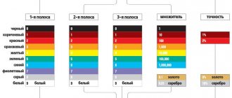
Color coding of resistors
Color coding has made the marking process a little easier on a mass production scale, but has also confused some hams, but it's actually quite simple.
The starting point of the report is usually considered to be a gold stripe or a silver one - this is the initial link, and it is not counted; it is necessary to rotate it and orient it so that the colored stripes start on the left side.
Next it reads the number by stripes:
- 0-black;
- 1-brown;
- 2-Red;
- 3-Orange;
- 4-Yellow;
- 5-Green;
- 6-Blue;
- 7-Purple;
- 8-Grey;
- 9-White.
The third bar in the barcode has a slightly different meaning - it measures the number of zeros that need to be added to the resulting value. Therefore, black is 0, cinnamon is 1 zero (0), red is 2 zeros (00), and so on.
To simplify your calculations, you can use a program on your computer called Resistor 2.2 (link to download the program in the attachment). It will simplify the calculations and automatically show the power of the resistor when all strips are entered. Or use the resistor color coding calculator directly online.
Methods for determining resistor resistance
If there is no alphanumeric marking, you can use one of the following methods:
- The simplest method is to determine the denomination from the documentation. This is easiest to do if the part is purchased separately and has an accompanying document. If a resistor is part of an electrical apparatus, then its characteristics are indicated on the general electrical diagram either directly next to it (to the right or below) or below in the specification.
- If the resistor is a separate part, then its resistance can be measured with an ohmmeter or multimeter.
- It is possible to accurately identify a part contained in the device only after it has been desoldered.
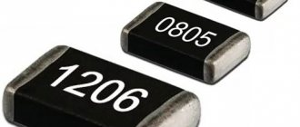
Marking of SMD resistors
SMD marking is a little more complicated; the dimensions of SMD resistors do not allow color rings to be applied to them or the value to be written. Therefore, they are marked with 3 or 4 numbers, except for resistors of size 0402 . The values of resistors of type 0402 can be found in the table. The rest have the following marking order.
Resistors with a tolerance of up to 10% are marked with 3 digits, where the first 2 digits are the resistor value, and the last one indicates the decimal value.
Example of SMD resistor markings:
3 Character Resistor
A resistor with the numbers 222 means 22 * 102 = 2200 Ohms or in other words 2.2 kOhms.
4 Character Resistor
Resistors with 4 characters have a tolerance of 1%, we calculate in the same way: 4422 is 442 * 2 * 102 = 44.2 kOhm
There are also smd resistors without markings, such resistors have a resistance of 0, they are needed simply to fill the empty space on the board, they are also called zero resistors.
The use of codes is currently the most popular way of marking SMD resistors, based on tabular codes for each indicator.
Internal structure
The main load-bearing element of the resistor is a substrate made of aluminum oxide (Al2O3). This material has good dielectric properties, but in addition it has very high thermal conductivity, which is necessary to remove the heat generated in the resistive layer into the environment.
Internal structure of the resistor.The main (but not all) electrical characteristics of a resistor are determined by the resistive element, which is most often a film of metal or oxide, for example, pure chromium or ruthenium dioxide, deposited on a substrate.
The composition, technology of application to the substrate and the nature of processing of this film are the most important elements that determine the characteristics of the resistor, and most often represent the manufacturing secret of the manufacturer.
Some types - wire resistors - use thin (up to 10 microns) wire made of a material with a low temperature coefficient of resistance (for example, constantan) wound on a substrate as a resistive material. In the latter case, the resistor value usually does not exceed 100 Ohms.
To connect the resistive element to the conductors of the printed circuit board, several layers of contact elements are used. The inner contact layer is usually made of silver or palladium, the intermediate layer is a thin film of nickel, and the outer layer is lead-tin solder.
This complex contact structure is designed to ensure reliable mutual adhesion of the layers. Its characteristics, such as reliability and current noise, depend on the quality of the contact elements of the resistor. The last element of the SMD resistor design is a protective layer, which ensures the protection of all elements of the resistor structure from the effects of environmental factors, and primarily from moisture. This layer is made of glass or polymer materials.
Table of SMD resistor codes and their values
| Code smd | Meaning | Code smd | Meaning | Code smd | Meaning | Code smd | Meaning |
| R10 | 0.1 Ohm | 1R0 | 1 ohm | 100 | 10 ohm | 101 | 100 Ohm |
| R11 | 0.11 Ohm | 1R1 | 1.1 Ohm | 110 | 11 ohm | 111 | 110 Ohm |
| R12 | 0.12 Ohm | 1R2 | 1.2 Ohm | 120 | 12 ohm | 121 | 120 Ohm |
| R13 | 0.13 Ohm | 1R3 | 1.3 Ohm | 130 | 13 ohm | 131 | 130 Ohm |
| R15 | 0.15 Ohm | 1R5 | 1.5 Ohm | 150 | 15 ohm | 151 | 150 Ohm |
| R16 | 0.16 Ohm | 1R6 | 1.6 Ohm | 160 | 16 ohm | 161 | 160 Ohm |
| R18 | 0.18 Ohm | 1R8 | 1.8 Ohm | 180 | 18 ohm | 181 | 180 Ohm |
| R20 | 0.2 Ohm | 2R0 | 2 ohm | 200 | 20 ohm | 201 | 200 Ohm |
| R22 | 0.22 Ohm | 2R2 | 2.2 Ohm | 220 | 22 Ohm | 221 | 220 Ohm |
| R24 | 0.24 Ohm | 2R4 | 2.4 Ohm | 240 | 24 ohm | 241 | 240 Ohm |
| R27 | 0.27 Ohm | 2R7 | 2.7 Ohm | 270 | 27 Ohm | 271 | 270 Ohm |
| R30 | 0.3 ohm | 3R0 | 3 ohm | 300 | 30 ohm | 301 | 300 Ohm |
| R33 | 0.33 Ohm | 3R3 | 3.3 Ohm | 330 | 33 Ohm | 331 | 330 Ohm |
| R36 | 0.36 Ohm | 3R6 | 3.6 Ohm | 360 | 36 Ohm | 361 | 360 Ohm |
| R39 | 0.39 Ohm | 3R9 | 3.9 Ohm | 390 | 39 Ohm | 391 | 390 Ohm |
| R43 | 0.43 Ohm | 4R3 | 4.3 Ohm | 430 | 43 Ohm | 431 | 430 Ohm |
| R47 | 0.47 Ohm | 4R7 | 4.7 Ohm | 470 | 47 Ohm | 471 | 470 Ohm |
| R51 | 0.51 Ohm | 5R1 | 5.1 Ohm | 510 | 51 Ohm | 511 | 510 Ohm |
| R56 | 0.56 Ohm | 5R6 | 5.6 Ohm | 560 | 56 Ohm | 561 | 560 Ohm |
| R62 | 0.62 Ohm | 6R2 | 6.2 Ohm | 620 | 62 Ohm | 621 | 620 Ohm |
| R68 | 0.68 Ohm | 6R8 | 6.8 Ohm | 680 | 68 Ohm | 681 | 680 Ohm |
| R75 | 0.75 Ohm | 7R5 | 7.5 Ohm | 750 | 75 Ohm | 751 | 750 Ohm |
| R82 | 0.82 Ohm | 8R2 | 8.2 Ohm | 820 | 82 Ohm | 821 | 820 Ohm |
| R91 | 0.91 Ohm | 9R1 | 9.1 Ohm | 910 | 91 Ohm | 911 | 910 Ohm |
| Code smd | Meaning | Code smd | Meaning | Code smd | Meaning | Code smd | Meaning |
| 102 | 1 kOhm | 103 | 10 kOhm | 104 | 100 kOhm | 105 | 1 MOhm |
| 112 | 1.1 kOhm | 113 | 11 kOhm | 114 | 110 kOhm | 115 | 1.1 MOhm |
| 122 | 1.2 kOhm | 123 | 12 kOhm | 124 | 120 kOhm | 125 | 1.2 MOhm |
| 132 | 1.3 kOhm | 133 | 13 kOhm | 134 | 130 kOhm | 135 | 1.3 MOhm |
| 152 | 1.5 kOhm | 153 | 15 kOhm | 154 | 150 kOhm | 155 | 1.5 MOhm |
| 162 | 1.6 kOhm | 163 | 16 kOhm | 164 | 160 kOhm | 165 | 1.6 MOhm |
| 182 | 1.8 kOhm | 183 | 18 kOhm | 184 | 180 kOhm | 185 | 1.8 MOhm |
| 202 | 2 kOhm | 203 | 20 kOhm | 204 | 200 kOhm | 205 | 2 MOhm |
| 222 | 2.2 kOhm | 223 | 22 kOhm | 224 | 220 kOhm | 225 | 2.2 MOhm |
| 242 | 2.4 kOhm | 243 | 24 kOhm | 244 | 240 kOhm | 245 | 2.4 MOhm |
| 272 | 2.7 kOhm | 273 | 27 kOhm | 274 | 270 kOhm | 275 | 2.7 MOhm |
| 302 | 3 kOhm | 303 | 30 kOhm | 304 | 300 kOhm | 305 | 3 MOhm |
| 332 | 3.3 kOhm | 333 | 33 kOhm | 334 | 330 kOhm | 335 | 3.3 MOhm |
| 362 | 3.6 kOhm | 363 | 36 kOhm | 364 | 360 kOhm | 365 | 3.6 MOhm |
| 392 | 3.9 kOhm | 393 | 39 kOhm | 394 | 390 kOhm | 395 | 3.9 MOhm |
| 432 | 4.3 kOhm | 433 | 43 kOhm | 434 | 430 kOhm | 435 | 4.3 MOhm |
| 472 | 4.7 kOhm | 473 | 47 kOhm | 474 | 470 kOhm | 475 | 4.7 MOhm |
| 512 | 5.1 kOhm | 513 | 51 kOhm | 514 | 510 kOhm | 515 | 5.1 MOhm |
| 562 | 5.6 kOhm | 563 | 56 kOhm | 564 | 560 kOhm | 565 | 5.6 MOhm |
| 622 | 6.2 kOhm | 623 | 62 kOhm | 624 | 620 kOhm | 625 | 6.2 MOhm |
| 682 | 6.8 kOhm | 683 | 68 kOhm | 684 | 680 kOhm | 685 | 6.8 MOhm |
| 752 | 7.5 kOhm | 753 | 75 kOhm | 754 | 750 kOhm | 755 | 7.5 MOhm |
| 822 | 8.2 kOhm | 823 | 82 kOhm | 824 | 820 kOhm | 815 | 8.2 MOhm |
| 912 | 9.1 kOhm | 913 | 91 kOhm | 914 | 910 kOhm | 915 | 9.1 MOhm |
Designation of variable resistors in diagrams
Resistor - what is it and what is it for?
The graphical appearance of the potentiometer is the designation of a rectangle with leads, with a line with an arrow resting on it. In the imported version, instead of a rectangle, there is a zigzag segment representing turns of wire. This designation can be found when calculating the value of R using an online calculator.
Graphic designation on diagrams
Marking of SMD resistors according to EIA-96
SMD resistors with greater precision and smaller dimensions have led to the creation of compact markings. The EIA-96 standard was invented . This standard is designed for resistors with a resistance tolerance of 1%.
This marking system consists of three symbols: the first two digits are the resistor value code, and the next symbol is the multiplier. We take the SMD resistor, look at the first 2 digits and find the corresponding resistance from the table, then look at the number and also look at the table by which to multiply by. It's quite simple.
02A = 200 Ohm ±1%
10S = 1 ohm ±1%
10C = 1000 ohms ±1%
Resistor marking table according to EIA-96 (value codes)
| Code | Number | Code | Number | Code | Number | Number | Number |
| 01 | 100 | 25 | 178 | 49 | 316 | 73 | 562 |
| 02 | 102 | 26 | 182 | 50 | 324 | 74 | 576 |
| 03 | 105 | 27 | 187 | 51 | 332 | 75 | 590 |
| 04 | 107 | 28 | 191 | 52 | 340 | 76 | 604 |
| 05 | 110 | 29 | 196 | 53 | 348 | 77 | 619 |
| 06 | 113 | 30 | 200 | 54 | 357 | 78 | 634 |
| 07 | 115 | 31 | 205 | 55 | 365 | 79 | 649 |
| 08 | 118 | 32 | 210 | 56 | 374 | 80 | 665 |
| 09 | 121 | 33 | 215 | 57 | 383 | 81 | 681 |
| 10 | 124 | 34 | 221 | 58 | 392 | 82 | 698 |
| 11 | 127 | 35 | 226 | 59 | 402 | 83 | 715 |
| 12 | 130 | 36 | 232 | 60 | 412 | 84 | 732 |
| 13 | 133 | 37 | 237 | 61 | 422 | 85 | 750 |
| 14 | 137 | 38 | 243 | 62 | 432 | 86 | 768 |
| 15 | 140 | 39 | 249 | 63 | 442 | 87 | 787 |
| 16 | 143 | 40 | 255 | 64 | 453 | 88 | 806 |
| 17 | 147 | 41 | 261 | 65 | 464 | 89 | 825 |
| 18 | 150 | 42 | 267 | 66 | 475 | 90 | 845 |
| 19 | 154 | 43 | 274 | 67 | 487 | 91 | 866 |
| 20 | 158 | 44 | 280 | 68 | 499 | 92 | 887 |
| 21 | 162 | 45 | 287 | 69 | 511 | 93 | 909 |
| 22 | 165 | 46 | 294 | 70 | 523 | 94 | 931 |
| 23 | 169 | 47 | 301 | 71 | 536 | 95 | 953 |
| 24 | 174 | 48 | 309 | 72 | 549 | 96 | 976 |
Potentiometers
A variable resistor (VR) and a potentiometer are two different definitions of one device. At the beginning of the development of radio electronics, it was believed that by changing the position of the moving contact on resistive coils with wire windings, the potential difference was measured. Therefore, two words: “potential” and “measurement” are included in the definition of a potentiometer. This is a variable resistor. Today there are many such components of electronic and electrical circuits, and their names are different. The voltage is adjusted with a potentiometer, and the current with a rheostat.
Important! The operating principle of such elements is the same. They change their output resistance depending on the position of the moving contact or brush, which is driven under the influence of external influences.
Non-wire
Resistors of the SP type belong to composite non-wire elements. They have the following design:
- base made of insulating material;
- film, current-conducting element;
- moving contact;
- axis with moving system.
Non-wire variable resistors also include SPO, VK, SPZ, TK.
A carbon conductive film is applied to the getinax plate (base). Its composition can be composite: bakelite resin and carbon black. The element leads are attached to the ends of the layer. To do this, it is coated with silver paste for contact pads. At specified angular intervals, a slider (moving contact) slides across the film, which is driven from the axis of the resistor.
For your information. The end of the axle is molded for ease of adjustment: a slot (slot) for a screwdriver or a recess for securing the handle.
Non-wire potentiometer device
Resistance may change as the angle of rotation changes. The angle varies from 0 to 2500.
Wire
In resistive variable elements of this type, high-resistance wire is used instead of a conductive film. It is laid in one layer turn to turn. The contact slides along these turns.
Structure of a wirewound variable resistor
A wirewound potentiometer consists of the following elements:
- frame for winding;
- winding;
- unit with an axis of rotation;
- movable brush.
Typically, frames are either bent from plates with wire already wound, or it is wound on rings. The plate frame is made of insulating material or metal.
Attention! Bent plate bases do not have precise geometric parameters, although they are easy to manufacture.
High precision when creating potentiometers is obtained using rings made of ceramic, metal or plastic. In this case, winding is carried out with special equipment - a shuttle, on which the required amount of wire is collected. The wire itself can be nichrome, manganin with enamel insulation.
Interesting. One such wire material is constantan alloy (59% Cu; 40% Ni; 2% Mn). It is an alloy of copper and nickel with the addition of manganese. Edward Weston invented it in 1888 for instrument coils. Constantan resistance is independent of temperature changes.
The wire insulation is ground to a depth of 0.25d. This is necessary for reliable connection of the brush with the winding during movement.
Appearance of the sliding edge
Including variable resistors in an electrical circuit
The connection diagram for such resistive elements depends on what they are used for. There are two types of connections to circuits:
- as a rheostat - an adjustable resistor to limit current;
- like a potentiometer - for dividing voltage (divider).
In the first case, the middle and extreme conclusions are taken, in the second - the middle and both extreme ones.
Attention! When the rheostat is turned on, the second free lead is soldered to the middle one to ensure more reliable contact.