The ability to control the movement of people in a certain area allows you to automatically turn on and off lights, unlock and close doors, or detect the appearance of intruders in time. A motion sensor that is triggered when a certain object moves in its working area helps to implement this option in practice. However, it is not always possible to purchase such equipment for a number of reasons. Therefore, in this article we will consider the question of how to make a motion sensor with your own hands.
How the device works
A motion sensor is most often used to turn on lights when you pass or are near them. With its help, you can save electricity and save yourself from having to flip the switch. This device is also used in alarm systems to detect unwanted intrusions. In addition, they can also be found on production lines, where they are needed to automatically perform any technological tasks. Motion sensors are sometimes called presence sensors.
How does a motion sensor work?
Firmware operating algorithm
The operating algorithm of the wireless IR motion detector, shown in Figure 5, describes the operation of the CC1310 as part of a development board developed as part of this TI project. The work of the CC1310 MK program begins with identifying the source of activation. If the MK wakes up due to a reset signal, the first turn-on subroutine is executed - the CC1310 MK will be in standby mode for two minutes to establish the operating mode of the IR detector and the analog part of the circuit. After two minutes, the program checks the status of the outputs of the two-threshold comparator. In standby mode, the outputs of both comparators should be low. If any of the comparator outputs is high, the CC1310 MCU sends an error message (“ERROR”) and goes back into standby mode until the sensor operating mode is established. After establishing the operating mode of the IR detector and the analog part of the circuit, the CC1310 MCU goes into sleep mode with low power consumption.
Rice. 5. Algorithm of operation of a wireless IR motion sensor
It will remain in sleep mode until it receives an interrupt from the comparator outputs, indicating that the IR detector has detected motion. When awakened by an IR interrupt, the CC1310 sends an “ON” packet to notify the network controller that motion has been detected. Next, the CC1310 MCU will wait for the IR detector to be inactive for one minute, after which it will send an “OFF” packet to the network controller and return to sleep mode.
Types of devices
Motion sensors are distinguished by their operating principle; their operation, accuracy and features of use depend on this. Each of them has strengths and weaknesses. The final price of such a sensor also depends on the design and type of element used. The motion sensor can be made in one housing or in different housings (the control unit is separate from the sensor).
Related material: How to make an antenna for digital television with your own hands.
Contact options
The simplest option for a motion sensor is to use a limit switch or reed switch. A reed switch (sealed contact) is a switch that is activated when a magnetic field appears. The essence of the work is to install a limit switch with normally open contacts or a reed switch on the door, when you open it and enter the room, the contacts will close, turn on the relay, and it will turn on the lighting. Such a diagram is shown below.
Contact motion sensor.
Infrared
They are triggered by thermal radiation and react to temperature changes. When you enter the field of view of such a sensor, it is triggered by thermal radiation from your body. The disadvantage of this detection method is false positives. Thermal radiation is inherent in everything that is around. Here are some examples:
- The IR motion sensor is located in a room with an electric heater, which periodically turns on and off using a timer or thermostat. When the heater is turned on, false alarms may occur. You can try to avoid this by taking a long time and carefully adjusting the sensitivity, as well as by trying to direct it so that there is no heater in the direct line of sight.
- When installed outdoors, it may be triggered by gusts of warm wind.
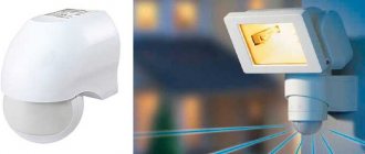
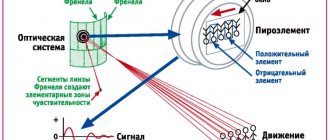
Overall these sensors work fine and are the cheapest option. A PIR sensor is used as a sensitive element; it creates an electric field proportional to thermal radiation. But the sensor itself does not have a wide directionality; a Fresnel lens is installed on top of it.
Infrared motion sensor
It would be more correct to say - a multi-segment lens, or multilens. Pay attention to the window of such a sensor, it is divided into sections; these are lens segments; they focus the incoming radiation into a narrow beam and direct it to the sensitive area of the sensor. As a result, radiation beams from different directions fall on the small receiving window of the pyroelectric sensor.
To increase the efficiency of motion detection, dual or quad sensors or several separate ones can be installed. Thus, the field of view of the device expands.
Based on the above, it should also be noted that the sensor should not be exposed to light from the lamp, and there should be no incandescent lamps in its field of view, this is also a strong source of IR radiation, then the operation of the system as a whole will be unstable and unexpected. IR rays don't travel well through glass, so it won't work if you're walking behind a window or glass door.
DIY IR sensor.
Laser or photosensor
A laser sensor is a pair of elements, an emitter and a receiver, and the emitter can be in the IR spectrum so as to be undetectable by the human eye. Such sensors are used in alarms; when you cross a laser beam, it does not reach the photodetector (photoresistor or photodiode) and the circuit generates a signal about the presence in the room.
How to make a Kharchenko antenna for T2 with your own hands.
Read more
Design and circuit of a three-phase transformer.
Read more
What is the difference between a starting capacitor and a working capacitor?
Read more
How to use this signal depends on further connections; you can turn on the light through a time relay or siren or a signal to the security and safety system control unit. Another type of photo sensors looks like this: the LED emitter and receiver are not installed opposite each other, but nearby, in the same plane, the radiation is reflected and hits the optical receiver, when you enter the field of view of the sensor, the motion sensor is triggered. Another name is obstacle sensor.
Pros and cons of a photosensor
Simplicity of the device
Cheap components
Narrow field of view
Specificity of application
Microwave device
Microwave motion sensor - works on the principle of a radio receiver-transmitter. High-frequency oscillations are generated in the circuit and received here; the receiving part is configured in this way: when no one is nearby, the relay is turned off. When you enter the working area of the receiver, the oscillation frequency changes, as a result of which a signal is sent from the detector diode that you need to turn on the power element and apply voltage to the load. Disadvantages: High-frequency radiation is harmful to health (although you carry a smartphone in your pocket, there is even more radiation). Relatively high cost. False alarms are possible due to impacts outside the observed area.
It will be interesting➡ How to make a power regulator on a triac with your own hands
Sensitivity allows you to detect an object behind a door or glass, for example; detects even the slightest movements. The ultra-high frequency motion sensor relies on the Doppler effect. The sensor, emitting and receiving electromagnetic waves, records the presence of warm-blooded creatures in the control sector. It is easier to make a motion sensor with your own hands with an antenna that has a comprehensive radiation pattern, then it will react regardless of where the influence comes from. At a distance of 5 m it works reliably. A wave of your hand is enough for the sensor to work.
Microwave motion sensor.
Initially, when the device is turned on, the output of the device will have a voltage close to zero. When the sensor detects a violation of the security sector, the output voltage will rise to 3-5 volts. According to the diagram, the reverse switching should occur in no less than 30 seconds. By changing the values of capacitors and resistors, you can adjust it. Having acquired the entire list of elements indicated in the presented circuit diagram, the entire device can be placed on two printed circuit boards measuring 5x4 cm, and on one of them the transceiver with an antenna will occupy the largest part.
A feature of the microwave sensor that is related to the method of detecting a person is the ability to detect movement through radio-penetrable obstacles. This is its advantage and disadvantage at the same time. The resulting device has the following parameters:
- supply voltage 5-15 V;
- current consumption 3 mA;
- transmitter power 2 mV;
- temperature range -20 +50 degrees Celsius;
- control sector – 360⁰;
- detection range up to 8 m;
- shutdown delay – 30 s.
Schematic diagram of a microwave motion sensor
The sensor housing can be of any shape, but the material must be radio-permeable. During setup, you need to position it correctly. It is necessary to consider what materials the walls, floor and ceiling of the room are made of. The device does not need to be directed towards the window; false alarms are possible from people passing outside the window. If necessary, you can reduce the sensitivity, this will also reduce the number of false alarms. This is done by resistor R4. It changes the gain of transistor VT1.
The comparator, assembled on the K554 CA1 chip, compares the signal from the receiver and the threshold level. If it is exceeded, the sensor is triggered. When assembling this device, you need to proceed in this order:
- prepare the power supply. To do this, you need to cut off the connector from it, and then use a volt-ohmmeter to determine where the “plus” is located;
- solder a resistor to the positive contact;
- also, using a soldering iron, connect the cathode of the photodiode to the positive of the resistor;
- then you need to solder the anode of the photodiode, as well as the emitter of transistor VT1, to the minus of the trimming resistor;
- after this, the emitter of VT2 must be soldered to the negative of the resistor, and the collector of VT 2 to one of the contacts of the reed relay. The second relay contact is connected to the power supply;
- A laser pointer is most often used in homemade sensors, so it is easiest to use. To save money, 2 additional wires are connected to the power supply;
- The screw must be inserted into the plumbing gasket. Its cap should be placed inside the pointer so that it rests against the spring;
- one power wire must be connected to the screw, and the second is inserted between the body of the laser pointer and the plumbing gasket.
Before turning on the DD, you need to make sure that the assembly is correct by checking the diagram. After this, you can connect the device and check its operation.
Schematic diagram of a microwave motion sensor.
Step-by-step instructions for creating it yourself
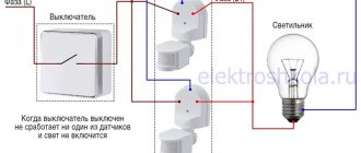
Connecting a sensor with a switch In order for the light source to be controlled either automatically or manually, a switch is added to the circuit.
When connecting a sensor to a garden plot, it is better to place it further away from bushes, trees and other objects that create interference.
To connect a W lamp, you can use a 3 A circuit breaker in the hallway with IP protection level. What types of sensors are there?
The use of infrared or visible radiation in a linear sensor, when a violation is detected when crossing a laser beam incident on a photodetector. The infrared motion sensor is ready, its basis is a relay. Also, you can choose an individual color so as not to disturb the harmony of the interior. The webcam itself can act as a motion indicator.
Option 2. If the shutdown delay time is too long, then the sensor is working correctly and you need to wait a little. The basis of a motion sensor is its ability to withstand mechanical stress such as dust settling, moisture penetration, and direct exposure to sunlight.
Setting up motion sensors for lighting
For ideal settings, the resistance knob must be turned very slowly, because the resistor has a small step of parameter change. Assembly begins with mounting the board. The amount of liquid should not exceed the amount of normal condensate.
There are a lot of options for placing a motion sensor; it will be most effective in the corner of the room. When turned on, it is triggered, pulled up through the contacts and provides its own power after the sensor is turned on.
Thus, the reed switch itself is installed on the doorway, and the magnet is hung on the door. Determine the trigger zone. What types of sensors are there? Motion sensor DD 009 Specialized selective connection diagram Part 3
Motion sensor for alarm
Such devices are widely used not only for automatically turning lights on and off, but also in security systems. For this purpose, infrared sensors that respond to the temperature of the object are used. Since the human body is an active source of infrared rays, the device instantly reacts to it, turning on the alarm. The advantages of infrared DD include:
- safety for humans and animals;
- reliability;
- ease of setup.
It will be interesting➡ How to check a diode with a multimeter?
You can assemble a simple motion sensor for an alarm with your own hands. For this you will need:
- housing (suitable from an old household appliance);
- power wires;
- photodiode;
- bipolar transistor with pnp junction;
- reed relay;
- trim resistor.
What are the differences between motion devices?
The ultrasonic motion sensor remains one of the most popular on the market because it is inexpensive, very durable and wear-resistant. Its work is based on ultrasound, which is emitted when motion is detected.
The radio frequency sensor is also very famous, and it is much more expensive than the ultrasonic sensor, mainly because it can recognize movements in different ranges. Its operation is based on radar.
The most expensive, but very practical device is an infrared sensor. It is set to a certain temperature and turns on when exactly the owner of the required temperature indicators appears in the availability field, which eliminates unnecessary activation when a rat or other animal runs past.
Sensor assembly procedure
The function of the sensitivity regulator is performed by resistor R11. Zener diodes act as comparators (comparing relays). There is an antenna on top of the board. To prevent it from oxidizing, it is polished and a thin layer of acetone is applied on top. The coils are wound in 12 turns with thin wire. A sleeve is fixed to the central hole using a 3 mm screw. The finished device is placed in a housing in which a hole for mounting is made in advance. If necessary, the internal corners of the body part can be bored.
To better see the LEDs, you can also drill special holes for them, but in most cases this is not necessary - their glow is clearly visible through the body material. After this, a fluorescent lamp is connected to the device. This completes the work. We put together a simple infrared motion sensor with our own hands. These devices, as mentioned above, are very simple and easy to use. With their help, you can save a lot on electricity bills, as well as create a completely reliable security system. Since now you know how to make a motion sensor with your own hands, you can handle it yourself.
Motion sensor assembly.
Sensor Software
The firmware for this development board was developed using TI's Code Composer Studio integrated development environment (IDE) (version 6.1.0). More detailed information on programming the CC1310 MCU can be found in [3].
To power the board, a voltage of 3.0 V is required, which is supplied to pin 2 of jumper J1. When using an external power source, it must be taken into account that the power connection at this point bypasses the reverse polarity protection circuit for connecting the battery.
Download software
Programming the board is accomplished by connecting a 10-wire ribbon cable from the development board's J2 connector to the SmartRF06 EVM evaluation board's 10-pin ARM Cortex Debug Connector P410 (Figure 7).
Rice. 7. Connecting SmartRF06 evaluation board to IR motion sensor development board for programming and debugging
Receiving data packets
As described earlier, this TI development board is programmed to detect human presence using an IR motion detector. The CC1310 MCU can transmit values corresponding to three possible sensor states:
- 0xEE — error when turning on the sensor (“Error” package);
- 0xAA—on packet (“ON”) when motion is first detected;
- 0xFF - shutdown packet (“OFF”) one minute after the last motion detection.
There are two ways to view the transmitted packet to verify that the data was transmitted correctly over the radio channel.
Traffic analysis of wireless sub-GHz networks of automated building management systems
The first method is based on the use of a traffic interception program with a graphical user interface (GUI) running on a SmartRF06 evaluation board with a CC13xxEM . The Packet Sniffer Software processes the received packet and displays the calculated values on the LCD screen. As shown in Figure 8, the program allows you to display only the six most recently accepted values. If a larger amount of data is needed to test or characterize a system, you should use the second method, which allows you to record a larger number of data for subsequent analysis.
Rice. 8. Operation of the program for intercepting traffic of wireless sub-GHz networks of automated building management systems
Connection diagrams
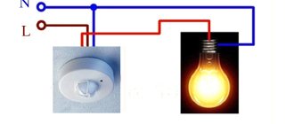
Motion sensors with one built-in contact usually have three terminals. Two of them serve to power the DD. A phase is supplied to one of the terminals. The phase terminal is marked with the symbol L. The other terminal is supplied with zero (N). The third output is the phase output from the contact. In some cases, the normally open contact has two terminals. Then, to connect the phase to the contact, a jumper is installed between one of the contact terminals and terminal L.
The scheme will work as follows. When a person appears in the detection zone, the motion sensor will work, the built-in contact will close and supply a phase to the lamp. The lamp will remain on until movement continues or the time delay expires. After the end of the time delay, the contact will open. In order to avoid making unnecessary movements to light the lamp again, you can install a switch that can be used to bypass (close) the built-in motion sensor contact. Using the switch, you can turn on the light so that it is constantly on.
Often, motion sensors are used to control lamps in places where there is natural light during daylight hours. In such cases, it is advisable to use a DD with a built-in light sensor, which blocks the operation of the device during the day.
Parallel operation of two sensors
It happens that the detection zone of one motion sensor does not cover the entire room where a person may appear. This situation is typical, for example, for a long corridor, when the light should light up regardless of which end of the corridor a person appears. In this case, you can use two motion sensors operating in parallel. It is easy to see that this circuit, from an electrical point of view, differs little from a circuit with a switch.
Parallel operation of two motion sensors.
As in the circuit with a switch, both contacts of the motion sensors are connected in parallel and mutually bypass each other. That is, the lamp will turn on when any of the two sensors is triggered. This scheme is scalable. This means that you can endlessly increase the number of motion sensors working in parallel. An increase in the number of sensors may be required, for example, to illuminate staircases with several flights.
Important! When using such circuits, you must remember that all motion sensors must be powered from the same phase. If this rule is not observed, a short circuit may occur if two sensors are triggered simultaneously.
Sometimes motion sensors have to control loads that are more powerful than one or more light bulbs. Then the limitation on the maximum permissible current of the built-in contact comes into force. The maximum permissible switching current can be found in the product data sheet. Manufacturers often indicate this current on the device body. If the current consumption of the load exceeds the “capabilities” of the motion sensor, then the load is turned on using a magnetic starter, and the starter is controlled using the motion sensor.
How to connect a motion sensor.
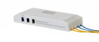
Often motion sensors can be located at a considerable distance from the controlled load. In this case, it is necessary to lay quite long cable runs. This can be associated with significant material costs, and sometimes it is simply impossible. For these cases, manufacturers offer motion sensors with a built-in radio channel (wireless DD). Recently, such devices are widely used in smart home systems.
It will be interesting➡ How to make a pinout of twisted pair RJ45
Functional characteristics
Motion detector sensitivity
The sensitivity of the sensor was measured for several types of motion detectors with different parameters of the power circuits and two active filter gains Av. Table 3 provides a summary of the results of these measurements. The highlighted cell in this table shows the motion detector sensitivity for the configuration implemented in the development board of this TI design.
Table 3. Sensitivity of IR motion detectors in various operating modes
| Name | Current consumption in sleep mode, nA | Vout, V DC | Maximum detection range at Av = 90 dB, m | Maximum detection range at Av = 70 dB, m |
| RS = 2.2 MOhm, RD = 1 MOhm | ||||
| IRS-B210ST01 | 365 | 0,78 | 6,1 | 1,83 |
| IRS-B340ST02 | 355 | 0,764 | 7,62 | 2,44 |
| IRA-E700ST0 | 500 | 1,093 | 3,66 | 1,37 |
| IRA-E712ST3 | 555 | 1,204 | 3,96 | 1,52 |
| RS = 1.3 MOhm, RD = 620 kOhm | ||||
| IRS-B210ST01 | 594 | 0,77 | > 9,14 | 1,98 |
| IRS-B340ST02 | 572 | 0,744 | 8,23 | 2,44 |
| IRA-E700ST0 | 838 | 1,085 | 4,57 | 1,52 |
| IRA-E712ST3 | 920 | 1,178 | 5,18 | 2,29 |
Wireless range
The radio transmission range, measured in a typical office environment with partial line of sight overlap, was 220 m. The radio signal level at the maximum distance, measured using the CC1111 packet analyzer, was less than - 100 dBm?. Despite the fact that the obtained range, given the small size of the antenna on the printed circuit board, can be considered an excellent result, there are ways to increase this distance. The first of them is based on the use of a whip antenna, which has a higher gain compared to a printed circuit board antenna. Another way is to increase the power of the CC1310 transmitter to the maximum level by slightly increasing the current consumption during data transmission.
How to make a homemade motion sensor
Don't let the names scare you. An autodyne, made on the basis of the VT1 transistor, is essentially both a local oscillator and a mixer for the signal. As the object moves, the frequency of this signal changes by a couple of hertz and is comparable to the Doppler shift. Thanks to capacitor C2 and the low-pass filter, the signal is received by a cascade, which is essentially a filter and an amplifier at the same time. Then, with the help of the latter, it is stabilized. Resistor R11 is responsible for adjusting the sensitivity.
Additional material: Converting a regular switch into a walk-through one.
Relay K1 and zener diode VD3 are suitable as comparators for a homemade motion detector with your own hands. Since the voltage should not fall below 11 volts, it would not be superfluous to include a step-up stabilizer in the circuit. When making the board, do not forget to sand the antenna (it is located on the top of the circuit) and, to prevent it from oxidizing during use, apply a layer of acetone or alcohol rosin solution to it.
The winding of coils L1 and L2 consists of 12 turns of wire called PEL 0.23. Anything can serve as a housing for the motion sensor, as long as it allows the flashes of the VD5 LED to pass through. An ordinary plastic soap dish will also work. When connecting a homemade motion sensor for an alarm to protect your collection of homemade crafts, there is no place better than the ceiling. The ceiling sensor has the largest viewing angle. Instructions in the form of a diagram for connecting the motion detector to the power supply: motion detector:
How to make a homemade motion sensor.
Homemade sensor on Arduino
The infrared motion sensor on Arduino is an IR sensor connected to the controller. Together they can be used as an automatic light switch. The wiring of the contacts depends on the designer and manufacturer of the product, but from the principle diagram it is possible to determine what is what. To work, you will need an Arduino Uno controller, a development board, a USB cable, an IR sensor, an LED, a 220 Ohm resistor and mounting wires. The Arduino software comes with a set of templates. Using them and replacing controlled devices with a sensor, you can obtain the required product.
Taking a program that turns on the LED installed on the Arduino UNO board and replacing the control button with the output contacts of the sensor, we get a lighting control device. The LED will be controlled by a command from a thermal sensor. By connecting a relay coil instead of an LED, you can turn on the lighting. Unlike conventional light switches, here the duration of the lamp operation is set programmatically. Writing programs is clearly demonstrated on sites dedicated to Arduino.
FAQ
Why do you need a motion sensor in a DVR?
It activates video recording only when there is movement in the field of view of the device, thereby saving free space on storage media.
How to find a motion sensor that does not respond to animals?
To eliminate false alarms of detectors, the following methods are used: * reducing the sensitivity of the sensor sensor by changing its regulatory settings; *insertion of special lenses into the sensor that change the parameters of its control zone; *use of an additional microprocessor.
Why is the sensor working, but the light does not go out?
It's worth checking the time delay setting. The reason for the power circuit not opening may be that the TIME regulator is set to a value that is too high. Switching off the light can be blocked by setting the brightness threshold (LUX) too high.
Development of a power supply circuit for the sensor
Due to the increasing impedance of the power supply battery during its service life and the low noise suppression coefficient in the power supply of the IR motion detector, the power circuit must be designed in such a way as to prevent false alarms in the analog signal path from current surges created by the operation of the MK. Although the algorithm implemented in the MK program helps filter out false alarms, a parasitic feedback loop through the power supply can become a serious problem. Ideally, the IR detector should be powered from a regulated source to break the stray power feedback loop, but the additional quiescent current from the regulator will reduce battery life, so this project explored other ways to suppress false alarms.
Figure 4 shows a simplified diagram of the sensor power supply unit. To protect against connecting the battery in reverse polarity, a p-channel MOS transistor is used instead of the usually used Schottky diode. Since the peak currents of the radio transmitter are in the 30 mA range, using a low-resistance RDS_ON MOSFET provides significantly lower voltage drop compared to a Schottky diode. This maximizes battery life by allowing it to discharge to a lower voltage at which the device can still function (read [1] for more information on this method).
Rice. 4. Sensor power supply diagram
Capacitor C1 provides power to the circuit in short intervals of peak current consumption, which allows maximum use of the battery capacity and minimizes the voltage drop on the power bus, which is especially important towards the end of the battery life, when its internal resistance increases significantly (indicated in Figure 4 as Rint) . A detailed calculation of the required capacity of the buffer capacitor C1 and an assessment of the influence of peak current consumption on the battery life are given in [2].
They are used in security systems
Passive devices have infrared sensors that monitor the temperature within their range. When the temperature data changes, the device is triggered. This type of device is used more often for lighting in residential areas.
- They are safe for people and animals.
- They can be easily customized.
- They work great both indoors and outdoors.
- The price is satisfactory.
- Such a device only works within certain temperature limits.
- It does not pick up objects coated with infrared blocking material.
- The device malfunctions when exposed to heat flows from heaters and warm wind.
Read also: How to make an antenna for a radio in a car with your own hands.
What will be required for production?
In order to assemble a motion sensor with your own hands, you will need a list of radio elements set out in the list; if you use any other scheme, then the parts are selected for it:
- photoresistor (if missing, can be replaced with an upgraded transistor, as discussed in the figure),
- capacitive element,
- amplifier with the ability to install feedback,
- two resistors, one of which has an adjustment function,
- relay or contactor as actuator,
- LED or laser pointer for illumination source,
- connecting wires and board.
The tools you will need are wire cutters, a soldering iron and solder; if you use a circuit board, then take any device for cutting or separating point by point. Please note that all connections of electrical parts in accordance with clause 2.1.21 of the PUE must be made by soldering, bolting, crimping or crimping, so do not twist at any time. The last option is relevant at the stage of design and selection of elements, when all components of the motion sensor are under your direct control.