May 26, 2016
engine management Texas Instruments article
The range of semiconductor components manufactured by Texas Instruments includes a wide range of driver chips for controlling all types of electric motors , which, as they improve, are increasingly used in a wide variety of equipment. The company offers solutions for creating drives operating in a wide range of currents and voltages, ensuring reliable and convenient operation of brushed , brushless and stepper motors with a full range of protections for current, voltage and temperature.
Electric motors are widely used in the modern high-tech way of life. This type of electromechanical drive is still one of the most common and in demand. Electric motors for various purposes are one of the main components of any production; they are widely used in office and home appliances, in monitoring and control systems for buildings and facilities. Electric motors are very widespread in modern transport. An even more exciting future lies ahead for electric motors in electric vehicles and robots.
With the development of technology, traditional engines are being improved and are finding new applications. Modern high-precision machine tools and robotics are unthinkable without electric motors with intelligent control systems. On land, in the air and under water, electric motors remain a widely used converter of electrical energy into mechanical energy.
Types of electric motors, control methods and difficulties encountered
First created in 1834 by the Russian scientist Jacobi, the converter of electrical energy into rotational motion was called an electric motor. Since then, it has been seriously improved - many new options have appeared, but the principles of electromagnetism used in its creation are still the basis of all modifications of modern electric motors.
A conductor with a current passing through it (Figure 1) creates a magnetic field around itself, the intensity (magnetic induction) of which is proportional to the number of turns, in the case of using a coil (N), and the magnitude of the current passing through it (I), where B is the magnetic vector induction, K – magnetic constant, N – number of turns, I – current strength.
Rice. 1. Electromagnetism is the basis of the operation of an electric motor
Changing the direction of the current also affects the direction of the magnetic field of the conductor.
In this case, a current-carrying conductor placed in an external magnetic field is acted upon by the Lorentz force, causing it to rotate. The direction of rotation is easily determined using the well-known right-hand rule for a current-carrying conductor in a magnetic field (Figure 2). The force (F) acting on a conductor in a magnetic field is equal to the product of the current strength (I) in the conductor by the field magnetic induction vector (B) and the length of the conductor (L). F = LIB.
Rice. 2. Movement of a conductor with current in a magnetic field (Lorentz force)
Windows program for engine
A ready-made program for Windows for a USB controller needs to be slightly modified. As a result, combinations for supplying voltage in different directions must be sorted out, we need to change the values on ports PB0, PB1, PB2, PB3, the following combinations are needed to start the engine 1010, 0110, 0101, 1001. Trying them in one direction - torsion in this direction , in the other - reverse torsion. 0000 - turns off the power, necessary at the end of the search, otherwise the engine will heat up. Now we are working on this program, so take it from the USB controller, the connection works there, by analogy you can do the rest as needed at home.
Brushed motors
Brushed DC motors (BDC or BDC, in TI terminology) are among the most common electromagnetic rotation mechanisms today.
In the magnetic field of a stator assembled from permanent magnets, a multi-section rotor with coils rotates, which are connected in pairs and alternately through switched collector lamellas on the rotor axis (Figure 3). The selection of a pair of activated coils is carried out on the basis of Lorentz's law in accordance with Gimlet's rule. The current source is always connected to coils whose magnetic field lines are shifted at an angle close to 90° relative to the stator magnetic field.
Rice. 3. Operating principle of a commutator motor (BDC)
Electric motors of this type often use a permanent magnet stator. They make it easy to adjust the rotation speed and are inexpensive.
A variant of a 2-winding electric motor of this type is also widely used, but with a stator winding instead of a permanent magnet. Such models have a large starting torque and can operate not only on direct current, but also on alternating current. Electric motors of this type are almost universally used in various household appliances.
The disadvantages of this BDC design include wear of the brush-commutator assembly during operation. In addition, due to sparking during commutation of individual rotor windings, an increased level of electromagnetic interference is observed, which does not allow the use of such motors in explosive environments.
A feature of BDC engines is also increased heating of the rotor, the cooling of which is difficult due to the design features of the engine.
Advantages of commutator motors:
- low cost;
- simple control system;
- 2-winding brushed motors with high torque and capable of operating on DC and AC.
Features of operation of commutator motors:
- brushes require periodic maintenance and reduce engine reliability;
- during the switching process, electrical sparks and electromagnetic interference occur;
- It is difficult to remove heat from an overheating rotor.
Connecting A4988 Stepper Motor Driver to Arduino UNO
Now that we have all the necessary information about the A4988 driver, we can move on to connecting it to our Arduino Uno.
Connections are quite simple. Start by connecting VDD and GND (next to VDD) to the 5V and minus pins on the Arduino. Connect the DIR and STEP input pins to digital pins No. 2 and No. 3 on the Arduino, respectively. Connect the stepper motor to pins 2B, 2A, 1A and 1B.
Warning:
Connecting or disconnecting a stepper motor while the driver is turned on may damage the stepper motor.
Then connect the RST pin to the adjacent SLP/SLEEP pin to keep the driver on. Also keep the microstep select pins disconnected to allow the motor to run in full step mode.
Finally, connect the motor power supply to the VMOT and GND pins. Don't forget to install a large 100uF electrolytic decoupling capacitor across the motor power supply pins, close to the board.
Brushless motors
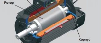
Somewhat less common among DC motors are brushless design models (BrushLess DC or BLDC), which use a rotor with permanent magnets that rotate between stator electromagnets (Figure 4). Current switching here is performed electronically. Switching the windings of the stator electromagnets causes the rotor's magnetic field to follow its field.
Rice. 4. Operating principle of brushless DC motor (BLDC)
The current rotor position is usually monitored by encoders or a Hall effect sensor, or technology is used to measure the back-EMF voltage on the windings without using a separate rotor position sensor (SensorLess) in this case.
Current switching of the stator windings is performed using electronic switches (valves). This is why brushless BLDC motors are often called "valve-type" motors. The order of connection of a pair of motor windings depends on the current position of the rotor.
The operating principle of BLDC is based on the fact that the controller switches the stator windings so that the stator magnetic field vector is always shifted by an angle close to 90° or -90° relative to the rotor magnetic field vector. The magnetic field rotating during switching causes the rotor with permanent magnets to move after it.
When using a three-phase control signal, only two pairs of windings are always connected to the current source, and one is disconnected. As a result, a combination of six states is used sequentially (Figure 5).
Rice. 5. Phase rotation when rotating BLDC
Electric motors without rotor position sensors are characterized by increased manufacturability of the manufacturing process and lower cost. This design simplifies the sealing of external connected terminals.
Hall sensors can be used as rotor speed and position sensors in BLDC, which are low cost, but also have a fairly low resolution. Increased resolution is provided by rotating transformers (resolvers). They are expensive and require the use of a DAC, since their output signal is sinusoidal. Optical sensors have high resolution, but reduced reliability. Figure 6 shows the output signals of different types of sensors when the engine rotor rotates.
Rice. 6. Rotor position sensors for electric motors
L298N motor driver program
Let's write a simple program that will rotate the motor in one direction for 3 seconds at maximum speed, and then 3 seconds in the opposite direction at a slower speed.
byte ena = 3; byte in1 = 4; byte in2 = 5; void setup() { pinMode( ena, OUTPUT ); pinMode( in1, OUTPUT ); pinMode( in2, OUTPUT ); } void loop() { // set 100% power on motor A - 255 out of 255 analogWrite( ena, 255 ); // set the motor mode - clockwise rotation digitalWrite( in1, HIGH ); digitalWrite(in2, LOW); delay(3000); // pause 3 seconds // set the power to motor A - 150 out of 255 analogWrite( ena, 150 ); // motor mode - counterclockwise rotation digitalWrite( in1, LOW ); digitalWrite(in2, HIGH); delay(3000); // pause 3sec }
We load the program onto the Arduino, then connect the batteries to the driver and see how the motor behaves.
It should be noted that this program does not guarantee that the motor will rotate at any specific speed. We can only change the power transmitted to the motor by changing the duty cycle of the PWM signal. You can learn more about the PWM signal in one of our lessons.
Stepper motors
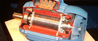
Stepper motors (SM) have become quite widespread in automation and control systems. They are another type of brushless DC motor. Structurally, motors consist of a stator on which the field windings are located, and a rotor made of magnetic materials. Stepper motors with a magnetic rotor make it possible to provide greater torque and rigid fixation of the rotor when the windings are de-energized.
During rotation, the motor rotor moves in steps under the control of power pulses supplied to the stator windings. Stepper motors are convenient for use in drives of machines and mechanisms operating in start-stop mode. Their range of movement is set by a specific sequence of electrical impulses. Such motors are highly accurate and do not require sensors or feedback circuits. The angle of rotation of the rotor depends on the number of control pulses supplied. The positioning accuracy (step size) depends on the design features of the motor, the connection diagram of the windings and the sequence of control pulses supplied to them.
Depending on the configuration of the winding connection diagram, stepper motors are divided into bipolar and unipolar. A bipolar motor has in each of the two phases a single winding for both poles of the stator, which must be reversed by the driver to change the direction of the magnetic field. A bipolar motor has two windings and, accordingly, four outputs. To control such a stepper motor, a bridge driver or half-bridge circuit with 2-polar power supply is required. With bipolar control, two windings operate simultaneously and the torque is approximately 40% greater. Figure 7 shows the sequence of control signals during rotation of the bipolar motor.
Rice. 7. Sequence of bipolar stepper motor control signals
A unipolar motor uses one winding in each phase with a middle terminal and allows the use of a simpler control circuit with one switch for each of the four half-windings.
Four-winding motors can be used in both bipolar and unipolar configurations.
When current flows through one of the coils, the rotor tends to change position so that the opposite poles of the rotor and stator are positioned opposite each other. To ensure continuous rotation of the rotor, the coils are switched alternately.
In practice, different methods are used to supply power to the four stator windings. Most often, paired connections with full-step or half-step operating modes are used. In full-step mode, a rotor with two poles, rotating in the switchable magnetic field of two pairs of coils, can occupy four positions (Figure 8).
Rice. 8. Full-step motor control mode
The half-step operating mode allows you to obtain double positioning accuracy and eight positions (Figure 9). To implement it, an intermediate step is added with simultaneous powering of all four coils.
Rice. 9. Half-step motor control mode
The microstepping mode allows you to significantly increase the number of intermediate positions and positioning accuracy. The idea of a microstep is to supply a continuous signal resembling a stepped sine wave in shape to the windings of a stepper motor instead of control pulses (Figure 10). In this case, the full step is divided into small microsteps, and the rotation becomes smoother. Microstepping mode allows you to get the most accurate positioning. In addition, in this mode, the vibration of the housing inherent in stepper motors is significantly reduced.
Rice. 10. Motor control in microstep mode
Example sketch for control
In the set of examples of the Stepper.h library, there is a program stepper_oneRevolution, in which all parameters for the stepper motor are set - the number of steps, speed, rotation.
#include const int stepsPerRevolution = 200; Stepper myStepper(stepsPerRevolution, 8,9,10,11); //connect to pins 8...11 on Arduino void setup() { myStepper.setSpeed(60); //setting the rotor rotation speed Serial.begin(9600); } void loop() { //The function waits for a command to arrive, converts the text and sends a signal to the motor to rotate it the specified number of steps. Serial.println("Move right"); //clockwise myStepper.step(stepsPerRevolution); delay(1000); Serial.println("Move left"); //counterclockwise myStepper.step(-stepsPerRevolution); delay(1000); }
Traditional solutions for electric motor control
A modern precision DC motor control system includes a microcontroller for data processing and a motor control unit, often called a driver. The driver includes a logic circuit for converting encoded messages into digital control signals, from which analog signals are generated in the Gate Driver block to control power switches based on field-effect transistors (FETs). FETs can be part of the driver or placed in a separate block. In addition, the driver includes power circuit protection circuits and feedback circuits to control engine operation.
Figure 11 shows the block diagram options for the integrated and pre-drivers. Each of the solutions has its own advantages and features. The Pre-Driver has a significantly improved temperature regime and allows you to select external power switches in accordance with the power of the connected engine. A full-featured integrated driver allows you to create more compact control systems, minimizes external connections, but makes it much more difficult to ensure the required temperature conditions.
Rice. 11. Block diagrams of engine control systems
Thus, for the integrated driver TI DRV8312, the maximum operating temperature of individual elements on the board can reach 193°C, while for the preliminary driver DRV8301 this figure does not exceed 37°C.
Rice. 12. Changing the direction of rotation of the commutator motor
One of the most common circuits for switching motor windings is the “H” bridge. The name of the circuit refers to the connection configuration, which looks like the letter “H”. This electronic circuit allows you to easily change the direction of current in the load and, accordingly, the direction of rotation of the rotor. The voltage applied to the windings through the bridge transistors can be either constant or modulated using PWM. The H-bridge is designed, first of all, to change the polarity of the motor power supply - reverse (Figure 12), but also allows you to slow down the rotation by short-circuiting the terminals of the windings (Figure 13).
Rice. 13. Rotation, fast and slow braking modes
The most important characteristic of the power elements of the bridge, which today are often used as field-effect transistors with an insulated gate, is the resistance value of the open channel between the source and drain of the transistor - RDSON. The RDSON value largely determines the thermal characteristics of the unit and energy losses. As the temperature increases, RDSON also increases, and the current and voltage on the windings decrease.
The use of PWM control signals can reduce torque ripple and ensure smoother rotation of the motor rotor. Ideally, the PWM frequency should be higher than 20 kHz to avoid acoustic noise. But as the frequency increases, the losses on the bridge transistors during the switching process increase.
Due to the inductive properties of the load in the form of windings, the shape of the current in it does not correspond to the shape of the applied PWM voltage. After applying a voltage pulse, the current increases gradually, and during pauses the current gradually fades due to the occurrence of back-EMF in the windings. The slope of the current curve, amplitude and frequency of the pulsations affect the performance characteristics of the motor (torque ripple, noise, power, etc.).
To accelerate the attenuation in the windings of electric motors of the current excited by the back-EMF effect, diodes are used in reverse connection, shunting the drain-source transitions of transistors, or the windings are short-circuited through the drain-source transitions of two transistors simultaneously connected in different arms of the bridge. Figure 13 shows three states of the bridge: working, fast braking (Fast Decay) and slow braking (Slow Decay).
And the most effective is considered to be the combined mode (Mixed Decay), in which, during the pause between operating pulses, the diodes that shunt the drain-source of the transistors first operate, and then the transistors in the lower arms of the bridge turn on.
Connecting L298N to Arduino
As already mentioned, first of all you need to check the polarity of the connected motors. Motors that rotate in different directions are difficult to program.
You need to connect a power source. + connects to pin 4 on the L298N board, minus (GND) – to pin 5. Then you need to connect the outputs from the L298N and the pins on the Arduino, some of which must support PWM modulation. On the Arduino board they are marked ~. Connect the outputs from L298N IN1, IN2, IN3 and IN4 to D7, D6, D5 and D4 on the Arduino, respectively. The connection of all other contacts is shown in the diagram.
The direction of rotation is specified using the HIGH and LOW signals on each channel. The motors will start rotating only when there is a HIGH signal on pin 7 for the first motor and pin 12 for the second on the L298N. Feed LOW stops rotation. To control the speed, PWM signals are used.
To control a stepper motor in the Arduino IDE, there is a standard Stepper library. To check the functionality of the assembled circuit, you can download the test example stepper_oneRevolution. When assembled correctly, the motor shaft will begin to rotate.
When working with motors, Arduino may periodically reboot. This occurs due to the fact that motors require large currents at start and during braking. To solve this problem, capacitors, diodes and other circuits are built into the board. Also for these purposes, the shidla has separate power supply.
TI Motor Control Solutions
TI's semiconductor components include a wide range of different drivers for controlling DC motors. All of them require a minimum of external components, allow you to create compact solutions for controlling motors with operating voltages up to 60 V, are characterized by increased reliability, and provide quick and simple design of electric motor drive systems.
Intelligent features built into the drivers require minimal external microcontroller (MCU) support, provide advanced winding switching capabilities, and support external sensors and digital control loops. The set of protective functions includes limiting the supply voltage, protection against overcurrent and short circuit, undervoltage and increased operating temperature.
The entire range of TI drivers is divided into three sections: stepper, brushed and brushless DC motors. In each of them, the company’s website has a convenient selection system based on a number of parameters. There are separate drivers designed for use with different types of engines.
Current setting A4988
Before using the driver, we need to do a little configuration. We need to limit the maximum current flowing through the stepper motor coils and prevent the motor from exceeding the rated current.
There is a small potentiometer on the A4988 driver that can be used to set the current limit. You must set the current limit equal to or lower than the rated current of the motor.
There are two methods to adjust the stepper motor current:
Method 1:
In this case, we are going to set the current limit by measuring the voltage (Vref) at the "ref" pin.
- Take a look at the data sheet for your stepper motor. Write down its current rating. In our case we are using NEMA 17,200 steps/rev, 12V 350mA.
- Place the driver in full-step mode, leaving the three microstep select pins disabled.
- Keep the motor in a fixed position without synchronizing the STEP input.
- During adjustment, measure the voltage Vref (one multimeter probe to the minus power supply, and the other to the metal body of the potentiometer).
- Adjust the voltage Vref using the formula:
current limit = Vref x 2.5
For example, if your motor is rated at 350mA, you would set the reference voltage to 0.14V.
Method 2:
In this case, we are going to set the current limit by measuring the current flowing through the motor coil.
- Take a look at the data sheet for your stepper motor. Write down its current rating. In our case we are using NEMA 17,200 steps/rev, 12V 350mA.
- Place the driver in full-step mode, leaving the three microstep select pins disabled.
- Keep the motor in a fixed position without synchronizing the STEP input. Don't leave the STEP input hanging in the air, connect it to a logic power supply (5V)
- Connect an ammeter in series with one of the stepper motor coils and measure the actual current.
- Take a small screwdriver and adjust the current limit potentiometer until you set the stepper motor's current rating.
TI Drivers for Stepper Motors
TI's large portfolio of motor control solutions includes motor drivers (Figure 14), which are available both with built-in FET-based power switches and as pre-drivers that provide the user with the selection of necessary power switches. In total, the company’s model range includes more than 35 drivers for SD.
Rice. 14. TI drivers for controlling stepper motors
TI offers a wide range of state-of-the-art motion control and precision positioning solutions using microstepping control circuits that enable motors to move smoothly over a wide range of voltages and currents.
Separate drivers, using one control controller, allow you to control two motors at once, having for this purpose four built-in bridges based on FET. There are drivers with built-in FETs, such as the DRV8834, which can be connected to drive two stepper motor windings or use the same pins to drive two DC motors (Figure 15).
Rice. 15. DRV8834 driver block diagram
To move the rotor more smoothly, drivers for stepper motors use a customizable mechanism for smoothing current pulses (Slow, Fast, Mixed Decay modes). The microstep calculation system can be of the following types:
- built into the driver;
- using an external reference signal.
The DRV881, DRV8818, DRV8821, DRV8824 and DRV8825 drivers do not require an external controller for microstepping . Here, the movement step and the winding switching algorithm are calculated by a circuit built into the driver.
The simpler drivers DRV8812, DRV8813, DRV8828, DRV8829, DRV8841, DRV8842 and DRV8843 provide micro-stepping rotation using an external reference voltage (Vref) controller. The main step crushing level can reach 1/128 or 1/256.
To control step motors with unipolar winding connections, TI offers drivers DRV8803, DRV8804, DRV8805 and DRV8806 .
L293D motor driver
L293D is the simplest microcircuit for working with engines. The L293D has two H-bridges that allow you to control two motors. The operating voltage of the microcircuit is 36 V, the operating current reaches 600 mA. The L293D motor can supply a maximum current of 1.2A.
The circuit has 16 outputs. Pinout:
- +V – 5 V power supply;
- +Vmotor – supply voltage for motors up to 36 V;
- 0V – ground;
- En1, En2 – turn H-bridges on and off;
- In1, In2 – control the first H-bridge;
- Out1, Out2 – connection of the first H-bridge;
- In3, In4 – control the second H-bridge;
- Out3, Out4 – connection of the second H-bridge.
To connect to the Arduino Uno microcontroller, you need to connect outputs In1 on L293D and 7 pins on Arduino, In2 – 8, In3 – 2, In4 – 3, En1 – 6, En2 – 5, V – 5V, Vmotor – 5 V, 0V – GND . An example of connecting one motor to Arduino is shown in the figure.
TI Drivers for BDC
To control brushed DC motors, a special family of drivers DRV8x , a number of representatives of which are shown in Figure 16. They provide complete protection against overvoltage and current, short circuit and overheating. Thanks to the control interface capabilities, these drivers enable simple and efficient operation of motors. Users can control one or more motors with an operating voltage of 1.8...60 V using a single chip.
Rice. 16. TI drivers for controlling brushed motors
The drivers of the family are available both with integrated power switches and as pre-drivers. They require a minimum of additional components, provide compact solutions, reduce development time and allow you to quickly release new products to the market.
Sleep mode minimizes power consumption when idle and provides faster activation when the engine starts. To control the rotation speed, external PWM signals or PHASE/ENABLE signals can be used to select the direction of rotation and turn on the output bridge switches.
Having four output bridges, the DRV8823 is capable of controlling two motors, or one motor and two BDCs, or four BDCs, using the SPI control interface.
Figure 17 shows the functional diagram of a simple DRV8837 for controlling a single brushed motor.
Rice. 17. DRV8837 driver block diagram
Motor driver on HG7881 chip
HG7881 is a two-channel driver that can connect 2 motors or a four-wire two-phase stepper motor. The device is often used due to its low cost. The driver is used only to change the direction of rotation; it cannot change the speed.
The board contains 2 L9110S circuits that work as an H-bridge.
HG7881 driver specifications:
- 4-pin connection;
- Power supply for motors from 2.5 V to 12 V;
- Current consumption less than 800 mA;
- Small dimensions, light weight.
Pinout:
- GND – ground;
- Vcc – supply voltage 2.5V – 12V;
- A-IA – input A(IA) for motor A;
- A-IB – input B (IB) for motor A;
- B-IA – input A(IA) for motor B;
- B-IB – input B (IB) for motor B.
Depending on the signal applied, outputs IA and IB will have different states for the motors. Possible options for one of the motors are shown in the table.
| I.A. | I.B. | Motor condition |
| 0 | 0 | Stop |
| 1 | 0 | Moving forward |
| 0 | 1 | Moves backwards |
| 1 | 1 | Shutdown |
Connecting one motor to Arduino is shown in the figure.
Comparison of modules
The L293D module supplies a maximum current of 1.2A, while the L298N can achieve a maximum current of 4A. The L293D also has lower efficiency and heats up quickly during operation. At the same time, L293D is the most common board and is inexpensive. The HG7881 board differs from the L293D and L298N in that it can only be used to control the direction of rotation; it cannot change the speed. HG7881 is the cheapest and smallest module.
TI Drivers for BLDC
TI's brushless motor drivers, or BLDCs, can include an integrated power bridge or use external power transistors. The circuit for generating 3-phase control signals can also be external or built-in.
The family of drivers for controlling brushless electric motors includes models with different control principles and with different torques. These drivers, which provide different noise levels when driving BDLC, are ideal for use in industrial equipment, automotive systems and other equipment. To ensure reliable motor operation, the drivers provide a comprehensive set of overcurrent, overvoltage and overtemperature protections. Figure 18 shows just a few of the 3-phase BLDC drivers in TI's extensive and growing product line.
Rice. 18. TI drivers for controlling brushless motors
To monitor the current position of the rotating rotor, external sensors of various types or a control circuit can be used to determine the rotor position by the value of the back EMF (Back Electromotive Force, BEMF).
Control can be performed using PWM, analog signals or via standard digital interfaces. Sets of configurable parameters for rotation control can be stored in internal non-volatile memory.
Figure 19 shows an intelligent driver for BLDC operating in a wide temperature range of 40...125°C with built-in power switches on field-effect transistors, with an open channel resistance of only 250 mOhm. With an operating voltage range of 8...28 V, the driver can provide a nominal current of 2 A and a peak current of 3 A.
Rice. 19. DRV10983 driver block diagram
The driver does not require an external sensor to monitor the rotor position, but can use an external resistor to monitor the power consumed by the motor. The DRV10983 features low power consumption of only 3 mA in standby mode. And in the DRV10983Z this figure is increased to the level of 180 μA.
The built-in I2C interface provides diagnostics and configuration, access to logic circuit operation control registers and driver operating profiles stored in EEPROM memory.
An advanced set of protective functions ensures that the motor stops in case of overcurrent and undervoltage. Input voltage limitation is provided. Overcurrent protection works without the use of an external resistor. Methods for using protection are configured through special registers.
Smoothing device TL-Smoother
A board that connects the stepper driver and stepper motor, reducing noise and vibration in your 3D printer, reducing the risk of zebra stripe defects.
This small board has eight rectifier diodes that improve the stepper motor waveform, particularly for older, cheaper stepper drivers such as the DRV8825 and A4988. Improving the waveform reduces engine noise by reducing vibration. Since vibrations are reduced, print quality also improves. Just install the board between the driver and the stepper motor, the orientation doesn't matter. For convenience, the kit includes a small 4-wire connector, 20 cm long, to connect the board to the electronics. Cost about 7 $
Zebra stripe or moire defect
How TL-Smoother works
TL-Smoother circuit
The origins of TL smoothing technology back to 2015 when user Schrodinger Z blogged about the jerky movements of the stepper motor and investigated what was happening. As it turns out, the DRV8825 stepper drivers he was using did not generate smooth sine waves for the motors. Upon further inspection, it was discovered that the drivers could not output signals properly at low currents because they were in what is known as a “dead zone.”
The TLs were created to address a specific design flaw in the DRV8825 drivers.