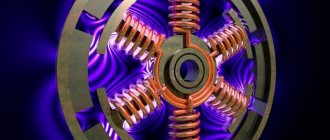
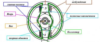
Stepper motors do not have commutators or brushes. These are synchronous DC motors with an electronically commutated magnetic field that causes rotation of the armature (its magnets). Stepper motors can be considered to be controlled by digital pulses, and in a stepper motor, the full angle of rotation of the rotor is divided into a discrete number of steps. The number of these stages (phases) is equal to the number of magnets located around the central core.
Stepper motor design
Theory of operation of stepper motors. Unlike DC or AC motors, stepper motors require a serial supply, meaning they must receive a fixed sequence of pulses to individual coils. There are also bipolar and unipolar motors. A unipolar stepper motor differs from a bipolar one in that it has an additional winding tap, which divides the winding into two parts. Typically, a bipolar stepper motor has 4 or 8 pins, while a unipolar stepper motor has 5 or 6 pins.
How to spin a stepper motor
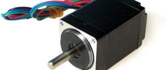
A stepper motor works by applying voltage combinations in different directions to its windings, this stepper motor has 2 windings - 4 wires, the first winding is black (A) and green (A*) wire, the second winding is red (B) and blue (B *).
During one change of combinations, 1 step is taken - 1.8 degrees. If the combinations are quickly changed, the engine will quickly and accurately position itself - spin. Changing combinations is possible in two directions; accordingly, the engine will spin forward or backward. To rotate a stepper motor, you need to:
1) Assemble a device - a USB stepper motor controller on an AVR microcontroller and a stepper motor driver, 2 in 1. Before assembling this complex device, I recommend first separately assembling and testing the operation of only the USB controller, I have already assembled it here - USB controller. If the USB connection works normally, then you can start making the driver.
2) Write a program for a computer that will send USB commands to the device.
3) Write a program for the AVR microcontroller that will accept USB commands and turn the engine.
Required Components
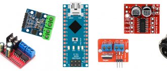
- Microcontroller ATmega16 (buy on AliExpress).
- Programmer AVR-ISP (buy on AliExpress), USBASP (buy on AliExpress) or another similar one.
- 16 MHz crystal oscillator (buy on AliExpress).
- Stepper motor 28BYJ-48 (buy on AliExpress).
- Motor driver ULN2003 (buy on AliExpress) or L293D (buy on AliExpress).
- Capacitor 100 nF (2 pcs.) (buy on AliExpress).
- Capacitor 22 pF (2 pcs.) (buy on AliExpress).
- Button.
- LED (buy on AliExpress).
- Bread board.
- Connecting wires.
- Power supply with a voltage of 5 Volts.
USB stepper motor controller and USB stepper motor driver
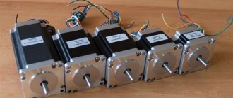
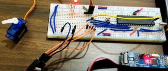
The engine we took is a hybrid and supports several control options. We will control the motor using the bipolar method and accordingly we will assemble a bipolar stepper motor driver with a USB controller. First I’ll show you the finished result, and then we’ll look at it in detail. Here is a photo of the assembled USB controlled stepper motor driver that I assembled:
DIY stepper motor driver with USB control |
The picture above shows a bipolar (hybrid) NEMA 23 stepper motor with a current consumption of 3A per winding.
Below it is a switching power supply 360 W, 24 V, 15 A. The power of the unit is enough for 15 / 3 = 5 simultaneously powered windings, one motor has 2 windings, that is, enough for 2 simultaneously operating motors (4 windings). I don’t see the need to turn on more than one engine at a time; if it is necessary to move along a curved trajectory, then you need to alternate short turns on first one or the other engine. So the available power is sufficient with a reserve. The motor and power supply are connected to the device, which is also connected via USB to the computer. Everything is connected according to the diagram. Bipolar stepper motor driver and USB controller circuit (the circuit is long and needs to be scrolled to view):
DIY USB stepper motor driver on AVR microcontroller |
Electronic components that need to be purchased to assemble the device according to the scheme:
ATmega16A
| 160 RUB. | PC. | BUY |
What is this:
Microcontroller
Control:
40 lines
Program memory:
16 Kb
Driver IR2101
| 50 RUB. | PC. | BUY |
What is this:
Key driver
Keys:
2 transistors
Frame:
DIP-8
Transistor IRF540N
| 35 RUB. | PC. | BUY |
What is this:
Key
Maximum current:
33 A
Max. voltage:
100 V
Zener diode 3V6
| 2 RUB. | PC. | BUY |
Skips:
3.6 V
Type:
Downward
Diode 1n4148
| 2 RUB. | PC. | BUY |
Type:
Ordinary
Maximum current:
0.15 A
Max. voltage:
100 V
Capacitor 20 pF
| 4 RUB. | PC. | BUY |
Capacity:
20 pF
Type:
Ceramic
Max. voltage:
50 V
Capacitor 3.3 nF
| 4 RUB. | PC. | BUY |
Capacity:
3.3 nF
Type:
Ceramic
Max. voltage:
50 V
Crystal oscillator 12
| 5 RUB. | PC. | BUY |
Frequency:
12 MHz
Type:
passive
Capacitor 2A104J
| 5 RUB. | PC. | BUY |
Type:
Film
Capacity:
0.1 uF (µF)
Max. voltage:
100V
Terminal block
| 15 RUB. | PC. | BUY |
Contacts:
2
Clamp:
screwing
68 ohm resistor
| 1 RUB. | PC. | BUY |
Resistance:
68 Ohm
Power:
0.25 W
Resistor 1.5 kOhm
| 1 RUB. | PC. | BUY |
Resistance:
1.5 kOhm
Power:
0.25 W
100 ohm resistor
| 1 RUB. | PC. | BUY |
Resistance:
100 Ohm
Power:
0.25 W
10 ohm resistor
| 1 RUB. | PC. | BUY |
Resistance:
10 ohm
Power:
0.25 W
Resistor 0.1 Ohm
| 15 RUB. | PC. | BUY |
Resistance:
0.1 Ohm
Power:
5 W
Type:
Cement
USB cable
| 50 RUB. | OUT OF STOCK Need 1 piece. |
Interface:
USB 2.0
Length:
100 cm
Bread board
| 190 RUB. | PC. | BUY |
Size:
63 x 2 horizontal lines and 4 vertical lines
Postings
| 80 RUB. | PC. | BUY |
Type:
Mounted
Quantity:
40
Set of wiring
| 210 RUB. | PC. | BUY |
Quantity:
140
Additionally needed (out of stock):
1) DC-DC power module SMAU01L-12 (any DC-DC converter from 5V to 10V-15V will do instead) - 1 pc., perhaps you can without it, power from 5V (not verified)
The main component of the circuit is the programmable microcontroller AVR - ATmega16A, if you do not know how to work with them (write a program), first familiarize yourself with the basics of such work, which are described in detail in the first article, machine control. You can use another AVR microcontroller for the device; I chose ATmega16A, because it has plenty of memory and contacts to connect several motors and a large number of working tools.
To the left of the ATmega16A there are components for organizing communication via the USB protocol - an external quartz resonator with a USB-compatible frequency of 12 MHz is connected to the XTAL pins. To smooth the signal, it has 2 20 pF capacitors, all of which are connected to the power supply negative. The contacts through which messages are exchanged with USB are connected to 2 68 Ohm resistors, as required by the USB protocol. A 1.5 kOhm resistor connected to the D-line sets the low-speed operating mode of the USB device. 3V6 Zener diodes lower the voltage on the lines through which USB data is exchanged from 5 to 3.6V.
The motor control is connected to contacts PB0, PB1, PB2, PB3; the remaining free P-contacts can be used to connect more motors and working tools in the future, but for now they are empty. The ATmega16 microcontroller issues commands and processes USB signals after a program is written into it (it will be written below). After it comes a design made of IR2102 microcircuits and IRF540N transistors (2 so-called H-bridges) - it drives the stepper motor.
The IR2101 driver is needed to overcome the high gate capacitance of the IRF540N transistor, which allows you to open and close the transistor at high speed (for example, receive a PWM signal, which can regulate the motor speed if necessary - I will write about this signal later), which is what we need. Unfortunately, this driver requires 10-15V to power it, we only have 5V from USB. Therefore, I had to install the DC-DC component SMAU01L-12, which converts 5V to 12V; instead, you can use any other method of obtaining such voltage, for example, using a transformer or any other way. +12V is connected to VCC, -12V to COM. One driver works with 2 transistors - upper (H) and lower (L). Contacts HIN and LIN are an input signal from the microcontroller for the upper and lower transistors; according to this signal, the transistors open and close. HO and LO are output signals, transistors are connected by gates (G) to these contacts. They are connected for a reason - on the right side of the lines there are 2 10/100 Ohm resistors and a diode, they are needed for the normal operation of the transistors - so that they slow down when opening and do not slow down when closing, these transistors open too quickly and this can cause problems. A diode and capacitors of 3300 pF are needed for the operation of the IR2101 driver according to the documentation for this chip.
Each winding (phase) of the motor (the motor has 2 windings A and B - 4 contacts) is connected to an H-bridge made of IRF540N transistors. An H-bridge is a special circuit for connecting transistors, which allows high-level voltage (24V) to be supplied through them in different directions. One bridge is made of 4 transistors. As a result, here you see 2 H-bridges, which allow you to drive multidirectional high-level voltage across 2 motor windings and thereby turn it.
Please note that in a bridge, the HIN of the upper driver is connected to the LIN of the lower driver, and the LIN of the upper is connected to the HIN of the lower one. This is done to provide simultaneous signals. If you turn on HIN from the top, you must turn on LIN from the bottom, otherwise a short circuit will occur. This connection allows you to automatically turn on the pair. However, a short circuit is still possible if you open both HIN and LIN on the same bridge, so do not allow this to happen. On contacts PB0 - PB3, only values 0000, 1010, 0110, 0101, 1001 are allowed. Selecting them turns the engine over. Providing other values will most likely result in a short circuit in the bridge.
Powerful resistors with a low value of 0.1 Ohm and high power (3-5 W) are needed to protect against high current - these are shunts. If anything, they can be removed and replaced with a simple connection with a minus power supply, if, for example, there is not enough power. For weak resistors, the power is taken from the USB current: 0.05 A * 5 V = 0.25 W (USB current is set by software, by default in our program it is 0.05). The black stripe on the diodes corresponds to the vertical line in the diagram.
The stepper motor and power supply are connected to the H-bridges as shown in the diagram. Cons of 24V, 12V and 5V power supply are connected. A smoothing film capacitor is placed between the plus and minus of the 24V line.
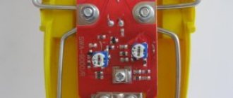
Separate large photo of the stepper motor driver:
DIY stepper motor driver |
I do not recommend immediately connecting high-level power (24V) to the circuit and the stepper motor.
First, it is better to check that the device is working correctly. To do this, you can use 5 LEDs and the battery compartment as a power source (3V). 1 LED is connected to pin PA0 with the long side (+) and the short side (-) to the power supply minus. This yellow diode is shown in the first photo above, it is not on the diagram. With its help, you can check the operation of the USB controller, turn it on and off by command from the program. Connect 2 other LEDs to the place of the first winding of the stepper motor in opposite directions - one with the long side to the first contact, the other long side to the second contact. Connect the remaining 2 LEDs in the same way in place of the second winding. Instead of a 24V switching power supply, connect the battery compartment and 1.5V batteries (2 batteries are 3V). Device check - When a command is sent to turn the motor, various LEDs light up. All LEDs should light up at the right time when going through combinations. Slowly going through the combinations allows you to make sure that everything works correctly. Light-emitting diode
| 3 RUB. | PC. | BUY |
Color:
White
Voltage:
3V
Battery compartment
| 35 RUB. | PC. | BUY |
Places:
2 with wiring
Battery size:
A.A.
Batteries
| 10 RUB. | OUT OF STOCK Need 2 pcs. |
Voltage:
1.5V
Size:
A.A.
Circuit operation
The following two tables show the connection diagrams of the input and output contacts of the ULN2003 or L293D motor drivers with the AVR ATmega16 microcontroller and stepper motor.
| Atmega16 | ULN2003 | L293D |
| A0 | IN1(PIN1) | IN1(PIN2) |
| A1 | IN2(PIN2) | IN2(PIN7) |
| A2 | IN3(PIN3) | IN3(PIN10) |
| A3 | IN4(PIN4) | IN4(PIN15) |
| Stepper motor | ULN2003 | L293D |
| Orange | OUT1(PIN16) | OUT1(PIN3) |
| Yellow | OUT2(PIN15) | OUT2(PIN6) |
| Pink | OUT3(PIN14) | OUT3(PIN11) |
| Blue | OUT4(PIN13) | OUT4(PIN14) |
The diagram of the device with the ULN2003 motor driver is shown in the following figure.
The diagram of the same design, but with an L293D motor driver, will look like this.
The appearance of the device using ULN2003 is shown at the beginning of the article, and using L293D it will look like this:
Connect all components of the device in accordance with the connection diagram shown (one of two). To control the stepper motor we will use PORTA of the Atmega16 microcontroller. There is no need to connect power to the stepper motor contacts - to control it we only need the contacts of its coils (coil pins) - this is true for ULN2003, for L293D it is a little different. The order of the contacts is very important for the stepper motor to work correctly. The ULN2003 chip uses four of its inputs and four of its outputs - the inputs are connected to the PORTA pins of the microcontroller, and the outputs are connected to the signal pins of the stepper motor. Also connect the button to the reset pin to be able to reset the Atmega16 microcontroller whenever we need it. Connect a crystal oscillator to the microcontroller. The entire device must be powered with a voltage of 5V.
Windows program for engine
A ready-made program for Windows for a USB controller needs to be slightly modified. As a result, combinations for supplying voltage in different directions must be sorted out, we need to change the values on ports PB0, PB1, PB2, PB3, the following combinations are needed to start the engine 1010, 0110, 0101, 1001. Trying them in one direction - torsion in this direction , in the other - reverse torsion. 0000 - turns off the power, necessary at the end of the search, otherwise the engine will heat up. Now we are working on this program, so take it from the USB controller, the connection works there, by analogy you can do the rest as needed at home.
Key input module
KEY0 on the STM32F4 development board is connected to PE4, KEY1 is connected to PE3, KEY2 is connected to PE2, and KEY_UP is connected to PA0. As shown:
In this experiment, we set to press KEY-UP, the motor will return to the absolute origin at the given frequency; press KEY0, the motor will rotate clockwise at the set frequency; press Press KEY1, the motor rotates counterclockwise at the set frequency. Here are the general steps to implement key input: ① The power button corresponds to the clock of the I/O port. Call function: RCC_AHB1PeriphClockCmd(); ② Initialize I/O mode: input up/down. Call function: GPIO_Init(); ③ I/O port level scan (library function/register/bit operation). The corresponding code looks like this:
void KEY_Init(void) { GPIO_InitTypeDef GPIO_InitStructure; RCC_AHB1PeriphClockCmd(RCC_AHB1Periph_GPIOA|RCC_AHB1Periph_GPIOE, ENABLE);// Enable GPIOA, GPIOE clock GPIO_InitStructure.GPIO_Pin = GPIO_Pin_2|GPIO_Pin_3|GPIO_Pin_4; // KEY0 KEY1 KEY2 corresponding pin GPIO_InitStructure.GPIO_Mode = GPIO_Mode_IN;// Normal input mode GPIO_InitStructure.GPIO_Speed = GPIO_Speed_100MHz;//100M GPIO_InitStructure.GPIO_PuPd = GPIO_PuPd_UP;// pull up GPIO_Init(GPI OE, &GPIO_InitStructure);//Initializing GPIO2, 3, 4 GPIO_InitStructure.GPIO_Pin = GPIO_Pin_0;// WK_UP corresponding pin GPIO_InitStructure.GPIO_PuPd = GPIO_PuPd_DOWN; // dropdown GPIO_Init(GPIOA, &GPIO_InitStructure);// Initializing GPIOA0 } u8 KEY_Scan(u8 mode) { static u8 key_up=1;// release button if(mode)key_up=1; // Connection support if(key_up&&(KEY0==0||KEY1==0||KEY2==0||WK_UP==1)) { delay_ms(10);//Debad key_up=0; if(KEY0==0)return 1; else if(KEY1==0)return 2; else if(KEY2==0)return 3; else if(WK_UP==1)return 4; }else if(KEY0==1&&KEY1==1&&KEY2==1&&WK_UP==0)key_up=1; return 0;//no key pressed }
Cooling system - radiator
Excessive power dissipation of the A4988 driver IC results in elevated temperatures that may exceed the IC's capabilities, likely resulting in damage to the IC.
Even though the A4988 driver IC has a maximum current rating of 2A per coil, the IC can only supply about 1A per coil without overheating.
To achieve more than 1A per coil, a heatsink or other cooling method is required.
The A4988 driver usually comes with a heatsink. It is advisable to install it before using the driver.