What affects the characteristics of the power supply network?
The quality of electricity depends on a huge number of factors that change the indicators beyond the limits established by regulations. Thus, the voltage may be too high due to an accident at the substation. Low values appear in the evening or in the summer season, when people return home and turn on televisions, electric stoves, and split systems.
The quality of electricity according to GOSTs may vary slightly. In very poor supply networks, consumers have to use voltage stabilizers. Control over the characteristics is entrusted to Rospotrebnadzor, which can be contacted if inconsistencies arise.
Power quality may depend on the following factors:
- Daily fluctuations associated with uneven connection by consumers or with the influence of tides at sea stations.
- Changes in the air environment: humidity, ice formation on power wires.
- Changes in the wind when power is generated by wind turbines.
- The quality of the wiring will wear out over time.
Why are the main characteristics of the power supply network needed?
The quantitative value and deviation errors of parameters are established in accordance with GOST. The quality of electricity is specified in document 32144-2013. It was necessary to legalize these indicators due to the risk of fire in consumer devices, as well as disruption of the functioning of electrical appliances in installations sensitive to voltage drops. The latest devices are common in medical institutions, research centers, and military facilities.
Power quality indicators were updated in 2013 due to the development of the energy market and the emergence of new electronic devices. Electricity, as part of its supply, should be considered as a product that meets certain criteria. If the established characteristics are deviated, administrative liability may be applied to providers. If, due to fluctuations in incoming voltage, people were or could be injured, then criminal liability may arise.
The main causes of voltage deviations in the network
Now let's look at what could cause a change in network characteristics:
- Steady voltage deviations are associated with the following reasons:
- An increase in the load due to the connection of one or more powerful consumers. A typical example is the seasonal increase in load on energy systems due to the connection of heating equipment, as well as daily peaks.
- Increasing the number of consumers without modernizing the energy system.
- Break or insufficient contact quality of the neutral cable in three-phase systems.
In the situations described in the first paragraph, the supplier normalizes the voltage using special means of regulation. In other cases, repair work is carried out.
- The cause of voltage drops is associated with consumers of electrical energy, with a sharply changing load (as a rule, the reactive power also changes). An example is metallurgical enterprises equipped with arc furnaces. A similar effect can be observed during the operation of welding electrical equipment or piston compressor units.
- The causes of minimum voltage (dips) in most cases are associated with short circuits that can occur in the home network, on input lines or power lines. The duration of dips varies from milliseconds to seconds, and the voltage can decrease to 90% of normal. Electronics are the most sensitive to such changes; their operation can be normalized using a UPS.
- The occurrence of pulse voltages can be caused by switching processes, a lightning strike in an overhead line, as well as other reasons. In this case, the magnitude of the pulse can be many times higher than the standard voltage in the apartment according to GOST. Naturally, a significant increase in the maximum values of this parameter will lead to failure of the equipment connected to the network; to prevent this, you should use a surge suppressor. The operating principle of this protective device and the installation diagram can be found on our website.
Surge Limiter (SPD) Design - With short-term overvoltages, the level of deviations is much lower than with surges, but, nevertheless, this can cause failure of the equipment plugged into the sockets. In this case, the surge arrester will not save you, but the voltage relay will help, which will perform a protective shutdown and, after the situation has normalized, restore the connection. The response change limits (control range) can be set independently or the default settings can be used. As for the reasons causing overvoltage, they are associated with switching processes and short circuits.
- Unbalance occurs due to load imbalance between phases. The situation is corrected by transposing the supply lines.
- A violation of sinusoidality occurs in cases where powerful equipment is connected to the power system, which is characterized by a nonlinear I-V characteristic. As such, we can cite industrial voltage converters with thyristor elements.
- The network frequency is directly related to the balance of active powers of the source and consumer. If an imbalance occurs due to insufficient generator capacity, there is a decrease in frequency in the power system until a new equilibrium is established. Accordingly, with excess power, the reverse process occurs, causing an increase in frequency.
What happens to consumers when they deviate from normal dietary patterns?
Power quality parameters affect the operating time of connected devices; this often becomes critical in production. Line productivity decreases and energy consumption increases. Thus, the torque on the motor shaft decreases when the values of the supply network indicators drop. The service life of lighting lamps is shortened, the luminous flux of lamps becomes smaller or flickers, which affects the products produced in greenhouses. There is a significant impact on the processes of other biochemical reactions.
According to the laws of physics, a decrease in voltage with a constant load on the motor shaft leads to a rapid increase in current. This, in turn, leads to malfunctions of the safety switches. As a result, the insulation melts, at best the fuses burn, at worst the motor windings and electronic elements are irreversibly damaged. Under similar circumstances, the electric meter begins to rotate at a higher speed. The owner of the premises suffers losses.
Causes of failures
Despite the fact that the manifestations of voltage deviations are random, the likelihood of this event depends on very specific reasons. These include:
- Starting currents.
- Voltage fluctuations during short circuit.
- Sudden significant increase in load.
- Other reasons of network origin.
Let us consider in detail each of the listed factors.
Turn-on currents
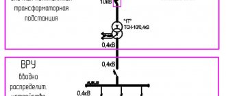
The formation of switching currents, for example, when starting powerful electric motors or other devices, is the most common cause of such failures. The figure below shows an example when a powerful motor is connected to a common power input with other consumers.
Formation of voltage dip when starting the electric motor
Designations:
- T1 – Step-down transformer.
- RZ – Power input impedance.
- RZ1-RZ3 - Impedances of consumer circuits.
- M – powerful asynchronous motor.
When the motor M is turned on, a starting current Istart is generated, the value of which exceeds the rated value (Istart > Inom). This leads to the formation of a failure zone with a significant decrease in voltage in the RZ1 circuit and minor deviations in the main distributor of the remaining consumer circuits.
Short circuits
The occurrence of short circuit currents in the electrical network also causes voltage deviations from the norm. Let us consider how the process proceeds and is determined in networks with different voltage classes.
Short circuit in low voltage networks.
An example of such a situation is illustrated in the figure below. In this case, the magnitude of the short-circuit current is affected by the impedances RZ and RZ2.
Formation of a gap due to a short circuit in consumer circuit 2
Based on this, we can say that the greater the impedance value in the low voltage network, the smaller the short-circuit current value will be.
In practice, in the event of a short circuit in the circuit of consumer 2, the protection of this group should be triggered. For example, if a circuit disconnection occurs after 50 ms, a 50 ms dip zone will form on the main distributor. That is, this parameter depends on the speed of protection operation. In this case, the depth of the failure will decrease with distance from the damaged area; accordingly, the closer the load, the greater the deviation. These rules apply to both low, medium and high voltage networks.
Short circuit in networks with medium voltage.
The most problems arise when a short circuit occurs in three-phase networks of medium voltage class. Despite the random nature of this phenomenon, the likelihood of an emergency occurring is quite high, since the influence of third-party factors cannot be excluded. These include:
- Various types of excavation work that may cause damage to the cable line.
- Breakdowns at connections.
- Aging of the insulating coating.
- Impact of natural and man-made factors.
When a short-circuit current is generated, it will flow until the automatic protective shutdown device at the distribution substation isolates the emergency area. Until this happens, the distribution substation network will experience a significant decrease in line voltages.
Short circuit in high voltage lines.
In most cases, short circuits in overhead lines occur due to exposure to natural factors (lightning, hurricane, etc.) or due to erroneous switching and false alarms of automatic protection.
Heavy loads
When connecting a large load to the electrical network, it can lead to the formation of inrush currents several times higher than the rated current. In cases where the electrical circuit is designed for the rated current, exceeding this parameter will cause a decrease in the amplitude of the power source. The scale of this manifestation directly depends on the power reserve of the electrical network and the magnitude of the impedance.
Network failures
Given the complexity of distribution circuits, it must be taken into account that if one section of the circuit is damaged, the remaining parts will be affected. In this case, the depth and duration of failures will be influenced by the following factors:
- circuit topology;
- the value of the impedance of the problem area;
- current power of the load and the source of electrical energy (generator).
For a more detailed view, consider the example presented in the figure below.
Network failures
Let's say a phase fault occurs at point P2, this will lead to the fact that consumer 1 will not experience any voltage deviations, consumer 2 will have a dip depth of 63%, and consumer 3 will have 97%.
If a single-phase fault occurs at point P1, then the depth of the dip will be 50% of the nominal value for all consumers, with the exception of consumer 1. That is, as we see, the higher the topology level where the damage occurred, the greater the number of consumers that fall into the voltage dip zone . Accordingly, for consumers connected to level 3, the risk of failure is significantly higher than for consumers powered from the first and second levels.
Criteria for assessing the supply network
What does GOST contain? The quality of electricity is determined by the characteristics of three-phase networks and common household circuits with a frequency of 50 Hz:
- The steady value of the voltage deviation determines the value of the characteristic at which consumers can function without failure. The lower normal limit is set from 220 V to 209 V and the upper normal limit to 231 V.
- The range of change in input voltage is the difference between the effective and amplitude values. Measurements are made per cycle of the parameter difference.
- The flicker dose is divided into short-term, within 10 minutes, and long-term, defined as 2 hours. Indicates the degree of susceptibility of the human eye to flickering light caused by power supply fluctuations.
- The pulse voltage is described by the recovery time, which has different values depending on the cause of the surge.
- Coefficients for assessing the quality of the supply network: sinusoidal distortion, temporary overvoltage values, harmonic components, reverse and zero sequence asymmetry.
- The voltage dip interval is determined by the recovery period of the parameter established in accordance with GOST.
- Deviation of the supply frequency leads to damage to electrical parts and conductors.
Electric energy quality indicators
The standard establishes the following power quality indicators (PQE):
- steady voltage deviation;
- voltage change range;
- flicker dose;
- voltage waveform sinusoidal distortion factor;
- coefficient n
th harmonic component of voltage;
- negative sequence voltage asymmetry coefficient;
- zero sequence voltage asymmetry coefficient;
- frequency deviation;
- duration of voltage dip;
- impulse voltage;
- temporary overvoltage factor.
When determining the values of some PKEs, the standard introduces the following auxiliary parameters of electrical energy:
- interval between voltage changes;
- voltage dip depth;
- frequency of voltage dips;
- pulse duration at a level of 0.5 of its amplitude;
- duration of temporary overvoltage.
Part of the PKE characterizes the steady-state operating modes of electrical equipment of the energy supply organization and consumers of EE and gives a quantitative assessment by CE of the features of the technological process of production, transmission, distribution and consumption of EE. These PCEs include: steady-state voltage deviation, sinusoidal distortion coefficient of the voltage curve, coefficient n-
oh harmonic component of voltage, negative sequence voltage asymmetry coefficient, zero sequence voltage asymmetry coefficient, frequency deviation, voltage change range.
All PCEs related to voltage are assessed based on their current values.
To characterize the above indicators, the standard establishes numerical normal and maximum permissible PKE values
or norms.
Another part of the PKE characterizes short-term interference that occurs in the electrical network as a result of switching processes, thunderstorm atmospheric phenomena, the operation of protective equipment and automation, and in post-emergency modes. These include voltage dips and pulses, short-term overvoltages. For these PKEs, the standard does not establish acceptable numerical values. To quantify these PCEs, the amplitude, duration, frequency of their occurrence and other characteristics established but not standardized by the standard must be measured. Statistical processing of this data makes it possible to calculate generalized indicators that characterize a specific electrical network in terms of the likelihood of short-term interference.
To assess the compliance of the PKE with the specified standards (with the exception of the duration of voltage dips, impulse voltage and temporary overvoltage coefficient), the standard establishes a minimum calculation period of 24 hours.
Due to the random nature of changes in electrical loads, the requirement to comply with CE standards during this entire time is practically unrealistic, therefore the standard establishes the probability of exceeding CE standards. The measured PCEs should not go beyond the normally permissible values with a probability of 0.95 for the calculated period of time established by the standard (this means that individual exceedances of standardized values can be ignored if their expected total duration is less than 5% over the established period of time).
In other words, the CE according to the measured indicator meets the requirements of the standard if the total duration of time exceeding the normally permissible values is no more than 5% of the established period of time, i.e. 1 hour 12 minutes, and beyond the maximum permissible values - 0% of this period of time.
The recommended total duration of PCE measurements should be selected taking into account the mandatory inclusion of workdays and weekends and is 7 days.
The standard identifies the likely culprits for the deterioration of CE. The frequency deviation is regulated by the power supply system and depends only on it. Individual electric power plants at industrial enterprises (and even more so in everyday life) cannot influence this indicator, since their power is disproportionately small compared to the total power of generators at power plants in the energy system. Voltage fluctuations, voltage asymmetry and non-sinusoidality are caused mainly by the operation of individual powerful electric power plants at industrial enterprises, and only the value of these electric power factor depends on the power of the supply power system at the consumer connection point in question. Voltage deviations depend both on the voltage level supplied by the power system to industrial enterprises, and on the operation of individual industrial electric power plants, especially those with high reactive power consumption. Therefore, CE issues should be considered in direct connection with issues of reactive power compensation. The duration of a voltage dip, pulse voltage, and temporary overvoltage coefficient, as already noted, are determined by the operating modes of the power system.
In table 2.1. The properties of electrical energy, their characterizing indicators and the most likely culprits for the deterioration of CE are given.
| Properties of electrical energy | CE indicator | The most likely culprits for the deterioration of FE |
| Voltage deviation | Steady-state voltage deviation | Energy supply organization |
| Voltage fluctuations | Voltage range Flicker dose | Consumer with variable load |
| Non-sinusoidal voltage | Distortion factor of the sinusoidal voltage curve Coefficient of the nth harmonic component of the voltage | Consumer with nonlinear load |
| Unbalance of three-phase voltage system | Voltage asymmetry coefficient for negative sequence Voltage asymmetry coefficient for zero sequence | Consumer with asymmetrical load |
| Frequency deviation | Frequency deviation | Energy supply organization |
| Voltage dip | Voltage dip duration | Energy supply organization |
| Voltage pulse | Pulse voltage | Energy supply organization |
| Temporary overvoltage | Temporary overvoltage factor | Energy supply organization |
The standard establishes methods of calculation and methods for determining PCE and auxiliary parameters, requirements for measurement errors and averaging intervals of PCE, which must be implemented in CE monitoring devices when measuring indicators and their processing.
Fixed input deviation
They try to make electricity quality indicators correspond to the established ratings prescribed in legislative acts. Attention is paid to the errors that arise when measuring U and f. If there are errors, you can contact the supervisory authorities to hold the electricity supplier accountable.
General requirements for power quality include the supply voltage deviation parameter, which is divided into two groups:
- Normal mode, when the deviation is ±5%.
- The permissible operating limit is set for fluctuations of ±10%. For a 220 V network, this will be a minimum threshold of 198 V and a maximum of 242 V.
Voltage restoration should occur within a time interval of no more than two minutes.
Electrical voltage standards according to GOST
The regulatory document defines several indicators that allow characterizing the quality of electricity at connection points (input into consumer networks). We list the most significant parameters and give the permissible deviation ranges for each of them:
- For a steady-state voltage deviation no more than 5.0% of the nominal value (permissible norm) for a long time period and up to 10% for a short-term anomaly (maximum permissible norm). Please note that these indicators must be specified in the contract for the provision of services, and these standards must comply with current standards. For example, for household networks (220 V) it should be in the range of 198.0-220.0 V, and for three-phase (0.40 kV) - no less than 360.0 V and no more than 440 Volts.
- Voltage drops, such deviations are characterized by the amplitude, duration and frequency of intervals. The normally permissible amplitude range should not exceed 10.0% of the norm. Changes also include the flicker dose (flickering of light due to voltage changes, causing fatigue), this parameter is measured by a special device (flickometer). The permissible short-term dose is 1.38, long-term - 1.
Example of established voltage deviation and fluctuation - Throws and failures . The first include short-term increases in voltage amplitude exceeding 1.10 nominal. The second phenomenon means a decrease in amplitude by more than 0.9 from normal, followed by a return to normal parameters. Due to the nature of the processes, these deviations are not standardized. If this occurs frequently, it is recommended to install a voltage limiter (to protect against surges) and a UPS (for frequent dips).
- Electrical network overvoltage, this definition means an excess of the nominal value by more than 10% lasting more than 10 milliseconds.
Examples of overvoltage and sag (A), surges (B) - Voltage unbalance . The permissible deviation of the asymmetry coefficient from the norm is 2.0%, the maximum is 4.0%.
- Non-sinusoidal voltage. It is determined by calculating the distortion coefficient, after which the resulting value is compared with standard values.
Example of voltage sinusoidality violation - Frequency deviations . According to current requirements, the normally permissible deviation of this parameter is 0.20 Hz, the maximum permissible is 0.40 Hz.
Range of supply network changes
Electricity quality standards contain oversight of such a parameter as fluctuations in voltage components. It sets the difference between the upper amplitude threshold and the lower one. Considering that the tolerances for deviation of the parameter from the set value are within the limit of ±5%, the range of the limit mode cannot exceed ±10%. The 220 V supply network cannot fluctuate more or less than 22 V, and 380 V works normally within ±38 V.
The resulting range of voltage fluctuations is calculated using the following expression ΔU = Umax−Umin; in the standards, the results are indicated in % according to calculations ΔU = ((Umax−Umin)/Unominal)*100%.
Permissible voltage dips according to GOST
According to GOST 32144 2013, to determine power quality indicators, failures should be classified according to two criteria:
- The magnitude of the residual stress.
- Duration.
Since the occurrence of dips is random, no numerical values have been established for the criteria presented above. However, amplitude and duration measurements should be carried out in order to create a statistical array that allows one to establish the probability of a random event for a certain power network in order to characterize the FE.
As for “failures permissible according to GOST,” this phrase does not make sense, since failure means a deviation from the norm established by GOST (0.9 Unom). To be precise, we can call normalization the permissible duration of the dip (30 s), above which the deviation is considered to be a low voltage.
Input instability
The power quality system includes flicker dose measurements. This indicator is recorded by a special device - a flicker meter, which records the amplitude-frequency response. The results obtained are compared with the sensitivity curve of the visual organ.
GOST establishes permissible limits for changing the flicker dose:
- Short-term fluctuations the indicator should not be higher than 1.38.
- Long-term changes must be within the parameter value of 1.0.
If we are talking about the upper limit of the incandescent lamp circuit indicator, then it is required that the result falls within the following limits:
- Short-term fluctuations - the indicator is set to 1.0.
- Long-term changes in the parameter - 0.74.
How to deal with voltage dips?
As we found out, failures are a random phenomenon, the duration of which depends on the operation of the protective systems, and the depth depends on the distance from the problem area. Since it is not possible to change the probability of occurrence, all that remains is to influence the scale of the failure and eliminate the consequences.
This can be done by optimizing the network to compensate for dips during sudden load changes, as well as installing special devices to monitor phase voltages for compliance with the nominal level and eliminating asymmetry. Stabilizing equipment installed at the electricity consumer is no less effective. More serious devices can act as a voltage regulator and a fundamental frequency converter.
If the problem is caused by short circuits, then installing an automatic reclosure system, and in case of critical failures, an automatic transfer switch, can reduce the maximum permissible duration of the deviation to a short interruption. That is, the automatic system will restart and if this does not produce a result, a reserve will be introduced.
We advise you to read and understand:
- Surge protection device in the apartment
- Full-wave rectifier bridge circuit
Tangible changes
Power quality measurements involve measurements of such a component as supply voltage pulses. It is explained by sharp drops and rises in electricity within the selected interval. The reasons for this phenomenon may be the simultaneous switching of a large number of consumers, the influence of electromagnetic interference due to thunderstorms.
Voltage recovery periods have been established that do not affect the operation of consumers:
- The reasons for the differences are thunderstorms and other natural electromagnetic interference. The recovery period is no more than 15 μs.
- If the pulses appeared due to uneven switching of consumers, then the period is much longer and equal to 15 ms.
The largest number of accidents at substations occurs due to lightning striking the installation. The insulation of the conductors immediately suffers. The magnitude of the overvoltage can reach hundreds of kilovolts. There are protective devices for this, but sometimes they fail and a residual potential is observed. At these moments, a fault does not occur due to the strength of the insulation.
The impact of failures on the operation of electrical equipment
This phenomenon is considered less dangerous deviations in frequency and voltage pulses, but, nevertheless, dips can lead to the following consequences:
- Reducing the intensity of the luminous flux produced by sources with a filament.
- Reduced sensitivity of radio and television receivers.
- Instability of X-ray installations.
- False alarms of electronic control systems.
- A decrease in the level of direct current in the contact network of electric transport has a negative impact on the operation of rolling stock.
- Changing the characteristics of voltage converters.
- A decrease in the power of electric motors, which leads to electrical losses and wear.
A failure depth of more than 10% of the permissible deviation will most likely cause the gas-discharge lighting sources to turn off. At low voltage, more than 15% of the permissible norm, the starters will open, which will cause a shutdown of electrical equipment and, as a result, lead to disruption of the technical process.
It is characteristic that dips do not have a serious impact on electric arc welding due to the large thermal inertia of the process, while the quality of spot welding is significantly reduced.
Input decay time
The measured parameter is described as a voltage dip that falls within the limits of ±0.1 Unominal over an interval of several tens of milliseconds. For a 220 V network, a change in the indicator is allowed up to 22 V, if 380 V, then no more than 38 V. The depth of decline is calculated according to the expression: ΔUn=(Unominal−Umin)/Unominal.
The duration of the decline is calculated according to the expression: Δtn=tk−tn, here tk is the period when the voltage has already been restored, and tn is the starting point, the moment when the voltage drop occurred.
Power quality control requires taking into account the frequency of failures, determined by the formula: Fn=(m(ΔUn,Δtn)/M)*100%. Here:
- m(ΔUn,Δtn) is defined as the number of falls at a specified time with depth ΔUn and duration Δtn.
- M is the total count of declines during the selected period.
What is a voltage dip?
In accordance with the definition given in GOST 13109-97, this phenomenon means a sudden decrease in voltage amplitude followed by dynamic restoration of power within the nominal value. An example voltage drop waveform is shown below.
Voltage dip oscillogram
Why is the decay value needed?
The parameter, the duration of the decay of the input value, is required to assess the reliability of the supplied energy in quantitative terms. This indicator may be influenced by the frequency of accidents at the substation due to personnel negligence and lightning. The result of the failure study is predictions of the degree of failure in the network under consideration.
Statistics allow us to draw approximate conclusions about the stability of the electrical energy supply. The electricity provider is provided with recommended data for carrying out preventive measures on installations.
Frequency deviation
Maintaining the frequency within certain limits is a necessary requirement of the consumer. If the indicator decreases by 1%, the losses are more than 2%. This is expressed in economic costs and reduced productivity of enterprises. For the average person, this results in higher amounts on their electricity bills.
The rotation speed of an asynchronous motor directly depends on the frequency of the supply network. Heating heating elements have lower performance when the parameter decreases below 50 Hz. If the values are too high, damage to consumers or other mechanisms not designed for high torque may occur.
Frequency deviation may affect the operation of electronics. Thus, interference appears on the TV screen when the indicator changes by ±0.1 Hz. In addition to visual defects, the risk of failure of microelements increases. A method of combating deviations in the quality of electricity is the introduction of backup power units, which allow automatic restoration of voltage at specified intervals.
Certification
Since the Federal Law “On Standardization in the Russian Federation” establishes the voluntary application of standardization documents , the protection of consumers’ rights to receive high-quality and safe electricity is guaranteed by the Law “On the Protection of Consumer Rights”: “If goods (work, services) are subject to law or as established it establishes mandatory requirements to ensure their safety for the life, health of the consumer, the environment and the prevention of harm to the consumer’s property; the compliance of goods (work, services) with these requirements is subject to mandatory confirmation in the manner prescribed by law and other legal acts.”
The Law “On Technical Regulation” defines: “The Government of the Russian Federation, before the date of entry into force of the relevant technical regulations, approves and annually updates a single list of products subject to mandatory certification and a single list of products subject to declaration of conformity.”
A unified list of products subject to mandatory certification and a unified list of products, confirmation of conformity of which is carried out in the form of a declaration of conformity, was approved by Decree of the Government of the Russian Federation of January 12, 2009 No. 982.
According to this resolution:
- is subject to mandatory certification: electrical energy in general purpose electrical networks of alternating three-phase and single-phase current with a frequency of 50 Hz - (code 01 1000/35.11.10.110);
- publication of information about products subject to mandatory confirmation of conformity, indicating regulatory documents establishing mandatory requirements, is ensured by the Federal Agency for Technical Regulation and Metrology.
In accordance with the information on products subject to mandatory confirmation of conformity posted by the Federal Agency for Technical Regulation and Metrology, the following defining regulatory document and requirements have been established in relation to electrical energy at points of transmission of electrical energy to users of low, medium and high voltage electrical networks of general purpose power supply systems AC 50 Hz:
- clause 4.2.1 GOST 32144-2013 - “The deviation should not exceed ±0.2 Hz during 95% of the time of an interval of one week and ±0.4 Hz during 100% of the time of an interval of one week”;
- clause 4.2.2 GOST 32144-2013 - “Positive and negative voltage deviations at the point of transmission of electrical energy should not exceed 10% of the nominal or agreed voltage value during 100% of the time interval of one week.”
The procedure for confirming conformity is established by the National Standard of the Russian Federation GOST R 58289-2018 “Conformity Assessment. Rules for certification of electrical energy." (approved by Order of the Federal Agency for Technical Regulation and Metrology dated November 29, 2018 No. 1038-st)
Odds
For normal operation of the supply network, control of the following coefficients has been introduced:
- Non-sinusoidal voltage curve. Distortion of the sine wave occurs due to powerful consumers: heating elements, convection ovens, welding machines. If this parameter deviates, the service life of the motor windings is reduced, the operation of relay automation is disrupted, and thyristor-controlled drive systems fail.
- Temporary overvoltage is a quantitative assessment of a pulse change in an input quantity.
- The Nth harmonic is the sinusoidal characteristic of the voltage characteristic obtained at the input. The calculated values are obtained from tabular data for each harmonic.
- It is important to take into account the asymmetry of the input quantity in reverse or zero sequence to eliminate cases of uneven phase distribution. Such conditions occur more often when the power supply network connected according to a star or delta circuit is broken.
Types of protection against unpredictable changes in the power supply network
Improving the quality of electricity must be carried out within the time limits specified by law. But the consumer has the right to protect his equipment using the following means:
- Power stabilizers guarantee that the input value is maintained within the specified limits. Quality energy is achieved even with input value deviations of more than 35%.
- Uninterruptible power supplies are designed to maintain the functionality of the consumer for a specified period of time. The devices are powered by the accumulated energy in their own battery. In the event of a power outage, uninterruptible power supplies are capable of maintaining the functionality of the equipment of an entire office for several hours.
- Surge protection devices operate on the relay principle. After the input value exceeds the set limit, the circuit opens.
All types of protection have to be combined to ensure complete confidence that expensive equipment will remain intact during an accident at a substation.