Dear site visitor, client and simply colleague, we often receive a request to count the ASU of the main switchboard. Today I want to draw a fine line of difference between these two technical concepts.
Device
The main switchboard is installed on the line immediately after the substation. Its task is to introduce and redistribute incoming energy between consumers or other devices. Additionally, it keeps track of energy consumption and ensures the safety of lines from short circuits and voltage surges.
The main distribution board consists of several modules, the operating range of which is up to 4000A. Additionally, elements for receiving and distributing energy are installed. They are needed to seamlessly connect other electrical appliances to the network.
The internal configuration is modified in any order. Therefore, it is equipped with elements, the list of which depends on the technological needs of the facility.
- AVR block. It provides connection to the network of backup power sources in case of emergency.
- Accounting panel. Monitors the amount of electricity consumed.
- Elements of protection. Connected for the safety of life and property. They come in several types: fuses, relays, lightning protection and others.
- Measuring instruments. Installed for service purposes to measure current characteristics in the system.
- Signal block. In case of emergency, notifies maintenance personnel.
An ASU is a complex device that is simultaneously responsible for the input and distribution of electricity. At the same time, depending on the units included in the composition, it carries out accounting, control and protection of the system from short circuits and voltage surges.
The design differs from the main switchboard in its dimensions. If in the latter case the shield is a large cabinet of several boxes with panels, then the ASU is only one box with several panels. Therefore, they have more limited functionality.
The specific device is also determined by the needs of the support object. The shield is modified by panels, each of which is responsible for performing separate tasks.
- Input block. It is used to input electricity and is equipped with protective and switching equipment.
- AVR module. As in the main switchboard, it is responsible for the timely connection of backup power sources.
- Accounting module. Controls and tracks the amount of resources consumed.
- Lighting control panel. Includes components that manually or automatically turn on/off lighting, for example, when evening falls or in dark areas of the territory.
- Fire-fighting equipment. Provides electricity to devices responsible for triggering fire alarms, extinguishing fires, and illuminating escape routes.
Thus, the main switchboard and ASU devices are formed by individual blocks. Many of them perform the same functions, so both shields can replace each other.
Application difference
In fact, main switchboard and ASU are a formal designation of the functionality of the device. The manufacturer produces one piece of equipment, and during installation it is assigned a corresponding role. Therefore, the regulatory framework implies the use of input distribution devices as main switchboards.
The functions of the shields are almost the same. This is due to the fact that the specific list of tasks to be performed is formed independently by the staff by adding the necessary modules. Therefore, both devices can take into account the amount of electricity consumed, as well as ensure the safety of consumers from short circuits and voltage surges.
The difference in application is that the main switchboard is located higher in the hierarchical chain of the power supply system and can control the operation of other electrical appliances. Let’s say that modules installed in the main switchboard can monitor the correct functioning of the ASUs included in the circuit. If an emergency occurs, it will automatically disconnect the device from the system, and after the problem is resolved, it will turn it on again.
What are these 3 devices?
1. VU – input device. 2. ASU – input distribution device. 3. Main switchboard - main distribution board.
They belong to the same type of electrical equipment, since they have the same purpose in electrical circuits - they receive electricity from transformers, electrical substations, and branches of power lines at sites and distribute it to end consumers.
VU, ASU and main switchboards differ in their configuration, additional functions and some other characteristics.
Input devices
In the VU there are no devices that divide the power supply circuit into several branch circuits; one cable enters and leaves the device. In this case, input devices can be equipped with equipment to provide protection against overloads and short circuits, as well as to account for electricity consumption. Regardless of the configuration, the input device must be equipped with an electrical disconnector, with the help of which the internal electrical circuit is disconnected from the general power supply circuit. Circuit breakers or switches can be installed as a circuit breaker. Input devices are most often used in private homes; they are mounted on power poles or on the façade of buildings. In this case, meters for recording consumed electricity are installed in a specially designed remote cabinet.
Input distribution devices
ASUs are equipped with electrical disconnectors, as well as devices that divide the main power supply line into a certain number of branching internal electrical circuits. Also, input distribution devices are equipped with devices for monitoring and accounting for electricity consumption, as well as automatic devices to provide protection against voltage surges, overloads and short circuits.
Main switchboard
This electrical panel equipment is widely used in multi-storey buildings, public and administrative buildings, production and industrial facilities, and other structures where it is necessary to receive electricity from a common power line and distribute it over a large number of consumption sources. The main switchboard can replace the input distribution device or input device if the power supply of a private house is being installed.
You should be aware that energy regulatory authorities may require the installation of meters outside the house, on its façade or on a power pole. It must be mounted in a lockable cabinet with a high level of security.
Source
ASU is a special case of a main switchboard.
ASU is an input-distribution device, often combined with a metering unit. The main switchboard is the main distribution board; it can be separate, but its functions can also be performed by an ASU (if the location allows for a switchgear section). Those. The main switchboard is the first distribution board of the facility (!), after the ASU (or combined with it), starting from the power source. All subordinate switchboards of one object (in economic terms) are distribution switchboards (whether lighting, power equipment, etc.). Subsubscribers, if any, have their own ASU, usually with their own commercial or technical electricity metering units, which can also perform the functions of a main switchboard, or an ASU + separate main switchboards.
Main switchboard and ASU: main differences
An important group of devices included in the power supply system are switchboards. They connect the end consumer with the energy source. Thanks to the shields, users receive electricity with the required characteristics and are protected from short circuits and voltage surges.
Shields can be classified according to various parameters: configuration, installation method, dimensions and general functionality. Two types of devices are considered the most important: main distribution boards and input distribution boards. They perform almost the same functions: they are responsible for energy input, its metering and redistribution, ensure line safety and timely response in the event of an incident.
Experts often argue about the differences between ASU and main switchboard. The difficulty is that the regulatory framework for the concepts of these devices is almost identical, and the addition that the role of the main switchboard can be performed by an ASU device is completely confusing. Therefore, the difference between these shields should be determined through their design and functionality.
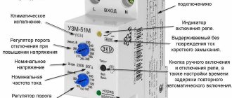
Let's look at each element of the ASU in more detail.
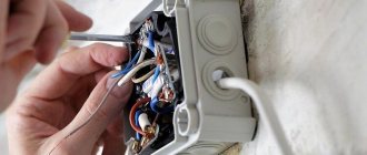
Copper busbars for connecting PE and N conductors in the ASU at home
All wires are connected to the PE copper busbar using bolts, washers, nuts and lock washers. The connection must be made using a tool and not by hand.
The copper PE busbar must have connection points
- Input PEN wire, with a TN-CS house power supply system;
- Grounding conductor from the grounding of the house;
- Conductor from the potential equalization system;
- Wire from the arrester (voltage limiter).
Copper bus N is intended for connecting zero working conductors of the home network
In the input distribution device (IDU), the PE and N buses are connected to each other, but according to certain rules.
Connection of PE and N buses in the ASU at home
Let me remind you that I am considering an ASU at home when connecting the power according to a TN circuit, with a solidly grounded neutral.
The tires are mounted inside the ASU next to each other. According to the recommendation in GOST R 51732-2001 (VRU), the zero operating bus (N) should be located below the PE bus, but, in my opinion, this is not of fundamental importance. The fundamental thing here is different.
Important! The PE bus must be secured to the ASU body using bolted connections and a conductive contact. Bus N must be secured to the ASU body through dielectric (non-conducting) insulators.
The PE and N buses must be connected by two jumpers at the edges of the buses or one jumper in the middle. The cross-section of the jumpers must be no less than the cross-section of the protective PE wires. The connection must be bolted.
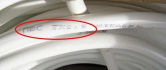
PE and N busbars must be marked with color or signs with the inscriptions PE and N. Wires extending from the busbars must have a color in accordance with GOST R 50462: protective PE wires in green-yellow, neutral working wires N in blue.
Introductory machine ASU
The power cable is connected to the input automatic switch ASU. The rating of the machine is selected according to the electrical design. The input circuit breaker is designed to protect the electrical wiring of the house from overload and ultra-high short circuit currents, as well as deliberate power outages for maintenance of the home network. Instead of an input circuit breaker, it is possible to install fuses.
Arresters (voltage limiters)
The arresters are installed after the introductory machine. Through them, the phase wires are connected to the PE protective bus. During pulse overloads, the arresters are triggered. The phase voltage reaches the PE bus and the ASU protection is triggered.
Blocks of machines for electrical groups at home
These circuit breakers are designed to distribute power across groups of electrical wiring in a home. For each electrical group of the house (kitchen, bathroom, rooms, lighting, etc.) a separate circuit breaker is installed. If necessary, residual current devices (RCDs) are installed.
Distribution machines must be installed in such a way as to evenly distribute the load between the phases. The number of machines for each phase must be calculated taking into account the demand coefficient. The demand factor determines the probability that all electrical networks will be at maximum load. (Read about demand factor in detail).
Equipment
It should be noted that the configuration of ASUs for residential, public and office buildings differs from the configuration of devices for industrial facilities. But in all models, inlet panels and distribution panels must be installed. In fact, this is where the name itself comes from – an input distribution device. The connection diagram for all is almost standard.
For public buildings
Let's start by noting that the equipment of water-type panels is designed for current strength: 250, 400 and 630 amperes. Therefore, panels of the VR, VA or VP type are most often installed for these devices.
Distribution panels can also have different configurations. Eg:
- With automatic machines on the outlet networks.
- With the addition of staircase and corridor lighting. Used as a separate line.
- Accounting and control of current consumption can be carried out separately or along lines.
Distribution panels and input panels are usually located next to each other. This refers to single input panels.
ASU diagram
For production
It should be noted that industries, especially large ones, consume a lot of power. Therefore, input and distribution cabinets are used here as ASUs, which are manufactured in factories according to specifications or GOSTs. Most often, ASUs are installed either one-sided or two-sided. At the same time, AVM automatic machines are mounted on the input installations, and A37 on the distribution ones.
Attention! Single-sided panels are installed against the walls. Double-sided at a distance of at least 80 cm from the wall. The one-sided ASU panel is compact, the two-sided one is easy to maintain.
It should be noted that ASU devices can be manufactured at the factory in a modular manner. This is when, for example, a block of automatic machines is installed separately, a block with control counters is installed separately, a block with fuses is installed separately, and so on.
Some requirements for premises where ASU devices should be installed.
- Only authorized service personnel may enter the room where the input distribution device is installed.
- A gas pipeline should not pass through this room; other communication networks can be laid, but only without connections. There should be no valves, valves or other shut-off valves here.
- Do not install ASUs in damp and damp rooms, especially in those where there is a high probability of flooding.
- The devices can also be installed on staircases or corridors. True, a cabinet of this type must be locked to prevent unnecessary entry. In this case, all handles of controlled devices must be removable or located inside the box.
Marking
Installation of switchgear
The decoding of the switchgear itself indicates that the installations are immediately produced in kits, and they do not need to be assembled from disparate elements. The manufacture of switchgear is carried out at a specialized enterprise. Complete switchgears are delivered to the location in the form of solid cabinets or enlarged blocks (3-5 chambers assembled together), completely ready for installation. Recently, mixed switchgear, consisting partly of prefabricated and complete elements, has been widely used.
The installation process consists of several sequential activities:
- Preparing the foundation.
- Assembly of structures for lighting points of free-standing protective panels and electrical devices.
- Preparation of the internal grounding network and general lighting network of the switchgear.
- Placement of switchgear units. Each cell is installed in a specific place according to the plan. Installation begins with the outermost element. The individual blocks are connected to each other by attaching the side walls to each other.
After completion of installation work, it is mandatory to check the oil level in the tanks of the switches, the correct operation of all main and auxiliary elements and blocking devices. The entire process must be carried out in accordance with the manufacturer’s instructions attached to the equipment.
After making sure that the entire device is assembled correctly (particular attention is paid to ensuring that the cells are not located at an angle), high-voltage cable lines are brought to the terminals on the rear door of the switchgear and secured with end sleeves.
Why is a main distribution board needed?
The main tasks of the main distribution board are the reception and distribution of electricity between individual consumers. Consumers are also protected from excess supply voltage in the event of a network failure, and energy sources and transmission lines are protected in the event of load failures.
For your information! Depending on the load category, there may be a need for a continuous supply of electricity, so switchgear must be able to automatically or manually switch to a backup power line or, for special requirements, to a backup source of electrical energy (petrol or diesel autonomous power plant).
Reserve power plant
Floor (SHE)
This electrical panel is designed for installation in multi-storey residential buildings. It allows you to distribute power to 2-6 apartments.
As a rule, such equipment consists of several main elements:
- subscriber camera
. Protective fuses are installed in it; - recording cameras
. It is used for installing meters; - low current camera
. It installs equipment for the Internet and cable television.
The products are used for metering, receiving and distributing electricity. The equipment also allows you to protect household appliances from voltage surges. Such devices are developed taking into account current requirements for resistance to increased loads and the number of group lines for one apartment.
Water distribution devices
ASU are devices that provide the reception and distribution of electricity in a building at a voltage of less than 1000 V of single- and three-phase current with a frequency of 50-60 Hz. They also serve to protect lines from high currents resulting from overload or short circuit. Input and distribution devices (one or more) are installed at the entrance to the building. If there are several separate consumers in it, it is recommended to install separate ASUs for each of them.
For an ASU there are restrictions on the maximum input current - no more than 630 A. This is one of the main differences from the main switchboard, which is designed for large performance and has no restrictions on the input currents and outgoing supply lines.
The ASU is equipped with various devices and devices: circuit breakers, switches, load switches, fuses, meters and other functional equipment. The input distribution device ensures the prompt connection and disconnection of individual consumers (parts of buildings), as well as various devices and devices, from electricity.
Main switchboard decoding, device, purpose. What is the difference between an ASU and a main switchboard?
Main distribution boards are designed for full or partial redundant power supply, three-phase alternating current with a rated operating voltage of 380 V and a frequency of 50 Hz in public and industrial buildings.
What is the difference between an ASU and a main switchboard?
There are many devices in the electrical distribution system. Each of them has its own characteristics and purpose. But certain categories are so closely intertwined that it is difficult to tell the difference. First of all, this concerns electrical switchboard equipment. Here two concepts are often confused - ASU and main switchboard . Even experts cannot always immediately identify the differences, although they probably feel the difference on an intuitive level.
Indeed, the main distribution board ( MSB ) and the input distribution device ( IDU ) are very similar in their design features and functional purpose. Both are designed to receive and distribute electricity. Both are equipped with protection and current characteristics monitoring devices. But still, there are two abbreviations, which means that there is a difference between these concepts. Let's figure out how the ASU from the main switchboard ?
Electrical switchboard equipment has its own hierarchy. And the first input device, of course, is considered the main one. It controls the distribution of electricity between all subsequent panel devices in this hierarchy. So the difference in theoretical concepts is that the main switchboard is at the very top stage, and all subsequent links in this electrical panel circuit are ASU . In practice it looks like this. Immediately after the transformer or boiler room there is a main switchboard . And at the entrances to buildings and on floors, ASUs . But within a specific scheme it may be different: at the entrance to the building there is a main switchboard (main distribution board), and on the floors there is an ASU . That is, these concepts determine only the position of a link in the chain, the level in the hierarchy at which this or that switchboard equipment is located.
The practical side of this issue can be explained even more simply. During manufacture, electrical panel equipment is marked. Along with the serial number and other information, it will almost certainly say “ VRU ”. But when installed at the site as the main electrical panel, this equipment will be marked “ main switchboard ”. And in the project documentation it will appear the same way. That is, it turns out that the ASU is the designation of the product, and the main switchboard is the functional purpose that this product performs.
In fact, the information provided makes it possible to answer the popular question: “what is at the entrance to the building - an ASU or a main switchboard? ". If after the first ASU , which is located at the entrance to the building, there are more ASUs , then a hierarchy arises. Then the first ASU will become the main one and will appear on the diagrams as the main switchboard . If the ASU is the only one, then it is permissible to use both the abbreviation ASU and main switchboard . That is, formally this ASU will be the main one, but at the same time the only one. So in this case, you can emphasize its functional purpose by designating it on the diagram as main switchboard , or simply use the name of the product - ASU .
But these are not all the differences between the ASU and the main switchboard . There is also a formal difference in the permissible current characteristics. It is worth noting here that both concepts are in the PUE (clauses 7.1.3 and 7.1.4) . In addition, these concepts are used in the set of rules (SP 31-110), where there are references to GOSTs. So, if we summarize the information from all this documentation, it will become clear that there are current limitations for the ASU. Thus, the maximum input current should not exceed 630A, and the maximum load on each supply line extending from the ASU should not exceed 250A. At the same time, for switchboard (main distribution board) there are no restrictions on input and output currents. By the way, this confirms the information that the main switchboard is not the name of the product, but only a designation of the ASU as part of the electrical network circuit.
Thus, the concepts of ASU and main switchboard refer to the same type of devices and with the same purpose. But at the same time, these are not synonymous words. The use of one or the other of them will depend on what you want to emphasize - the purpose of the device (that is, the main switchboard as the main ASU ) or its relationship to a certain type of device (a product called ASU ). This is the fundamental difference.
Typical power supply system with main switchboard at the top level
Main distribution board (MSB) - Main switchboard , through which electricity is received and distributed throughout the building or some part of it. As we noted above, an input distribution device or a low voltage switchboard of a substation can serve as a main switchboard. The main switchboard contains emergency automation (for example, circuit breakers or RCD devices), and electricity metering devices (meters).
Main distribution boards the MSB type are manufactured in a multi-cabinet floor-mounted design, designed for the distribution of electrical energy, protection of electrical installations with voltages up to 660 V AC with a frequency of 50, 60 Hz.
The main distribution boards of main switchboards are most often located in the power supply system of a building (structure) at the upper level of power distribution with a voltage of 0.4 kV.
Source
Application area
In fact, ASU switchgears can be used at any facility. This could be manufacturing or residential construction. Here it is important to accurately select the device itself in terms of power consumption and voltage in the supply network. All these parameters are usually indicated in the design documentation. That is why the assembly of the ASU is a crucial moment, which is carried out according to strict and stringent requirements. In this case, the shield (cabinet) itself can be assembled as a device, precisely adjusted to those very requirements. By the way, the assembly process itself is done only by hand. You can also purchase standard-type models on the market that are suitable for certain parameters of the consuming and supply networks.
Lighting board (SHB)
Devices of this type allow you to control lighting fixtures. Most often, such equipment is installed in large non-residential buildings: shopping centers, food hypermarkets, etc. Based on the principle of their operation, the devices resemble standard switches. The equipment may be equipped with fuses and power meters.
Energy distribution in an apartment building with a TN-C system
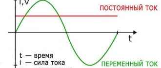
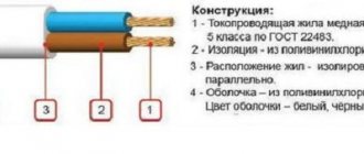
TN-C is an outdated system, but it is actively used in old houses. This is a four-wire system consisting of three voltage phases and a combined neutral and working conductors (L1, L2, L3, PEN). In this PEN system, the conductor cannot be split and is delivered to the consumer in this form. It is also worth noting that quite often phase wires are given the names A, B, C.
As a result, with such a power supply system, with a single-phase connection, the consumer is connected with two wires (L, PEN), and with a three-phase connection with four (L1, L2, L3, PEN).
A power cable runs underground from the substation to the house. The cable enters the input box connected to the distribution board:
The risers laid vertically will extend from it. On each floor, floor panels will be connected to the risers, from which the apartments will be supplied with electricity.
Inputs can be made in various ways, this directly depends on the number of floors and size of the house, on the cable laying system (in the collector or in the ground). Why is that? Yes, because the load of a house with 100 apartments will be significantly lower than a house with 500 apartments. Moreover, the power supply requirements of, for example, a five-story building are relatively small - there are no elevators in the building and there is no need to install additional pumps to maintain water pressure, which cannot be said about a 30-story building where elevators and water supply pumps cannot be left without power.
It is for these reasons that not one, but two or more power supply cables with mutual redundancy can be installed in large houses. Distributing electrical energy between common building loads (elevators, entrance lighting, pumps) and apartments is a rather complex and time-consuming task. Distribution is carried out using complete electrical devices, the mounting methods, dimensions and installation locations of which are coordinated with the designs of the houses.
Let's look at options for connecting apartments to risers in apartment buildings with a TN-C system. The riser has four wires - three phases and one PEN conductor, designated in the diagram as A, B, C and PEN:
Between phases (A-B, C-B, C-A) the voltage will be 1.73 or more than between any of the phases and the neutral conductor (zero). From here we calculate the voltage between phase and neutral - 380/1.73 = 220 V. Two wires enter each of the apartments - phase and neutral. The current in both of these wires will be exactly the same.
They try to connect the load (in our case, apartments) evenly to different phases. In Figure a), out of six apartments, two are connected to each phase. Uniform connection makes it possible to reduce the neutral conductor current and avoid phase imbalance.
In old houses, combined electrical cabinets were sometimes used instead of floor panels. An example of such a cabinet is shown below:
This cabinet has compartments with separate doors. In one compartment there are signs with apartment numbers, switches and circuit breakers. In another there are meters, in the third there are low-current devices such as telephones, networks of television antennas, twisted pair cables for intercoms, the Internet and other devices.
In such a floor panel, each apartment has one switch and two automatic switches (the first for the general lighting line, and the second for plug sockets). Some versions of electrical cabinets may have a plug socket with a protective contact for connecting various machines (for example, cleaning machines).
How does the main switchboard work?
The main switchboard is a metal cabinet containing:
- input terminals for connecting the power line;
- output terminals for connecting the load;
- busbars or wires;
- switching devices;
- circuit breakers;
- RCD;
- energy monitoring and metering devices;
- devices for automatic switching to reserve;
- reactive power compensation devices.
Depending on the requirements, there can be a huge number of types of main switchboards. The simplest and most universal option works like this:
- The power cable is connected to the input terminals of the panel.
- A main switch is installed between the input terminals and the distribution busbars.
- Individual consumers are connected to the busbar trunkings through separate circuit breakers. In this case, the ratings of the machines must correspond to the load power.
- When the main switch is turned on, the busbars are energized; with the help of circuit breakers, power can be switched for each consumer separately.
Note! A malfunction of one of the consumers will trigger the corresponding circuit breaker, so the rest of the load will be provided with power regardless of the state of the faulty part.
Emergency input of backup power (ABP)
This equipment is designed to switch consumers from the main power source to a backup one in case of emergency situations. ATS must be used in hospitals and other institutions where continuous power supply is of great importance. Also, devices of this type can be installed in cottages.
Most often, 2 subtypes of electrical panels are used:
- priority
. It only has one power supply; - non-
priority In such equipment, the main functions can be performed by any power source.
Personal preferences should be taken into account when choosing certain models. It is also important to know all the features of the electrical network.
Cell benefits
The special advantages of switchgear, which allowed them to displace earlier models of similar equipment and become widespread, include:
- increased reliability;
- increasing the speed of installation work;
- reduction of time and labor costs;
- reducing the amount of required design work;
- simplification of operation and repair of the installations themselves;
- the ability to quickly and conveniently connect other switchgear;
- the presence of a locking system that is triggered in the event of incorrect operator actions.
It is important that all these advantages appear only if the equipment is installed in accordance with the rules and regulations specified in the technical documentation.
ASU production
Our production is located in Moscow. The customer can always come and see the assembly of the ordered ASU. You can also simply come to our production site and see the full assembly cycle of switchgear devices. The device production cycle consists of:
- Approval of schemes with the customer
- Selection of equipment and order completion
- Assembly of switchboard equipment
- Panel marking
- Testing on a test bench
- Delivery to the quality control department and packaging
Comparison of ASU and main switchboard by technical capabilities
Taking into account the fact that the main switchboard in conjunction with the ASU are part of the overall system, and the first one in the hierarchy is the main one, the comparison looks like this:
In terms of safety characteristics, both devices comply with current regulations. An ASU can be installed as a main switchboard if the technical characteristics of the selected device are not lower than the values required during operation.
When purchasing a switchgear, make sure that there is an image of its electrical circuit on the inside of the protective cover.
Source
Types of input distribution devices
The last thing I would like to talk about in this article is what types of ASUs there are. So, we roughly divided them into the following types:
- By rated current: 100, 250, 400, 630 A.
- By type of execution: suspended, floor-mounted.
- By purpose: input, distribution, input-distribution.
- According to installation location: indoors and outdoors. It is important to point out here that the degree of protection can be from IP31 to IP65.
- By type of service: single-sided, double-sided.
- By the number of inputs: for 1 input or for several (2, 3, 4).
It is important to note that the distribution devices themselves can be one-, two-, three-panel or more (multi-panel). The dimensions of the box also depend on its configuration and area of application.
The ASU marking makes it clear what characteristics this device has. The abbreviation stands for as follows:
Finally, we recommend watching a video that explains in more detail how the UVR works:
This is where we end our article. We hope that now it is clear to you what the input distribution device is used for and what design options exist. We hope the information provided was useful and interesting for you!