Page 8 of 33
QUALITY OF ELECTRIC ENERGY 4.1. GENERAL PROVISIONS Power supply systems and electrical receivers are designed in such a way that the best functioning is achieved when they are powered from a single-phase or symmetrical three-phase system with a voltage of a given amplitude and sinusoidal shape with a frequency of 50 Hz. However, in real electrical networks, for known reasons, deviations from ideal parameters occur, which leads to deterioration in the operation of electricity consumer installations, manifested in technical and economic damage. Inattention to the quality of electricity during the operation of power plants leads to a progressive breakdown of the power supply and disruption of the operation of electrical receivers. Deviations in power quality indicators are also the result of the impact of consumer electrical installations on the ES. Power quality indicators can be divided into two groups. The first group includes deviations of frequency and voltage from the nominal ones, eliminated by power supply systems.
The second includes frequency and voltage fluctuations, asymmetry and distortion of the shape of voltage and current curves, which manifest themselves mainly in areas affected by special electrical receivers that cause these distortions. The degree of this influence is determined by the ratio of the power of these electrical receivers and the parameters of the electrical system. In addition, there are electrical receivers that are sensitive to various types of interference. The conditions in which this interference occurs are not constant, since the ES in combination with consumer installations are constantly evolving: the parameters of the systems, the composition and power of electrical receivers change. Therefore, the quality of electricity is the object of control. Compliance with the quality of electricity is associated with the use of: a rational system of quality indicators that determine the limits of deviations and electromagnetic compatibility of equipment connected to the general network; measuring instruments that allow you to easily assess the quality of electricity and outline reasonable measures to improve it; technical means to improve the quality of electricity; methods for optimal management of power quality in power plants. Deviations from ideal performance should be limited. Therefore, there are norms for permissible deviations, fixed in state standards for power quality. These standards have been adopted in all developed countries, and taking into account the experience and development of power supply and power consumption systems, they are gradually changing in relation to real conditions. In the USSR, power quality indicators at network points to which receivers are connected are standardized by GOST 13109-87. It is necessary to standardize the quality of electricity in power supply nodes, which are the boundaries of the balance sheet of networks. Deviations of power quality indicators from ideal are divided into normal and maximum permissible. During 95% of the day (22.8 hours), power quality indicators should not go beyond the limits of normally permissible values, and during the entire time, including post-emergency modes, they should be within the maximum permissible values (Table 4.1). In emergency situations in the ES, it is allowed for quality indicators to go beyond the established limits, including a decrease in voltage to zero level and a frequency deviation of up to ±5 Hz, with their subsequent restoration to the maximum values permissible for post-emergency modes.
*Rozenkron Y. K., Bimanis V. V. Temperature and current protection of transformers from emergency and systematic overloads // Electrical engineering, 1985, No. 8, pp. 36-38.
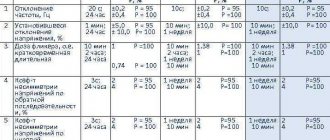
Table 4.1. Permissible deviations of power quality indicators
| Indicator name | Acceptable value of the indicator | |
| normal | maximum | |
| Frequency deviation, Hz | ±0,2 | ±0,4 |
| In post-emergency modes, a frequency deviation of ±0.5... - 1 Hz is allowed, the total duration per year is no more than 90 hours | ||
| Voltage deviation (%) in the electrical network voltage, kV: | When determining voltage deviation, voltage dips and voltage pulses are not taken into account | |
| UP TO 1 | ±5 | ±10 |
| 6—20 | — | ±10 |
| In transient mode, short-term voltage deviations outside the established limits are permissible | ||
| Voltage fluctuation range (%) (see §4.3): at the inputs of lighting installations with incandescent lamps in rooms where significant visual stress is required, and at points of electrical networks to which consumers with such installations are connected at the inputs of lighting installations with incandescent lamps in in other premises, including in residential buildings and at points of electrical networks to which consumers with such installations are connected at the inputs of lighting installations with fluorescent lamps and other receivers of electrical energy and at points of electrical networks to which consumers with such installations and receivers are connected | — | According |
| with curve 1 Fig. 4.13 In accordance | ||
| with curve 2 Fig. 4.13 In accordance with curve 3 of Fig. 4.13 | ||
| Dose of voltage fluctuations (%2) in the electrical network to which lighting installations are connected: | The indicator “dose of voltage fluctuations” in existing electrical networks is introduced as they are equipped with appropriate devices, using which the assessment of the permissibility of the range of voltage changes at the inputs of lighting installations is assessed according to the curves in Fig. 4.13 it is allowed not to produce | |
| with incandescent lamps in rooms where significant visual strain is required | 0,018 | |
Continuation of the table. 4.1
| Acceptable value of the indicator | ||
| Indicator name | normal | maximum |
| with incandescent lamps in other rooms | — | 0,034 |
| with fluorescent lamps | — | 0,079 |
| Non-sinusoidal coefficient (%) in the electrical network voltage, kV (see § 4.5): | ||
| UP TO 1 | 5 | 10 |
| 6—20 | 4 | 8 |
| 35 | 3 | 6 |
| 110 and above | 2 | 4 |
| Coefficient of the harmonic component of voltage of odd (even) order (%) in an electrical network with voltage, kV (see § 4.6): | ||
| UP TO 1 | — | 6 (3) |
| 6—20 | — | 5 (2,5) |
| 35 | — | 4 (2) |
| 110 and above | — | 2 (1) |
| Negative voltage sequence factor (%) (see § 4.4) | 2 | 4 |
| Zero sequence voltage factor (%) (see § 4.4) | 2 | 4 |
At the inputs of receivers that are sources of electromagnetic interference, the values of quality indicators may exceed acceptable limits, if this does not lead to a violation of the standard for other power receivers.
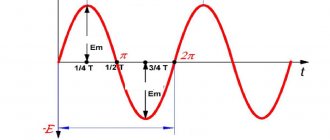
Voltage deviation
The voltage deviation is normalized only at the ED inputs, that is, in fact, only in 0.4 kV networks and at some points in 6–10 kV networks to which high-voltage motors can be connected. They are characterized by the “steady-state voltage deviation” indicator, which is the average voltage deviation over an interval of 60 s. Normal and maximum permissible values of steady-state voltage deviation are equal to ±5% and ±10% of the rated voltage of the electrical network, respectively.
The values of the steady-state voltage deviation in the TOP in networks of 6–10 kV and above should be set taking into account the need to comply with GOST standards at the ED inputs. This means that voltage deviations in other networks are not numerically normalized; they are obtained as a result of calculations.
3.1. INSTRUCTIONS FOR PREVENTION AND ELIMINATION OF ACCIDENTS AT THERMAL POWER PLANTS
3.1. Reducing the frequency of current in the power system
3.1.1. The frequency of electric current in power systems must be maintained at 50 Hz with deviations of +/- 0.1 Hz. A decrease in frequency in the power system occurs due to a shortage of generated power or due to a disconnection of intersystem and intrasystem electrical connections.
A deep decrease in frequency below 49.0 Hz is unacceptable according to the operating mode of boilers at thermal power plants with electric feed pumps. With a prolonged, more than 1 minute, decrease in frequency below 48 Hz (specified in the organization’s instructions), there is a threat of failure of feed pumps and shutdown of power units from technological protections.
A decrease in frequency worsens the operating mode of the blade apparatus of powerful turbines and shortens the service life of the blades.
Operation at a reduced frequency can lead to damage to block transformers, excitation system components and other electrical equipment.
3.1.2. The following system automation is used to maintain the frequency and prevent the development of accidents, the presence (or absence in a given system) of which is known to the operating personnel of the power plant in order to make the right decisions:
1) frequency control system;
2) devices for automatic frequency start-up, loading and switching on of reserve power of CHAPV power plants (hydroelectric power plants, pumped storage power plants, gas turbine units). These operations (secondary regulation), along with loading the units of thermal power plants and taking permissible overloads by order of the dispatcher, can also be performed manually. The load and reserve power switching settings are in the range of 49.3 - 49.8 Hz;
3) special AFC queue with a frequency setting of 49.3 - 49.0 Hz, in the case when it is not possible to prevent a decrease in frequency through the action of the AFC or operational actions and regulation of turbines (prevention of frequency reduction to the upper AFC II settings);
4) AChRI (fast-acting) with different frequency settings to stop reducing the frequency (46 - 47 Hz), AChRII - slow-acting with different frequency and time settings to increase the frequency after AFCI operation (after AFCII operation, the frequency should increase to more than 49.3 Hz) . In addition, additional AFR is applied in the event of a local, local power shortage (it operates without waiting for the frequency to decrease). It acts selectively only for local deficiencies.
If the frequency as a result of the AFR action does not increase above 49.3 Hz, the staff takes additional emergency measures;
5) to prevent complete extinction of the area and eliminate an accident with a deep decrease in frequency (for example, for thermal power plants with cross connections, steps of 45 - 46 Hz, 0.5 s and 47 Hz, 30 - 40 s are used), frequency dividing automatics (FDA) are used . It ensures preservation in work with. n. power plant, prevents its complete shutdown. In this case, the power plant or its part is allocated with an approximately balanced load, or individual units (unit) are allocated to power their own needs.
3.1.3. To prevent a possible decrease in frequency or overload of intersystem and intrasystem connections, the expected balance of power during the period of maximum load is received from the dispatcher with an analysis of this balance and recommendations for its prevention. For thermal power plants, in the event of an expected power shortage and a possible reduction in frequency, the following measures can be taken if necessary:
a command was given to turn around power equipment from cold reserve;
preparations for the removal of generating equipment for repairs have been suspended;
generating and other electrical equipment, the absence of which reduces power output, has been taken out of repair within the limits of emergency readiness.
3.1.4. If the frequency decreases to 49.9 Hz and, despite the dispatcher entering a power reserve (backup hydraulic units, pumped storage power plants, etc.), decreases to 49.8 Hz, the dispatcher ensures frequency restoration by limiting consumers according to the instructions.
Under these conditions, power plant personnel ensure, if necessary, that the power of all operating generators is increased to the value required to maintain frequency. In this case, special attention should be paid to the reduction in frequency compared to a long-established reduced frequency level.
3.1.5. When working with a frequency in the range from 49.8 to 49.3 Hz, when the reserve available in the power system must be introduced automatically or manually, and a sudden decrease in frequency relative to the previous steady value by 0.1 Hz or more, the power plant shift supervisor immediately requests permission from the dispatcher to load the thermal power plant, takes measures to implement his order (full loading of operating units, switching on rotating reserve units, see clause 3.1.3, etc.).
3.1.6. When operating with a frequency ranging from 49.3 to 49.1 Hz and a sudden decrease in frequency by 0.1 Hz, but not lower than 49.1 Hz (reservation in the power system is insufficient or cannot be fully introduced, the AFR special queue may have been triggered), The shift manager of the power plant immediately requests permission from the dispatcher to fully mobilize power reserves and takes measures to implement his orders (further reduction in frequency will lead to the operation of the AFC and the loss of power to a significant number of consumers). In the absence of communication with the dispatcher, the personnel ensures that the full load is set independently, including on generators taken out of reserve. If, after gaining power, the frequency continues to decrease, the thermal power plant personnel on units with a rotating reserve independently increases the load until possible overloads are reached.
Loading is stopped at the command of the system manager. The on-duty personnel of the thermal power plant immediately reports to the dispatcher of the energy association about all changes in the loads of the power plant and about the achievement of maximum loads on the power lines extending from the thermal power plant. When receiving an order from the dispatcher to suspend loading or reduce the load of units, the thermal power plant personnel on duty immediately carries out the order, ensuring unloading at the maximum permissible speed.
3.1.7. If the frequency, despite the measures taken, does not rise above 49.3 Hz, the operating personnel of the power plant independently, followed by notifying the dispatcher:
raises, if this has not already been done, the full electrical load on all units that were operating previously and put into operation from reserve (including units with a heating load);
handles possible emergency overloads on generators and other equipment;
puts into operation electrical equipment taken out of repair into reserve within the limits of emergency preparedness (see clause 3.1.3);
delays shutdowns for repairs and transfer of units to reserve;
takes measures to turn on disconnected but still rotating steam turbines, as well as boilers under pressure.
3.1.8. In case of a large loss of generating capacity and a sharp decrease in frequency, if, despite the operation of the AFC, the frequency remains at the level of 49 - 48.9 Hz and below, restrictions on independent actions of the operating personnel of power plants for the emergency mobilization of reserve power of overloading units (if it still remains) are lifted. disabling part of the mechanisms c. n. (mills, etc.) to increase power.
In this mode, the decisive role is played by the dispatcher responsible for frequency regulation, who after 3 - 5 minutes. (time sufficient to use the remaining reserves) increases the frequency of disconnecting consumers, while preventing overload of intra-system and inter-system connections. In this case, shutdowns are carried out at the direction of the dispatcher in all power systems. At the direction of the dispatcher, the consumers specified by him are disconnected from the power plant buses.
3.1.9. When the frequency decreases to 47.5 Hz and further decreases to a specific value specified in the organization’s instructions, electric power is allocated to prevent a complete shutdown of thermal power plants. n. for non-synchronous power supply from one or two power plant generators disconnected from the network. It is also possible to separate a power plant or part of it with an approximately balanced load of a power grid area in which the nominal frequency will be restored. This allocation is made by the action of frequency dividing automatics AChD or independently by the shift supervisor of the power plant with notification of the power system dispatcher. Operating modes with the transfer of one or two turbogenerators to electric power supply. n. turbogenerators remaining in operation or with the allocation of a part of turbogenerators to power a limited area of the electrical network with a rated frequency that guarantees the preservation of at least one turbogenerator in operation, are indicated in the emergency response instructions developed by the organization.
Conditions under which it is necessary to highlight s. n. when the frequency decreases, they are indicated in the power plant instructions. The main diagram of the electrical network and the order of allocation of turbogenerators are also indicated there.
3.1.10. When determining the specific scheme of the allocated part. n. the following basic provisions are taken into account:
transformers feeding the village. n. from dedicated generators provide power to the. n. two or three neighboring units;
The dedicated power units include power units equipped with ROU, providing steam power. n.
3.1.11. The operation of dedicated turbogenerators providing electrical power. n. special control is established for their own and neighboring power units included in the network. In particular, maintaining the nominal rotation speed of turbogenerators is carried out not only by automatic turbine frequency regulators, but is controlled both from the control room and locally.
In the event that there is a threat of emergency shutdown of turbogenerators, boilers (due to pressure and temperature of steam or feed water, vacuum, after the expiration of the operating time of turbines at a reduced frequency and other reasons), which are not connected for their own needs with dedicated turbogenerators, they are unloaded and separated from electrical networks together with mechanisms c. n. and load of consumers before their parameters require a complete shutdown.
3.1.12. In case of a sharp decrease in frequency, accompanied by a deep decrease in voltage, as a result of which conditions may be created for the failure of automatic frequency unloading (especially on alternating operating current), the power plant shift supervisor independently takes measures to allocate his own needs for non-synchronous power supply (see clause 3.1 .9).
3.1.13. With a significant decrease in frequency in the power supply system and the operation of automatic frequency unloading, dividing automation and emergency automation, a sharp change in frequency occurs. Operating personnel in this case:
keeps generators in the network (or separated sections of the network) or, if there is a threat of their emergency shutdown, unloads them, disconnects them from the power grid and transfers them to load. n.;
participates in the regulation of frequency and voltage by emergency increase or decrease of loads (active and reactive) with control of the load of transit lines and communication autotransformers, the permissible overloads of which are indicated in the organization’s instructions;
When performing switching in electrical circuits, it excludes the combination of circuits with asynchronous voltages, which can be on the busbars of outdoor switchgear of different voltages or in busbar systems of the same voltage, as well as on sections of devices with. n. needs 6 and 0.4 kV;
does not allow loss of electrical and steam power. n. power plants.
3.1.14. An emergency reduction in frequency to 46 Hz or less can lead to a complete shutdown of the power plant. In this case, the personnel, if the emergency control devices are not working or are missing, take measures to keep at least one power unit in operation to ensure the subsequent turnaround of the power plant in accordance with the organization’s emergency instructions.
Voltage fluctuations
Voltage fluctuations are characterized by two indicators:
- voltage change range;
- flicker dose.
The permissible range of voltage changes depends on the frequency of occurrence of the ranges and is normalized by the curve in Fig. 8.18. The curve was obtained based on an assessment of the negative impact of flashing incandescent lamps on human vision and is not related to other electronic devices, although it normalizes voltage fluctuations in the network as a whole. The application of this curve does not encounter difficulties with the same amplitudes of the swings, repeated after certain periods of time. Usually, the ranges of voltage changes in the TOC are chaotic; their amplitudes and frequencies of occurrence are formed by many EPs and direct application of the curve in Fig. 8.18 becomes impossible. A procedure is used to weigh fluctuations and obtain an integral indicator, which is called the “flicker dose”. This procedure is quite complex, can be implemented only with the help of special devices (flicker meters) and is of interest mainly for developers of these devices and therefore is not considered here. In the presence of voltage fluctuations, the sum of the steady-state voltage deviation δUy and the range of voltage changes δUt at points of connection to electrical networks with a voltage of 0.4 kV should not exceed 10% of the rated voltage.
What are the dangers of frequency fluctuations in the electrical network?
The frequency of alternating current used by the world's electricity consumers allows for two standards. In almost all countries of both Americas, Saudi Arabia and a number of island countries, the power supply frequency is 60Hz; in other countries, including Russia, electrical equipment consumes alternating current at an industrial frequency of 50Hz. Physically, the frequency of the alternating current of the electrical network can be easily represented in the form of the rotation frequency of power plant generators, or more precisely, their moving parts - rotors.
This is one of the most important parameters characterizing the electrical network; it is not without reason that frequency deviations are given special attention in the power quality standard. Among long-term voltage deviations from nominal parameters, frequency fluctuations come first, and only then does attention focus on voltage deviations. The GOST 32144-2013 standard establishes the maximum deviation of the frequency value from the accepted 50 hertz, which is ±0.4Hz. In this case, the nominal frequency values must be within 50±0.2Hz.
What is the danger of deviations from normally acceptable values?
To assess the damage that the fact of change, in particular reducing the frequency of alternating current, can bring, the problem should be considered in two aspects: technological and electromagnetic. In both options, a change in frequency results in economic losses, causing material damage to one degree or another.
In the first case, a decrease in frequency leads to disruption of technological processes associated with a slowdown in the operation of production equipment. This is illustrated by frequency converters - frequency regulators designed for smooth starting of powerful electric motors. Thus, at best, the productivity of the equipment decreases, at worst, it leads to the production of defects.
Electromagnetic losses are associated with changes in the balance of reactive and active powers. This negatively affects the efficiency of electrical equipment, for example, a decrease in the frequency of the supply network by 1% is accompanied by a decrease in the load power of an asynchronous motor by 3%.
Deviations from the fundamental frequency have an adverse effect on electrical equipment with electrical steel cores. Heating of magnetic circuits leads to general heating of electric motors and power transformers, which generally affects equipment resources.
The own technological equipment of power plants is also critical to frequency reduction. With significant deviations (46 ... 45 Hz) associated with a decrease in active power, a so-called “frequency avalanche” occurs and the power system shuts down.
Situations that are dangerous for electrical equipment occur in cases of increased frequency, which usually occurs when consumers sharply reduce the electrical energy load. Excess power is primarily dangerous for power plant equipment. An increase in the frequency of the supply voltage leads to an increase in the rotation speed of an asynchronous type motor, but the torque decreases. If there is no power reserve, this leads to braking of the electric motor, up to a complete stop.
In the amateur community, there is a misconception that the quality of the insulation is critical to changes in frequency, causing it to age. This does not coincide with reality, since isolation is afraid of the influence of higher harmonics, but deviations of several hertz are not afraid of it. The cause of destructive processes in the insulation material is caused by poor sinusoidality of the voltage due to the presence of harmonics that are multiples of the frequency of the main voltage. True, harmonics have a negative impact on the equipment itself, which determines the need to combat this phenomenon.
In our company you can order a power quality measurement; you can view information about the cost and procedure for carrying out the work here
Still have questions?
Fill out the feedback form below, our specialists will contact you, advise you, and tell you about possible ways to solve your problem.
order a consultation
Non-sinusoidal voltage
Non-sinusoidal voltage is characterized by two indicators:
- voltage waveform sinusoidal distortion factor;
- coefficient of the nth harmonic component of voltage.
These indicators are defined as values averaged over an interval of 3 s.
Rice. 8.18. Permissible voltage fluctuation ranges
The sinusoidal distortion coefficient is determined by the formula, %:
The harmonic values are normalized to n = 40. The permissible KU values are given in table. 8.4.
Table 8.4
Acceptable values of sinusoidal distortion coefficient
Normally permissible values of the coefficient of the nth harmonic component of voltage are given in table. 8.5.
Table 8.5
Normally permissible values of the coefficients of harmonic components
Normally permissible values given in table. 8.5 for n equal to 3 and 9 refer to single-phase electrical networks. In three-phase three-wire electrical networks, these values are taken to be half those given in the table.
The maximum permissible values of the coefficients of the harmonic components of voltage are 1.5 times higher than the normally permissible values.
Voltage asymmetry
Voltage asymmetry is characterized by two indicators:
- negative sequence voltage asymmetry coefficient;
- zero sequence voltage asymmetry coefficient.
These indicators are defined as values averaged over an interval of 3 s.
The normally permissible and maximum permissible values of both voltage asymmetry coefficients are 2.0 and 4.0%, respectively. The zero sequence asymmetry coefficient makes sense only for four-wire electrical networks of 0.4 kV; the standards for the negative sequence asymmetry coefficient are the same for networks of any voltage.