Upon conclusion:
- agreements with an energy sales organization (ESO) for the sale of electrical energy and capacity according to the “energy supply” type
- agreement with the territorial grid organization (TGO) for the provision of services for the transmission of electrical energy
it is necessary to determine the tariff level (range, class) of voltage (CAR) at which the electricity consumer is connected to TSO networks, since according to the tariff voltage level, the value of the tariff for the transmission of electricity or the value of the maximum levels of unregulated prices for electricity, including the tariff for transmission of electricity.
In my opinion, when identifying the tariff level (range) of voltage that determines the size of the tariff for transmission services, the following circumstances must be taken into account:
- The concepts of “voltage level” and “voltage” are different concepts
- The concepts “actual voltage level” and “actual voltage” are different concepts
- When determining the actual voltage level, it is necessary to take into account where the balance line (hereinafter referred to as GBP) is located: at the “power source” or not?
- An algorithm for determining the value of the electricity transmission tariff used for calculations when directly connecting the consumer’s power receiving devices (hereinafter referred to as EPU) to TSO power grid facilities
The evolution of network voltage - where it all began
The level of standard voltages has constantly changed over the past 100 years for domestic household networks, depending on the degree of technological development. Thus, at the dawn of the electrification of the countries of the Soviet camp, a nominal value of 127 V was set for consumers of electrical energy. This system of nominal parameters came into use thanks to the developments of Dolivo-Dobrovolsky, who proposed three-phase generation instead of the outdated two-phase. It should be noted that back in the late 30s of the last century, the voltage standard of 127 V already poorly corresponded to the increased production needs, it was then that the first attempts to replace it arose, but with the outbreak of World War II, these plans were never realized.
But already in the 60s, large-scale work began to bring the rated voltage to the new standard 220/380 V instead of three-phase alternating 127/220 V. European networks, by that time, had already made a massive transition to new ratings in order to avoid unreasonably costly replacement of wires with larger section. In an attempt to remain as efficient as possible, the Soviet countries also began a transition that was planned to be completed within the next five years. There was construction of new power plants, replacement of transformers and power units, but the process of transition to standards of 220 V phase voltage for household consumers dragged on until the 80s.
Socket rating
In 1992, GOST 29322-92 (IEC 38-83) introduced new voltage standards: 230 V phase instead of 220 V and 400 V linear instead of the usual 380 V.
This step was pursued by the desire to bring our own energy system on par with foreign ones for:
- convenience of working with immediate neighbors;
- opportunities for unhindered access to world markets;
- simplifying the transit procedure.
But, due to the imperfection of the entire domestic power supply system and the lack of funds for full-scale reconstruction, these voltage standards have not been established to this day.
Classification of electrical networks according to the principle of construction
According to the principle of construction, electrical networks are divided into closed and open.
An open network is a set of open lines receiving power from one common power source IP on one side (figure below):
Its main disadvantage is the interruption of power to all electrical receivers in the area where the outage occurred due to a line break.
In a closed system, the opposite is true - power comes from two power supply sources and if the main line breaks anywhere, the power supply to the electrical receivers will not stop. The simplest diagram of a closed network is shown below:
For example, in the event of a line break at point K, power receivers 1,2,3,4 will receive power from the upper line, and 5,6,7,8 from the bottom. Depending on the requirements for reliability of power supply, closed systems may have one or more power sources. Below is an example of a circuit with two-way power supply:
Disagreements in GOSTs
How can it be that there are norms, new requirements are given in the standard, but practical implementation has not come even after almost thirty years. The reason for this was the constant increase in the power of household appliances, their number and growing consumption. Therefore, power supply organizations could not even achieve the permissible deviations of the previous standard rated voltage.
The first of the standards under consideration is GOST 32 1 44-2013, intended to determine the main parameters of the quality of electrical energy. As one of these indicators, the standard establishes acceptable ranges for potential differences.
Of course, it makes no sense to consider all the points and their calculation part, so we will discuss the most important points:
- according to clause 4.2.2, the rated voltage is considered to be 220 V between phase and zero, and 380 V for the linear norm.
- voltage dips, which, as a rule, are caused by the introduction of powerful consumers, the duration of the dip should not exceed 1 minute;
- in accordance with clause 4.3.3, pulse overvoltages, which can be caused by atmospheric discharges, range from 1 microsecond to several milliseconds;
- the asymmetry of the three-phase network according to clause 4.2.5 should be no more than 2 - 4% of the asymmetry coefficient in a ten-minute interval according to the weekly characteristic.
For comparison with previous standards, GOST 29322-2014 is in force, which refers to international standards and establishes the nominal characteristics of voltage series. It was developed in accordance with other standards - IEC 60038:2009 and repealed the 1992 standard. But in it, according to clause 3.1, the rating of household energy networks is set at 230 V and 400 V for electrical networks with alternating current with a frequency of 50 Hz. It is worth saying that for foreign networks with a frequency of 60 Hz there are some differences, but the permissible frequency deviation is only 2%, so these amendments are irrelevant for domestic consumers.
The concepts of “voltage level” and “voltage” are different concepts
“Voltage” is a technical characteristic of a power plant; it indicates what voltage the electronic control unit is designed to receive. It is measured in volts (V) or kilovolts (kV). Predetermined by technical conditions, design on the EPU. Primarily, as a rule, the voltage is recorded in documents on technological connection, most often in acts of delimitation of balance sheet ownership. In our country, EPUs are designed to accept the following “voltage”:
- 0.4 kV
- 1 kV
- 6 kV
- 10 kV
- 20 kV
- 35 kV
- 110 kV
- 150 kV
- 220 kV and above
“Voltage level” (sometimes “voltage range” or “tariff voltage level” or “tariff voltage level (range)”) is a concept used:
1. in tariff regulation – when setting tariffs for electricity transmission
2. in the application of electricity transmission tariffs in payments for electricity transmission services
according to “voltage levels” , that is, they differ in size. The higher the “voltage level” , the lower the tariff. Therefore, consumers seek to confirm the highest “voltage level”.
The concept of “voltage level” in regulatory legal acts (hereinafter referred to as legal acts) appears and is used in the context of tariff setting and tariff application.
According to paragraph 48 of the Rules for non-discriminatory access to services for the transmission of electrical energy and the provision of these services, approved by Decree of the Government of the Russian Federation No. 861 of December 27, 2004, (hereinafter referred to as the IPA), “tariffs for services for the transmission of electrical energy are established in accordance with the Pricing Fundamentals in area of regulated prices (tariffs) in the electric power industry and the Rules of state regulation (revision, application) of prices (tariffs) in the electric power industry, taking into account paragraph 42 of these Rules"
In accordance with paragraph 42 of the IPA, “when setting tariffs for services for the transmission of electrical energy, tariff rates are determined taking into account the need to ensure equality of uniform (boiler) tariffs for services for the transmission of electrical energy for all consumers of services located on the territory of the corresponding constituent entity of the Russian Federation and belonging to one group (category) from among those for which the legislation of the Russian Federation provides for differentiation of tariffs for electrical energy (power).”
Differentiation of tariffs for electricity transmission by “ voltage levels ” is established by the following regulations:
- The principles of pricing in the field of regulated prices (tariffs) in the electric power industry, approved by Decree of the Government of the Russian Federation of December 29, 2011 No. 1178 “On pricing in the field of regulated prices (tariffs) in the electric power industry” (hereinafter referred to as the Fundamentals of Pricing)
- Methodological guidelines for calculating regulated tariffs and prices for electric (heat) energy in the retail (consumer) market, approved by Order of the Federal Tariff Service of August 6, 2004 N 20-e/2 (hereinafter referred to as the Twentieth Methodology):
Paragraph 81(1) of the Pricing Framework states: “Unified (boiler) tariffs are differentiated according to the following “ voltage levels ”:
- high voltage (HV) - power grid facilities (110 kV and above);
- average first voltage (CH1) - power grid facilities (35 kV);
- average second voltage (CH2) - power grid facilities (20 - 1 kV);
- low voltage (LV) - power grid facilities (below 1 kV).”
Paragraph 44 of the Twentieth Methodology establishes: “The size of the tariff for electric energy transmission services is calculated in the form of an economically justified rate, which in turn is differentiated by four “voltage levels” :
- at high voltage: (HV) 110 kV and above;
- at average first voltage: (CH1) 35 kV;
- at average second voltage: (CH 11) 20 - 1 kV;
- at low voltage: (LV) 0.4 kV and below"
From the indicated points of the regulatory legal acts it is also clear that each “voltage level” has its own voltages that relate to it:
- voltage level - high voltage (HV) includes voltages from 110 kV and above (i.e. 150 kV, etc.)
- the voltage level - the average first voltage (CH1) refers to only one voltage - 35 kV
- the voltage level - average second voltage (CH2) includes voltages whose values fall in the range: 20-1 kV, i.e. - this is 1 kV, 6 kV, 10 kV, 20 kV, etc.
- Voltage level - low voltage (LV) includes voltages whose values are 0.4 kV and below (for example, 220 V, 150 V, etc.)
The maximum levels of unregulated electricity prices, which include the electricity transmission tariff, are also differentiated by voltage levels. This can be seen from the form of publication of data on the maximum levels of unregulated prices for electrical energy (power) and the components of the maximum levels of unregulated prices for electrical energy (power), established by the Appendix to the Rules for the determination and application by guaranteeing suppliers of unregulated prices for electrical energy (power), approved Decree of the Government of the Russian Federation dated December 29, 2011 No. 1179 “On the determination and application by guaranteeing suppliers of unregulated prices for electrical energy (power)” (hereinafter referred to as the Rules for determining unregulated prices)
Thus, the concepts of “voltage” and “voltage level” are not identical. These are different concepts. But they are often confused, especially when determining the tariff for electricity transmission, at which payment for transmission services provided by territorial grid organizations (hereinafter referred to as TGO) is subject to payment. This also happens because the concepts of “actual voltage level” and “actual voltage” are confused.
What is the network voltage
Since 2003, a standard voltage of 230V should have appeared in the sockets of our apartments and private houses. But for the past 17 years this transition has not been completed.
From September 30, 2014, instead of GOST 29322-92, GOST 29322-2014 (IEC 60038:2009) was adopted, establishing what the standard voltage should be in Russia. Now its value is 230 V (±10%) at a frequency of 50Hz (±0.2). But still quite often there is 220 V in the electrical network instead of the expected 230 V.
The rated parameters of AC power networks up to 1000 V are indicated in the table given in GOST 29322-2014.
In the first and second columns, the smaller values are the voltage between phase and neutral (phase), the larger values are between phases (linear). If one value is specified, it is the voltage between phases of a three-phase three-wire system.
The standard voltage of 230/400 V appeared as a result of the evolution of the 220/360 V and 240/415 V systems. Currently, the 220/360 system is no longer used in Europe and other countries, but 220/380 V and 240/415 V are still actively used.
The change in standards was caused by the need to bring electricity into full compliance with European parameters to facilitate the export and import of electricity and electrical devices.
All about energy
The rated voltages of electrical networks, sources and receivers of electrical energy of direct and alternating current of industrial frequency are determined by a set of documents: GOST 23366, GOST 721, GOST 21128, GOST 6962 and GOST 29322.
Range of standard voltages
A number of standard voltages are established by GOST 23366 for direct and alternating current of industrial frequency. The voltage at the terminals of the designed equipment must correspond to the values of this series, with the exception of some cases [3, clause 2]. Below are the standard range of voltages for electrical energy consumers
[3, table 1].
The main series of voltages of direct and alternating current of electric energy consumers is presented in Table 1, the auxiliary series of voltages of alternating current - in Table 2, and of direct current - in Table 3. Table 1 - Series of voltages of direct and alternating current of electric energy consumers
| No. | U, V | No. | U, V |
| 1 | 0,6 | 14 | 1140 |
| 2 | 1,2 | 15 | 3000 |
| 3 | 2,4 | 16 | 6000 |
| 4 | 6 | 17 | 10000 |
| 5 | 9 | 18 | 20000 |
| 6 | 12 | 19 | 35000 |
| 7 | 27 | 20 | 110000 |
| 8 | 40 | 21 | 220000 |
| 9 | 60 | 22 | 330000 |
| 10 | 110 | 23 | 500000 |
| 11 | 220 | 24 | 750000 |
| 12 | 380 | 25 | 1150000 |
| 13 | 660 |
Table 2 - Auxiliary range of AC voltages for electrical energy consumers
| No. | U, V |
| 1 | 1,5 |
| 2 | 5 |
| 3 | 15 |
| 4 | 24 |
| 5 | 36 |
| 6 | 80 |
| 7 | 2000 |
| 8 | 3500 |
| 9 | 15000 |
| 10 | 25000 |
| 11 | 150000 |
Table 3 - Auxiliary range of DC voltages for electrical energy consumers
| No. | U, V | No. | U, V | No. | U, V | No. | U, V |
| 1 | 0,25 | 11 | 24 | 21 | 300 | 31 | 5000 |
| 2 | 0,4 | 12 | 30 | 22 | 400 | 32 | 8000 |
| 3 | 4,5 | 13 | 36 | 23 | 440 | 33 | 12000 |
| 4 | 1,5 | 14 | 48 | 24 | 600 | 34 | 25000 |
| 5 | 2 | 15 | 54 | 25 | 800 | 35 | 30000 |
| 6 | 3 | 16 | 80 | 26 | 1000 | 36 | 40000 |
| 7 | 4 | 17 | 100 | 27 | 1500 | 37 | 50000 |
| 8 | 5 | 18 | 150 | 28 | 2000 | 38 | 60000 |
| 9 | 15 | 19 | 200 | 29 | 2500 | 39 | 100000 |
| 10 | 20 | 20 | 250 | 30 | 4000 | 40 | 150000 |
Standard range of voltages for sources and converters (for example: generator, transformer, etc.) of electrical energy
[3, table 2].
The range of voltages for alternating current is given in Table 4, for direct current - in Table 5. Table 4 - Range of AC voltages of electrical energy sources and converters
| No. | U, V | No. | U, V |
| 1 | 6 | 15 | 10500 |
| 2 | 12 | 16 | 13800 |
| 3 | 28,5 | 17 | 15750 |
| 4 | 42 | 18 | 18000 |
| 5 | 62 | 19 | 20000 |
| 6 | 115 | 20 | 24000 |
| 7 | 120 | 21 | 27000 |
| 8 | 208 | 22 | 38500 |
| 9 | 230 | 23 | 121000 |
| 10 | 400 | 24 | 242000 |
| 11 | 690 | 25 | 347000 |
| 12 | 1200 | 26 | 525000 |
| 13 | 3150 | 27 | 787000 |
| 14 | 6300 | 28 | 1200000 |
Table 5 - Range of DC voltages of electrical energy sources and converters
| No. | U, V | No. | U, V |
| 1 | 4,5 | 8 | 230 |
| 2 | 6 | 9 | 460 |
| 3 | 12 | 10 | 600 |
| 4 | 28,5 | 11 | 1200 |
| 5 | 48 | 12 | 3300 |
| 6 | 62 | 13 | 6600 |
| 7 | 115 |
When choosing voltage, preference should be given to the main series.
Rated voltage of electrical equipment up to 1000 V
The rated voltage of equipment up to 1000 V is regulated by GOST 21128. A number of rated voltages are given in Table 6 [2, p.2].
Table 6 - Rated voltage of sources, converters, power supply systems, networks and receivers up to 1000 V
| Type and type of current | Rated voltage, V | |
| sources and converters | power supply systems, networks and receivers | |
| Constant | 6; 12; 28,5; 48; 62; 115; 230; 460 | 6; 12; 27; 48; 60; 110; 220(230); 440 |
| Variable: | ||
| single-phase | 6; 12; 28,5; 42; 62; 115; 230 | 6; 12; 27; 40; 60; 110; 220(230) |
| three-phase | 42; 62; 230; 400; 690 | 40; 60; 220(230); 380(400); 660(690); (1000) |
Note:
The voltage values for electrical networks are indicated in parentheses according to [6, table 1]
Rated voltage of electrical equipment over 1000 V
The rated voltage of electrical equipment over 1000 V is regulated by GOST 721. A number of rated voltages are given in Table 7 [1, p.3].
Table 7 - Nominal phase-to-phase voltages for networks with voltages above 1000 V
| Networks and receivers, kV | Generators and synchronous compensators, kV | Transformers and autotransformers without on-load tap-changer, kV | Transformers and autotransformers with on-load tap-changer, kV | Highest operating voltage of electrical equipment, kV | ||
| Primary windings | Secondary windings | Primary windings | Secondary windings | |||
| (6) | (6,3) | (6) and (6.3)* | (6.3) and (6.6) | (6) and (6.3)* | (6.3) and (6.6) | (7,2) |
| 10 | 10,5 | 10 and 10.5* | 10.5 and 11.0 | 10.0 and 10.5* | 10.5 and 11.0 | 12,0 |
| 20,0 | 21,0 | 20,0 | 22,0 | 20.0 and 21.0* | 22,0 | 24,0 |
| 35 | — | 35 | 38,5 | 35 and 36.75 | 38,5 | 40,5 |
| 110 | — | — | 121 | 110 and 115 | 115 and 121 | 126 |
| (150)* | — | — | (165) | (158) | (158) | (172) |
| 220 | — | — | 242 | 220 and 230 | 230 and 242 | 252 |
| 330 | — | 330 | 347 | 330 | 330 | 363 |
| 500 | — | 500 | 525 | 500 | — | 525 |
| 750 | — | 750 | 787 | 750 | — | 787 |
| 1150 | — | — | — | 1150 | — | 1200 |
Note:
1. The voltages indicated in brackets are not recommended for newly designed networks and electrical installations; 2. Voltages marked “*” for transformers and autotransformers connected directly to the generator voltage buses of power plants or to the generator terminals;
In the Russian Federation, two voltage systems (kV) have historically developed:
- 110 — 330 — 750
- 110 — 220 — 500 — 1150
The first voltage system (110 - 330 - 750) prevails in the western part of the Russian Federation, and the second (110 - 220 - 500 - 150) - in its eastern part. In the networks of the central part of the Russian Federation there is no obvious predominance of one voltage system over another; this is a kind of transition zone.
Rated voltage of traction systems (electrified transport)
The rated voltage for electrified transport is regulated by GOST 6962 and GOST 29322. Table 8 shows a number of rated voltages for traction substations and pantographs of electrified transport [4, page 3][6, table 2].
Table 8 - Rated voltages of traction substations and current collectors of electrified transport
| Type of electrified transport | Voltage, V | |||
| on the busbars of a traction substation | on the current collector of electrified transport | |||
| Railways | ||||
| Trunk: AC | (27500) | 25000 | ||
| direct current | (3300) | 3000 | ||
| Industrial: AC access and quarry tracks | (27500) | 25000 | ||
| access, quarry and in-plant DC tracks | (3300) (1650) (600) | 3000 1500 600 (550) | ||
| Urban electrified transport | ||||
| metro | (825) | 750 | ||
| tram, trolleybus | (600) | 600 (550) | ||
Note:
Voltage values are indicated in parentheses according to [4, page 3]
Permissible voltage deviations
In reality, during the operation of electrical networks, sources, converters and consumers of electrical energy, the voltage on them differs from the nominal parameters. This may be due to disruption of the normal operation of equipment, losses of electricity during transmission, etc. GOST 29322-2014 partially regulates the permissible voltage deviation values.
For electrical equipment with a voltage of 100 ÷ 1000 V, this range is limited to ±10% [6, table 1].
In other words, for a kettle designed for a rated voltage of 230 V, operation is allowed when the voltage increases up to 252 V and drops to 198 V. More details below, in Table 9 [6, Table A.1]. Table 9 - The highest and lowest voltages of sources and receivers of electrical energy with a voltage of 100 ÷ 1000 V inclusive
| Systems | Rated frequency, Hz | Voltage, V | |||
| Rated voltage of electricity sources and receivers | The highest voltage sources and receivers of electricity | Lowest voltage power sources | Lowest voltage of electricity receivers | ||
| Three-phase three-, four-wire systems | 50 | 230 | 253 | 207 | 198 |
| 230/400 | 253/440 | 207/360 | 198/344 | ||
| 400/690 | 440/759 | 360/621 | 344/593 | ||
| 1000 | 1100 | 900 | 860 | ||
| 60 | 120/208 | 132/229 | 108/187 | 103/179 | |
| 240 | 264 | 216 | 206 | ||
| 230/400 | 253/440 | 207/360 | 198/344 | ||
| 277/480 | 305/528 | 249/432 | 238/413 | ||
| 480 | 528 | 432 | 413 | ||
| 347/600 | 382/660 | 312/540 | 298/516 | ||
| 600 | 660 | 540 | 516 | ||
| Single-phase three-wire systems | 60 | 120/240 | 132/264 | 108/216 | 103/206 |
Permissible voltage deviations for traction systems (electrified transport) are given in Table 10 (source - [6, Table 2]).
Table 10 - Highest and lowest voltage of traction systems
| System type | frequency Hz | Voltage, V | ||
| Nominal | Greatest | Least | ||
| DC systems | — | 600* | 720* | 400* |
| 750 | 900 (975) | 500 (550) | ||
| 1500 | 1800 (1950) | 1000 (1100) | ||
| 3000 | 3600 (3850) | 2000 (2200) | ||
| Single-phase AC systems | 50 or 60 | 6250* | 6900* | 4750* |
| 16 2/3 | 15000 | 17250 | 12000 | |
| 50 or 60 | 25000 | 27500 (29000) | 19000 | |
Note:
1. Rated voltages marked “*” are not recommended for newly designed networks and electrical installations; 2. Voltage values are indicated in parentheses according to [4, p. 3]
For electrical equipment with a voltage of 1 ÷ 35 kV, GOST 29322-2014 establishes a permissible deviation of approximately ±10% [6, table 3].
Permissible voltage deviations for electrical equipment of 35 ÷ 230 kV are partially regulated by GOST 29322-2014, and for electrical equipment with voltages above 230 kV they are not regulated at all. But this, generally speaking, is the subject of a separate article.
Historical reference
The rated voltages of electrical networks, sources and receivers of electrical energy of direct and alternating current of industrial frequency until 1992 were determined by a set of documents GOST 23366, GOST 721, GOST 21128, GOST 6962. GOST 23366 established a number of standard voltages for electrical installations, GOST 21128 regulated the rated voltage in electrical installations up to 1000 V, for electrical installations over 1000 V - GOST 721, and GOST 6962 - rated voltages for urban electrified transport and railways.
In 1992, GOST 29322-92 “Standard Voltages” was published, which, according to the developers, was to be used in conjunction with GOST 721, GOST 21128, GOST 23366 and GOST 6962 [5, p.1]. At its core, GOST 29322, being a document prepared by the direct application of the international standard IEC 38-83 [5, p.6], was intended to eradicate historically and territorially established nominal voltages and bring them to the “European” standard. Ultimately, GOST 29332 was supposed to replace the set of documents GOST 721/21128/23366/6962.
The second edition of GOST 29332 was published in 2014. This time, GOST 29332-2014 was compiled using the “translation method” of the IEC 60038:2009 standard and was no longer based on GOST 721/21128/23366/6962, although the latter have not lost their legal force.
List of sources used
- GOST 721-77 Power supply systems, networks, sources, converters and receivers of electrical energy. Rated voltages over 1000 V - Input. 07/01/78. - Moscow: Standartinform, 2007. - 8 p.
- GOST 21128-83 Power supply systems, networks, sources, converters and receivers of electrical energy. Rated voltages up to 1000 V - Instead of GOST 21128-75; input 06/30/84. - Moscow: Standartinform, 1995. - 5 p.
- GOST 23366-78 Series of rated voltages of direct and alternating current - Input. 01.01.80. - Moscow: Standartinform, 1992. - 5 p.
- GOST 6962-75 Electrified transport powered by contact network. Range of voltages - Instead of GOST 6962-54; Enter. 01/01/77. - Moscow: Standartinform, 1976. - 5 p.
- GOST 29322-92 Standard voltages - Input. 01.1.93. - Moscow: Standartinform, 2005. - 7 p.
- GOST 29322-2014 Standard voltages - Instead of GOST 29322-92; input 01.10.2015. - Moscow: Standartinform, 2015. - 13 p.
Permissible voltage deviations in the network
Our network does not always have exactly 230 Volts.
Often, outdated network equipment, errors in network design, poor quality maintenance, deterioration of the networks themselves, and a large increase in electricity consumption lead to a significant deviation from existing standards.
The table (GOST 29322-2014), a fragment of which is presented below, normalizes the highest and lowest voltage in AC systems up to 1000 V.
According to GOST 29322-2014, in 2022 the network should have:
- 230 Volt;
- permissible deviations 207 - 253 V.
Average voltage value of the electrical network
Basic parameters for AC power, such as frequency and voltage, will be different for each region. Thus, most European countries will have access to low mains voltage, which is 230/400 V in three-phase networks with a frequency of 50 Hz, and in industrial networks it will be 400/690 V.
If the voltage of the electrical network is higher (from 1000 V to 10 kV), it is possible to record a decrease in losses during the transmission of electricity. This will allow you to use more powerful electrical appliances. At the same time, the severity of the consequences of electric shock to unprepared electricity users from unprotected networks increases.
Are you an expert in this subject area? We invite you to become the author of the Directory Working Conditions
In order to use electrical appliances oriented to one mains voltage in areas where another needs to be used, appropriate converters in the form of, for example, transformers will be required. Certain types of electrical appliances (they are mainly specialized and do not belong to household appliances) function normally not only depending on the voltage, but also on the frequency of the supply network.
Modern high-tech electrical equipment with pulse voltage converters may have switches for different mains voltage values. However, their absence is allowed. Such electrical equipment allows a wide range of input voltages, varying from 100 to 240 V, with a nominal frequency of 50-60 Hz. This allows the use of such electrical appliances without converters in literally any country in the world.
Where does the voltage come from?
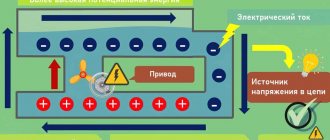
To supply electricity to an outlet, it must be generated somehow. To generate electricity, technologies from the late 19th century are still mostly used - electromagnetic induction, which converts mechanical energy into electrical energy. In other words, generators. The difference between generators is only in how mechanical energy is supplied. Previously, these were bulky steam engines. Over time, hydraulic turbines for running water (hydroelectric power stations), internal combustion engines, and nuclear reactors were added.
The operating principle of the generator is based on magnetic induction. The rotational movement of the generator is converted into electric current. That is, we can say that a generator is the same electric motor, but of reverse action. If voltage is applied to the electric motor, it will begin to rotate. The generator works in reverse. The rotational movement of the generator shaft is converted into electric current. Therefore, in order to rotate the generator shaft, we will need some kind of external energy. It could be steam that spins the turbine, which in turn spins the generator shaft
Operating principle of thermal power plants
It will be interesting➡ Total resistance
or it can be the force of the water flow, which, with the help of a hydraulic turbine, spins the generator shaft, and it, in turn, also generates electric current
Operating principle of hydroelectric power station
Well, or it could even be a windmill
Wind power plant
In short, the principle is the same everywhere.
By the way, a nuclear reactor is not capable of generating energy on its own. In fact, a nuclear power plant is the same primitive steam boiler, where the working fluid is ordinary steam. Yes, today there are other ways to generate electricity, such as the same solar cells, beta-galvanic and isotope nuclear batteries, “mythical” tokomaks. However, the above-mentioned “high-tech” has significant limitations - the prohibitive cost of materials, installation and setup, dimensions and low efficiency. Therefore, it is not worth seriously considering all this as a full-fledged high-power power plant (at least in the next couple of decades).
Varieties
There are two types: constant and variable. The first is in electrostatic types of circuits and those that have direct current. Variable occurs where there is sinusoidal energy. It is important that sinusoidal energy is divided into effective, instantaneous and average rectified. The unit of measurement for electric current voltage is volt.
It is also worth noting that the amount of energy between the phases is called the linear phase, and the indicator of the ground and phase current is called the phase current. A similar rule is used in all overhead lines. On the territory of the Russian Federation, the standard household electrical network is 380 volts, and the phase network is 220 volts.
Main varieties
Constant pressure
Constant is the difference between electrical potentials, at which the same value remains the same with polarity changes over a specific period. The main advantage of constant energy is the fact that there is no reactive power. This means that all the power that is generated by the generator is consumed by the load, excluding wire losses. Flows throughout the entire conductor cross-section.
As for the disadvantages, there is the difficulty of increasing with decreasing energy, that is, at the moment of converting it due to the design of the converters and the lack of powerful semiconductor switches. In addition, it is difficult to decouple high and low energy.
Note! Constant energy is used in electronic circuits, galvanic cells, batteries, electrolysis plants, welding tools, inverter converters and many other devices.
D.C
AC voltage
An alternating current is a current that changes in magnitude and direction periodically, but at the same time maintains its direction in an electrical circuit unchanged. It is often called sinusoidal. One direction in which energy moves is called positive, and the other is called negative. Therefore, the resulting quantity is called positive and negative. This exponent is an algebraic quantity. In answer to the question of what the unit of voltage is called, it should be noted that it is a volt. Its value is determined by direction. The maximum value is amplitude. It happens:
- two-phase;
Two-phase
- three-phase;
Three-phase
- multiphase.
Multiphase
It is actively used in industry, at a power station, at a transformer substation and is transmitted to every home using electrical transmission lines. Mostly three phases are used for connection. This type of electrification is common on many railways.
Note! It is worth noting that there are also some types of dual-system electric locomotives, which operate in many cases at a variable rate.
Alternating current
Excursion into history
So, the generator at our power plant converts mechanical energy into electrical energy. What's next? In what form and how exactly to transfer energy to the consumer? How to avoid colossal transmission losses?
Amazingly, such a situation actually existed! In the Russian Empire, until the beginning of the 20th century, there was complete confusion. A separate power plant was built next to each “large” consumer of electricity (a factory, the farmstead of a successful merchant, or a hotel for people of noble blood). There were many competing companies providing electrification services and, subsequently, their own electrical equipment tailored only for their network. Each electricity supplier set its own power grid parameters - voltage, frequency. There were even DC power grids! A person who bought, for example, light bulbs from the Lodygin and Co. Electric Lighting Partnership could only use them in the electrical network of the same company. If connected to the General Electric network, this light bulb would immediately fail - the network voltage of this company was significantly higher than necessary, not to mention other parameters.
Only in 1913 did imperial engineers decide to transmit electricity over long distances via overhead wire lines, eliminating the need to build power plants “at every outlet.” On the eve of the coming great war and the surge of patriotism, the authorities began to think about import substitution. Well, just like in our time, after the 2014 crisis). Many small Western firms (except German and French) were financially and legally suppressed; preferences and benefits were given only to domestic partnerships and enterprises. As a result, this led to monopoly in the electricity supplier market and, unwittingly, standardization of electrical network parameters.
Since Berlin and Paris were already electrified by a single power grid with 220 volt alternating voltage, domestic companies also adopted this standard. It was more convenient for people to use electrical appliances of a single type, without worrying that their newfangled electric vacuum cleaner would burn out at a new place of residence due to other parameters of the power grid. There was a complete displacement of many small firms - no one wanted to use their services and their devices, although they were forced to adapt to a single standard of the electrical network. Those same 220 volts AC.
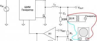
How and why to evaluate the quality of voltage in the network?
Really, why? After all, all you have to do is press a button on the TV remote control or plug your iPhone charger into a power outlet and enjoy the benefits of electrification throughout the country!
But there are times when something goes wrong: the crocodile is not caught, the iPhone does not charge, the air conditioner produces a strained hum instead of coolness, and the TV shows no signs of life after a click.
Knowledgeable people have gathered here who understand that the values of the main parameters of the electrical network - voltage and frequency - can be found out primarily using a multimeter. But what to do if you need to see what is happening in the outlet during the day? But what if you need to track a voltage surge that is much shorter in time than the multimeter measurement interval? Moreover, it may be that the time of appearance of this artifact is unknown.
Usually, for any voltage problems, stabilizers are installed, but they do not always help. After all, the stabilizer eliminates the effect, but not the cause of the problem. And if there is an abrupt short-term change in voltage, then the stabilizer will not only not help, but will also worsen the situation.
And in order to understand what to do in this or that case - check the quality of the contacts at the input or install a stabilizer - you need a Power Quality Analyzer.
A power quality analyzer provides a complete picture of what is happening at the outlet.
It will be interesting➡ Loop current method for calculating electrical circuits
In my work I use the HIOKI 3197 electrical energy quality analyzer, photos of which will be given in the article.
Without a quality analyzer, it is often completely unclear what is happening in the network: what kind of interference, surge voltages and dips, power factor cos, and so on. You have to act at random, using your experience and experiments. And with the Japanese HIOKI from Nagano everything is clear. In order to get a complete picture of what is happening in the network, the device has clamps for measuring current and clamps for measuring voltage, as well as a clamp for connecting to the neutral. Total - 7 connection points.
Power Quality Analyzer
A real case when you can’t do without a quality analyzer. The controller in the production line periodically froze and generated errors. When everything was shoveled, but the cause was not found, a power quality analyzer came to the rescue. After a short observation of the 220 V voltage supplied to the controller, it turned out that the reason was poor contact inside the surge protector.
Electrical voltage standards according to GOST
The regulatory document defines several indicators that allow characterizing the quality of electricity at connection points (input into consumer networks). We list the most significant parameters and give the permissible deviation ranges for each of them:
- For a steady-state voltage deviation no more than 5.0% of the nominal value (permissible norm) for a long time period and up to 10% for a short-term anomaly (maximum permissible norm). Please note that these indicators must be specified in the contract for the provision of services, and these standards must comply with current standards. For example, for household networks (220 V) it should be in the range of 198.0-220.0 V, and for three-phase (0.40 kV) - no less than 360.0 V and no more than 440 Volts.
- Voltage drops, such deviations are characterized by the amplitude, duration and frequency of intervals. The normally permissible amplitude range should not exceed 10.0% of the norm. Changes also include the flicker dose (flickering of light due to voltage changes, causing fatigue), this parameter is measured by a special device (flickometer). The permissible short-term dose is 1.38, long-term - 1.
Example of established voltage deviation and fluctuation - Throws and failures. The first include short-term increases in voltage amplitude exceeding 1.10 nominal. The second phenomenon means a decrease in amplitude by more than 0.9 from normal, followed by a return to normal parameters. Due to the nature of the processes, these deviations are not standardized. If this occurs frequently, it is recommended to install a voltage limiter (to protect against surges) and a UPS (for frequent dips).
- Overvoltage of the electrical network, this definition means an excess of the nominal value by more than 10% lasting more than 10 milliseconds.
Examples of overvoltage and sag (A), surges (B) - Voltage imbalance. The permissible deviation of the asymmetry coefficient from the norm is 2.0%, the maximum is 4.0%.
- Non-sinusoidal voltage. It is determined by calculating the distortion coefficient, after which the resulting value is compared with standard values.
Example of voltage sinusoidality violation - Frequency deviations. According to current requirements, the normally permissible deviation of this parameter is 0.20 Hz, the maximum permissible is 0.40 Hz.
What is it measured in?
The unit of voltage is called the volt (V). One Volt is expressed as the potential difference between two points of the electric field, the forces of which perform 1 J of work to move a charge of 1 C from the first point to the second. The voltage is measured with a special device - a voltmeter.
Orlov Anatoly Vladimirovich
Head of the Relay Protection and Automation Service of Novgorod Electric Networks
Thus, a value of 220 V implies that the electric field of a given network is capable of doing work (expending energy) of 220 J to “pull” charges through the circuit and load.
Known voltage ratings
All long-distance power transmission lines operating today operate at rated voltages of 115–1200 kV three-phase current. Further increase in voltage is ineffective and leads to the appearance of abundant corona discharges, which tend to develop into an arc. The largest losses occur in the low-voltage part. For example, in France, annual losses are estimated at 325 GW hours, which is 2.5%, in the USA they reach 7.5%. This is explained by the difference in rated voltage - 220 V versus 110.
In 1980, the cost-effective length of the line was 7,000 km, but the actual ones are much shorter than this figure. At significant distances, capacitive and inductive reactance begin to play a role. Together they form a reactive impedance that prevents energy from being supplied to users. These are currents wandering here and there, representing a completely parasitic effect. This determines the line power factor, which is not too large.
Today it has been proven that it is more profitable to supply direct current over long distances that does not flow into inductive resistances - capacitive, formed by the wire and ground, and inductive. There is no concept of reactive power. The fact is proven that Nikola Tesla fought for alternating current mainly to cause damage to Edison.
Taking into account the savings, it is profitable to build converter stations at the ends of powerful lines to transfer currents. At the same time, losses due to radiation and leakage through the screen into the ground are reduced, and the level of corona discharge is reduced. Already today, cables for recharging submarine batteries are powered by direct current; it is impractical to transmit alternating current through them even at a distance of 30 km. Today's lines are 20 times longer and are successfully operated. For AC transmission, restrictions depend on distance:
- On small lines there are heat losses, designed not to destroy the wire insulation.
- At medium distances, the voltage drop is taken into account; you cannot take it too high.
- At long distances, reactive power factors come into force, determining the stability of the system.
From the history of the issue
The history of the development of transmission lines is briefly discussed in the review of two-pole circuit breakers, but let’s try to “take a look around Europe” so that readers can understand the reasons for the need to divide equipment into voltage classes. Gramma was the first in history to transmit direct current from a dynamo. The inventor of the said equipment sent a current three-quarters of a mile away. This happened at the Vienna Exhibition in 1873. Previously, there was already a telegraph (with lines up to 20 km), but it was powered by galvanic elements or from a static generator, which has little to do with the topic.
Then there was no need to transmit current over long distances. Used from local generators. For example, to power lighthouses in England and France. All of them rectified the current, as if on purpose, copying modern high-voltage HVDC lines. A new significant event occurred in 1882, when Oscar von Miller hired the Frenchman Marcel Despres to transmit a voltage of 2 kV over a distance of about 60 km. This has already become a clear achievement, but a quarter of the original potential difference reached the addressee.
Then a conflict occurred between Edison and Tesla, which ended at the end of the 80s with the creation of new equipment designed for alternating current. Dolivo-Dobrovolsky kept his nose to the wind, and immediately developed a three-phase engine power system. The Russian was not given a patent due to counterarguments from Nikola Tesla, but the battle of currents led to the observation: “The use of a transformer can significantly reduce line losses.”
Which turned out to be immediately used. In 1891, a voltage of 15 kV was transmitted over as much as 180 km with an efficiency of 75%. Edison is resting! From this time on, the advantages of alternating current became obvious; low voltage caused high losses in the line. This is the main reason why in the modern world there is a need to divide equipment into voltage classes.
Already in 1912, the voltage reached 110 kV, ten years later it was 220. The rate of voltage growth showed an exponential dependence on the passing years. Then lines for 380, 765 (750) and 1200 kV were constructed.
Mains voltage parameters in Russia
Electricity producers generate alternating current at industrial frequency (50 Hz in Russia). In the vast majority of cases, three-phase current is transmitted along power lines, increased to high and ultra-high electrical voltage using transformer substations that are located next to power plants.
According to the interstate standard GOST 29322-2014 (IEC 60038:2009), the mains voltage should be 230 V ± 10% at a frequency of 50 ± 0.2 Hz [1] (phase-to-phase voltage 400, phase-neutral voltage 230 V, four-wire circuit " star"), note "a)" of the standard states: "However, 220/380 V and 240/415 V systems are still in use."
Four-wire connections (three phase wires and one neutral (neutral) wire) are supplied to residential buildings (rural streets).
power lines (overhead or cable power lines) with a phase-to-phase voltage of 400 Volts. Input machines and electricity consumption meters are usually three-phase. A phase wire, a neutral wire and, possibly, a protective grounding or grounding wire are supplied to a single-phase socket; the electrical voltage between the “phase” and “zero” is 230 Volts.
The rules for electrical installations (PUE-7) continue to include the value 220
but in fact, the voltage in the network is almost always higher than this value and reaches 230-240 V, varying from 190 to 250 V.
Differences by voltage classes
Using the example of power lines, the difference in design by voltage class is demonstrated. At the same time, operational features arise - protection measures, repair and construction techniques. Each case has specific requirements. You should not be surprised if the wires are divided into voltage classes in one order, and insulators and lightning protection cables - in another.
It is obvious that climatic conditions impose certain requirements, and physical processes – others. Exactly the same is said about electrical equipment, where the division into voltage classes differs.
Currently in effect, since 2014.
But in Japan and on the American continent there is no less, and (in 39 countries) the standard voltage ranges from 100 to 127 volts.
Brazil stands out especially, in the northern regions of which the standard voltage is 127 volts, and in the rest - 220. In Japan, with a standard voltage of 110 volts, the network frequency can vary from 50 to 60 Hz.
The main solution for high-quality power supply is voltage stabilizers.
Unfortunately, emergency situations in the electrical networks of our homeland are quite frequent, and the consequences of voltage changes in our homes lead to the failure of expensive electrical appliances, the cost of which far exceeds the prices of voltage stabilizers and the prices of surge protection devices.
Modern technologies make it possible to ensure uninterrupted power supply with the specified parameters; one of such devices that can help is the HIDEN UPS, an even more advanced ECOVOLT UPS.
It will be interesting➡ What is static electricity and how to get rid of it. What causes static electricity?
Amount of permissible voltage drop: PUE
According to the accepted rules for the design of electrical installations (PUE) back in the former USSR, a voltage drop is the difference in voltage levels at different points of the network. As a rule, these are the starting and ending points of the chain. In established standards, the law requires a distinction between the concepts of voltage deviation and voltage loss. If the first case, on a generally accepted scale, is considered using the example of an incandescent lamp, the deviation indicator of which is recognized as nominal and mandatory, then in the case of the loss considered on the station buses, this is recognized as a recommended indicator.
Normal voltage drop in the network:
- In so-called overhead lines – up to 8%;
- In cable power supply lines – up to 6%;
- In networks of 220 V - 380 V - in the region of 4-6%.
In this case, a drop in the emergency mode is considered to be a drop of up to 12% in the network - this is the established limit. A fall above the established norm promises the activation of the automatic protective system, which should be activated when the lower norm is reached for at least 30 seconds.
Also in some sources you can find voltage standards that exceed even the new indicators of 230 V and 400 V. Do not confuse examples of domestic use with a plant or factory, where the indicators naturally significantly exceed the domestic environment.
How much do you need for electrical appliances?
Equipment manufactured in Russia for domestic consumers operates at both 220 V and 230 V, because manufacturers provide the required margin from -15% to +10%. from face value. But in each specific case, the permissible range of power supply characteristics for the device is indicated in the product passport or on its label. For example, computers can operate at 140 - 240 V, and a telephone charger at 110 - 250 V. These markings are often applied to the product itself.
Devices with electric motors are most sensitive to power quality. Here, a reduced voltage can lead to difficulties in starting and shortening the service life of the equipment, while an increased voltage will lead to overloads, which also shorten the service life. If you take a regular incandescent lamp and lower the supply voltage by 10%, the glow intensity will noticeably decrease, and if you increase it, its service life will be reduced by 4 times.
The permissible maximum network limit is 253 V. This value may be too high for electrical equipment designed for 220 volts. The difference in voltage will lead to overheating of power supplies, network adapters, and premature failure of devices.
If you notice that your equipment has begun to overheat or break down, check the voltage in the network. If a deviation of more than 10% is detected, immediately contact your network company. They are required to take measures to eliminate the factors that caused the violations.
Now you know what the voltage standard in the Russian network is according to GOST. If you have any questions, ask comments under the article. We hope the information was useful and interesting for you!
Deviation from rated voltage in the private sector
- Burnout of the neutral working conductor in a transformer substation
- Unbalanced load on power lines. Basically, there are 3 phases running along the street and power engineers try to evenly distribute the load among the phases. It often happens that this was done a long time ago and is not true. As a result, it turns out that one phase is overloaded and a voltage drop occurs, maybe 190 V or 180 V, but nevertheless this does not correspond to the norm.
- A neighbor's welding work may affect the voltage
- Lightning strike
Reference Information. If the house is located near a transformer substation, then the voltage may be close to 230 V or more, but this is within normal limits. Power engineers do this on purpose so that there is no strong voltage drop at the end of the line.
Remember! Switching and protective equipment (batch switch, circuit breaker, RCD) does not protect the electrical network from voltage surges.
Maximum voltage deviation in the electrical network
The current in the network is, for natural reasons, not constant and varies in certain parameters. Within the framework of the new 230 V/400 V standard, the nominal deviation is permissible within 5% and a maximum of no more than 10% should be observed in short-term intervals. Thus, such a theoretical deviation is allowed within 198 V and up to 242 V. This range can be considered relevant for most current apartments.
What affects network fluctuations in energy supply and voltage loss:
- One of the most common reasons is obsolescence of equipment, including meters, electrical panels, wiring cables, and so on;
- Significant errors are also observed in a poorly maintained network;
- Errors when planning and performing installation work in the house;
- Significant increase in energy consumption indicators exceeding the established standard.
As already noted, network fluctuations of +-5% are acceptable. So, for example, according to the supplied indicator of 220 volts, the permissible deviation in the network is equal to 209 V and the maximum excess is equal to 231 V.
Voltage parameters
Before you say that the voltage in your network does not meet the standard and file a claim with the energy supply organization, you need to know this standard. The voltage deviation range is set in normal mode: δUynorm= ± 5%, in the maximum permissible: δUylim= ± 10% of the nominal value.
In Russia, the rated voltage of the household network is Unom = 230 Volts (V), the upper range is 242 V. For Unom = 380 V, the upper range is 418 V. If the voltage is higher than these ranges and for this reason household appliances fail, you have the right to complain to the energy supply organization.
Real voltage measurement examples
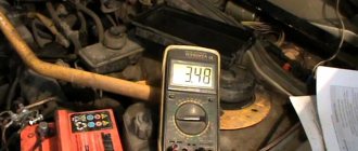
The simplest example of measuring voltage at home is a AA battery. In it you need to attach the black probe to the “–” terminal and the red one to the “+” terminal, set the switch position to 2 V DC voltage.
Example of measuring voltage on a battery
If the readings for a 1.5 V battery are in the range from 1.6 to 1.2 V, then such a power source is considered suitable for all equipment; if the values reduce to 1 - 0.7 V, pulsed devices will be started from the battery, for example, a watch. If the voltmeter shows 0.6 V or less, the discharge has reached a critical value.
When measuring the potential difference in a household network, you should touch the contacts of the socket with the probes. Since the insulated part of the probe has a restrictive ring behind which there is a long rod, you can safely reach into the outlet without the risk of touching live parts. Deviations from the nominal value by 10% are considered acceptable, that is, from 198 to 142 V.
You can also measure the potential difference at the output of a car battery or at another element of the electrical wiring circuit. To do this, the black probe of the multimeter is installed on the “–” terminal of the battery, and the red one on the “+” terminal.
If the battery is charged, then the voltmeter readings should be in the range from 12 to 14 V, but there are models with a large spread. This measurement allows you to diagnose various causes of problems.