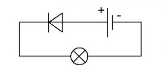
The device presented here is a zener diode for testing the voltage value of an unknown zener diode. A zener diode is an electronic component that maintains a constant voltage across its contacts, and the source voltage Vs must be greater than the zener diode's own voltage Vz , and the current is limited by a resistance Rs , so that its current value was always less than its maximum power.
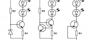
Diagram of the simplest method for checking zener diode voltage
Radio amateurs and all those who are good friends with electronics know that the task of finding a zener diode with the required characteristics (operating voltage) is boring and painstaking. It happens that you need to go through a lot of different instances until you find the desired Vz value. Checking the status of the zener diode is usually done using a regular multimeter diode scale, this test gives us an accurate idea of the condition of the component, but does not allow us to determine the Vz value. In general, a zener diode tester is a really convenient device when we want to quickly find out the value of the voltage Vz.
Automatic LED tester SID GJ2C
The most common malfunction of LED TVs is the presence of sound but no picture. The reason is overcooling of the LED bulbs in the backlight. For the equipment repairer, the GJ2C SID saves inspection time by automatically selecting parameters. It can also be used to test LED strips and lamps in any lighting fixture.
Key Features:
- weight 87 g;
- 3-digit display, not foldable.
- output voltage 0-300V
- dimensions 100 x 59 x 32 mm
- input voltage 85-265V;
GJ2C SID tester intelligently regulates current and voltage, suitable for AC and DC current. The main area of application is the repair of backlit TVs of any size. The device is equipped with double protection and does not damage the LEDs due to independent selection of parameters and smooth start-up.
Advantages of SID GJ2C:
- high measurement accuracy;
- does not shake when touching the test leads.
- comparison of theoretical indicators with real ones;
- possibility of use not only for LED lamps, but also for voltage regulators;
After connecting the power, it takes 10-15 seconds to warm up. When you touch the element being tested, the voltage first goes to zero, then gradually increases. The performance of the part is determined immediately; you need to wait about 2 minutes for the exact parameters due to the inertia (passivity) of the screen.
Attention! In addition to LEDs, this device can control zener diodes and other driver elements.
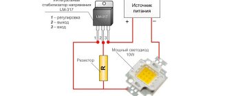
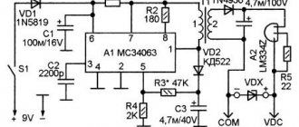
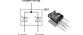
Diagram of a device for testing zener diodes
As you can see, the scheme is simple. The voltage from the transformer with two 24V secondary windings is rectified and filtered to obtain a constant voltage of about 80V, then goes to a voltage stabilizer formed by the elements (R1, R2, D1, D2 and Q1), which reduces the voltage to 52V to avoid exceeding the maximum operating voltage limit of the LM317AHV .
Pay attention to the letter index of the microcircuit. For LM317AHV, the input voltage, unlike LM317T , can reach a maximum of 57V.
The LM317AHV contains a DC generator, where a switch (S2) is added along with a resistor (R4) to select two test modes (5 mA and 15 mA) as the current source for the zener diode under test.
This tester is easy to assemble from standard components. A ready-made switching power supply from some DVD or satellite system tuner, and a voltmeter either in the form of an industrial module on a microcontroller, or take a D-830 multimeter.
- REPAIRING A PHONE THAT WILL NOT CHARGE
- CABLE LOOP TESTER
- CIRCUIT REPAIR: DISASSEMBLY-INSTALLATION, SELECTION OF ANALOGUES
DIY crafts for car enthusiasts
Radio amateurs sometimes face the problem of checking unmarked zener diodes. Naturally, there are many ways, for example, a laboratory power supply with a current limiting function, etc., but many use homemade adjustable voltage stabilizers without a current limiting function, or the power supply has a current protection function rather than stabilization. It was decided to build a simple stand-alone tester that can check the stabilization voltage of zener diodes. For these purposes, ready-made modules purchased from Chinese online stores were used. 1) Boost DC-DC voltage converter based on the MT3608 chip. Such converters are quite popular and cost a penny; they can provide an output voltage of 28-30 Volts.
2) Board for charging LI-ION batteries from USB. The board is essentially an automatic charger for one can of Li-Ion battery, providing a maximum charging current of up to 1 Ampere.
3) Lithium-ion battery of any standard, capacity also does not play a particularly big role.
4) Digital Volt-Ammeter for voltage 30 Volts
5) Socket for DIP chips, such sockets are designed for solderless installation; a zener diode will be inserted here, which needs to be tested.
These are the main components, the rest is minor stuff.
As a case for this design, a case from a cheap power bank for a dollar was used.
Due to limited space in the case, I used 1.2 volt nickel-metal hydride batteries connected in series. In this case, you don’t have to install a specialized charging board, since nickel batteries are not as critical to charging as lithium ones.
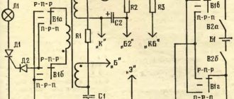
The design diagram is now in front of you.
Initially, we take the DC-DC converter board and rotate the trimming resistor until we get the maximum possible voltage at the output. Based on this, it becomes clear that our tester can test zener diodes with a stabilization voltage of no more than 28-30 Volts. The limiting resistor is designed to limit the current through the zener diode; if it is not installed, the experimental zener diode will burn out.
The electrolytic capacitor at the output of the board is designed to smooth out ripples from the converter; this is necessary to avoid false voltmeter readings, since the output of such boards has quite large ripples. The switch, I think it’s clear what it’s intended for, can be replaced with a button of any power.
Taking into account the fact that such a tester will work for a short time, the battery charge will last for a very long time, so if desired, the power source can be replaced with a 6F22 standard battery (a regular 9-volt battery).
Author; AKA KASYAN
Popular;
- Power supply with voltage and current regulation
- Charger made from Soviet parts for batteries
- Voltage converter +U to -U on CD4049 microcircuit, circuit.
- A simple laboratory power supply made from an old computer power supply.
- Powerful charger for any battery
- Simple voltage stabilizer for the charger
- Simple voltage regulator on LM317, circuit
- Boost converter, DIY circuit
Main conclusions
Owning a multimeter with your own hands is simple, but it can be useful for a home craftsman who often has to check the serviceability of lamps and LED strips. A device based on the LM317L chip can be made by a radio amateur who regularly tests diodes. In some situations, this may be more useful than a store-bought device.
On TVs, light bulbs often fail due to defects or setting the picture to maximum brightness, which increases the voltage. Repairing a TV is a difficult task, and it is not recommended to do this work yourself if you do not have the knowledge, experience or tools. Everything is done much better by a trained television technician.
LED tester with LCD display
There are 2 types of testers: analog and digital, the latter have more functionality and measurement accuracy. They are equipped with an LCD display, measurement parameters are selected automatically, test results are displayed clearly and do not require knowledge of converting one value to another.
An LCD tester has a more complex design because the circuit includes integrated circuits, diodes, transistors and resistors, which are connected on a common substrate.
Scope of application of meters with LCD display:
- determining the presence of electric current in the wiring;
- calculation of the range of parameter changes;
- short circuit indication;
- measurement of capacitance, inductance, electric current, capacitor temperature;
- contact status;
- measurement of electrical parameters in washing machines, computers, televisions, car networks, power tools.
- determining the current flowing through the LED;
- determination of the voltage drop across the pn junction;
Users value LCD devices for their ease of use and affordable price.
Checking the LED with a multimeter tester for serviceability
No tools other than a standard digital multimeter are required to test functionality. The easiest way is to use sensors that allow you to control elements with any number of cables in any project. After installing the bell device, you must touch the red probe on the anode and the black probe on the cathode. The working diode lights up, after changing the polarity, the number “1” appears on the screen.
The glare during testing is small, in good lighting it is not visible at all. If the LED element is multi-colored, you need to determine the pinout so that you don't have to run cables randomly during the test.
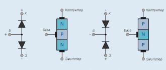
Most multimeters have transistor test jacks that can be used to test diodes. By design, these are 8 holes at the bottom (4 for PNP transistors and 4 for NPN transistors). To test LEDs in PNP, the anode is inserted into slot “E” and the cathode into slot “C”. If the diode is working, it lights up. When testing in NPN, the polarity is reversed.
Important! The disadvantage of this method is that it is impossible to control elements with solder residue without long legs.
The driver is required for testing high-power SMDs. A multimeter is connected in series to it, the current changes are visible on the screen. If the product is of poor quality, the indicator gradually increases. The voltage drop is measured by connecting a multimeter in parallel. To determine whether the LED element is suitable for further use, the obtained indicators are compared with the data from the technical documentation.
If the LED is infrared, with the correct position of the anode and cathode, the number 1000 is displayed on the screen, changing the polarity, the number 1 is visible.
The main causes of malfunction and failure of LEDs
A special feature of LEDs is the reverse voltage, which is only a few volts higher than the drop. The LED does not work if even the slightest error is made during connection. Super-bright diodes in the backlight burn out during voltage surges. In this regard, 220 and 12 V lamps are more stable. About 2% of LED products have defects; it is recommended to check them before installation.
Where is the voltage indicator?
Understanding how the line voltage is divided between two capacitors in series is critical to figuring out how a capacitance indicator works.
Let's return to the theory of electrical circuits. In a series circuit, the voltage will be distributed according to the resistance value (Ohm's law). For a capacitor, the smaller its capacitance, the greater the so-called capacitive resistance to alternating current. Thus, when two capacitors are connected in series, the largest fraction of the voltage applied to them will be dropped across the smaller device.
In the example above, only a few volts are between your feet and the floor (at the larger capacitance), and the rest of the 220V is applied between your head and the light bulb filament (at the smaller capacitance). Now, if you hold your thumb on the contact pad at the end of the capacitive indicator handle and touch it to the bare section of the wire powering the lamp, then instead of a small capacitance, a voltage indicator circuit that is sensitive to low currents is included in the capacitive current flow circuit. This current, of course, increases, but a high-resistance resistor inside the indicator limits it to a non-hazardous value. As a result of the flow of current, a neon lamp or LED lights up in the indicator or a buzzer sounds.
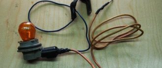
Making your own probe
It is difficult to ring a small LED with a standard probe, so for comfortable use of the multimeter you can make it yourself. Several elements are used for this.
Sewing needle
You will need:
- housings from black and red handles for handles;
- plugs and cable;
- steel sewing needles 35-45 mm in length and 0.8-1 mm in diameter;
- scraps of copper wire (pair - 250-300 mm long and pair - 120-150 mm long);
- rosin or alcohol rosin.
The manufacturing process is carried out in stages:
- The wire is cut and tinned with solder.
- The needles are tinned with solder so that there is 8-10 mm left to the sharp parts.
- Conductors 0.3-05 mm in diameter are attached next to the ears of the needles, and then wound in turns to the tinned area.
- The winding is covered with solder.
- The tinned cable is bent in half around a screwdriver. The free sections are fastened together in a pigtail. The resulting loop is bent at an angle.
- The conductors are attached to the needles with a soldering iron.
- Plaque is removed from all joints using alcohol.
- A thread is wound in the center of the needles until bulges appear. They will need to be coated with Moment glue and inserted into the tips of the handle bodies, fixing them as evenly as possible.
- After the glue has dried, epoxy is poured into the cavities, which hardens for 24 hours.
- The ends of the probes are tinned and soldered to the plugs.
- To protect the shell from friction, problem areas are placed in a heat-shrink tube.
- Flexible conductors are made of red and black copper wires 1 m long.
- Tips with needles are connected to flexible conductors with a soldering iron. The handle pieces are fastened together.
The optimal wire cross-section is 1.3 mm2.
Plug
Dismountable plug
You will need:
- Soviet electrical plug with brass pins;
- old multimeter probes;
- plastic tube;
- wire with thick copper cores;
- banana plugs.
Making a probe from a plug
Progress:
- Removing the pins from the plug by unscrewing the top bolt.
- Removing the base from old probes - the pins can be removed with pliers.
- Separating the bent part of the pins with a file and turning them so that they fit with force into a piece of plastic pipe.
- Separating and stripping speaker wire.
- Tinning of cable ends and pin ends at soldering points.
- Inserting a wire into the base of the old multimeter leads and soldering a brass plug to it.
- Pulling the cable back and fixing the area where it enters the tube with heat shrink.
The second end of the wire is threaded into the connector. The cable will need to be secured with a bolt to ensure secure fixation.
Pin from laser CD drive
Laser drive pin
You will need:
- steel pin with sharp tips;
- heat-shrinkable tubes of different sizes;
- two markers (black and red);
- tube according to the size of the pin;
- copper wires designed to operate in a network with a voltage of 300 V.
Dividing the stud into 2 parts
The procedure for making the probe:
- The hairpin is cut into 2 parts. The sawn edges are covered with flux.
- The ends of the wires are protected by 5 mm and tinned.
- Tin-plated wires are attached to the sawn sections - one for each.
- Thermal tubes are put on and seated on the structure.
- The handles of the probes are made from felt-tip pens - just cut off 5-7 cm from the beginning.
- Pins with soldered wires are inserted into pieces of felt-tip pens so that the tips protrude from the felt-tip pen.
- The elements are fixed with epoxy.
- After drying, the handle is installed in a colored tube with heat shrink.
- The plugs are made from pieces of brass pipe from the antenna, 3 cm long.
- A brass tube is inserted into the connector, and a plastic tube is adjusted to it.
- The remaining ends are soldered onto brass tubes and wrapped with electrical tape so that they fit the diameter of the plastic ones.
- Pieces of thermal tubes 4 cm long are put on the plugs and seated.
Device for testing LED backlighting of TVs and individual LEDs
If you need to work with LED TVs, you should not give preference to a simple multimeter. It only allows you to determine the serviceability of the LED elements, and the illumination is poorly visible. A special device is required, for example SID GJ2C. Home craftsmen use homemade products if the functionality or price of the devices offered in stores do not suit them.
The simplest option is a power source from a phone charger with a voltage of 3.3 V and 300 mA. It is suitable if you need to test the functionality of individual diodes with an electric current of up to 3 mA. To expand the functionality, other circuits are required.