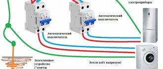
Grounding is the intentional creation of contact between an electrical device connected to the electrical network and a grounding device. It is designed to divert current in the event of a break in the housing, which appears on the metal parts of household appliances when an accident occurs. Grounding automatically cuts off the voltage due to the operation of an RCD (residual current device).
When the equipment is protected in this way, then in the event of any human contact with household appliances, the current remaining on the equipment will no longer be dangerous. If the equipment was not grounded during installation, the current passes through the body of the person who touches it. Although this residual tension will be noticeable, it will not be dangerous.
Residual tension is noticeable, but not dangerous. Source yandex.ru
What is the difference between “zero” and “ground” in electrical engineering?
Some electricians with experience cannot always answer correctly the question “what will happen if the ground is used instead of zero” or what is the difference between grounding and grounding. It is important to understand this in order to avoid mistakes in your work.
If grounding is done, the body of the equipment is connected to the neutral conductor. When grounding is done, the body of the electrical device is connected to a grounded circuit consisting of metal pins driven into the ground.
Grounded circuit - metal pins driven into the ground Source yandex.ru
Characteristics of the plus and minus wires
If an electrical cable has 2 conductors, then one of them is “plus” (phase), and the second is “minus” (zero). It is imperative to know the polarity when connecting an electrical appliance, otherwise there is a risk of damage to the equipment.
Important! Most often, “plus” and “minus” are marked with letters, symbols or a specific color provided by GOST.
Marking in Latin letters
In electrical circuit diagrams, the phase (“plus”) is marked with the Latin letter L; the same marking is used on wires if there is no color difference. The Latin letter N means “zero” or “minus”. Grounding is marked as PE or PEN.
Sometimes, when working with wiring that does not have any identification marks, they use markers that are placed on the wires in the form of colored rings with marks. Another marking option could be shrink tape of different colors. It is put on a cable of the appropriate voltage and, to secure it to the carrier, is heated.
Connected earth instead of zero: risks and consequences of error
If the socket is grounded instead of grounding, if there is an RCD in the electrical circuit, it will knock it out. If there is no protective device, a potential is created that is dangerous for other consumers if their earth conductor is connected to yours.
It is important to know! Your devices may still continue to function, and most likely you will not feel the difference, especially when the grounding is done well.
Other problems when the “protective zero” in the electrical panel breaks:
- This is an illegal connection to the network (bypassing the electricity meter).
- Equipment, including neighbors' equipment, may burn out.
- When connecting household appliances to the socket of a damaged line, all grounding contacts will be energized.
Voltage on the body of a household appliance Source kupisantehniky.ru
Determination methods
There are several ways to distinguish “zero” from “ground”.
Wire color coding
Professional and conscientious electricians will never install wiring without observing color coding. Provided that the installation was carried out in compliance with the basic rules of the Electrical Installation Code, each conductor has a specific color depending on the function performed:
- The blue/light blue sheath is used to mark the neutral conductor.
- The yellow-green sheath (stripes) is used to indicate the grounding conductor.
- It is more difficult with a phase wire, since it can have a sheath of white, black, red, orange and other colors. Regardless of the chosen “phase” color, this installation will be correct.
Zero is marked in blue, ground in green-yellow, phase in red.
Remember: even if conductors of the corresponding colors have been discovered, by which “phase”, “zero” and “ground” can be determined, do not rush to conclusions. You can be completely confident in the correct installation only if you have done it yourself. In other situations, such a method of searching for “zero” and “ground” will be incorrect. So move on to the other methods.
Differential current
It is much easier to distinguish “zero” from “ground” if there is a residual current device (RCD) or differential circuit breaker in the serviced area. Use a lamp with wires, connect the device to a phase and one of two conductors. If the protection does not work, then the light bulb is connected correctly - to the phase-zero pair. If the RCD was triggered and the branch was de-energized, then the phase-ground pair was involved.
If the RCD does not work in both cases, then there may be problems with the functionality of the equipment. The performance of the differential protection device can be judged by the test performed. Any such equipment has a “Test” button. Click on it.
Note. The protective device may not operate for another reason: if the current flowing through the lamp is below the rated differential value (at which the equipment must de-energize the circuit). For example, an incandescent lamp passes a current of about 20-40 mA. If a 100 mA RCD is used, then it is logical that the device will not work.
Grounding contacts on sockets
This method is suitable for any facility that uses a two-pole input circuit breaker and grounding sockets. Turn off the machine, which ensures that there is no connection between zero and ground. Do the same with all household appliances. Take a multimeter, activate the “Test” mode and perform the procedure between the ground pin on the outlet and two unknown wires.
When the ground contact of the socket is connected to “zero”, the multimeter will show a huge resistance, with “ground” - close to zero value. This method will help ensure that the grounding outlets are connected correctly.
Using a Multimeter
Before checking live wires with a multimeter, you should clean the wiring. Do not forget about safety precautions and be sure to de-energize the electrical network at the facility being serviced.
If the electrical wiring does not have color/symbol markings or the installation was performed by an unknown technician, then use a multimeter. However, first use an indicator screwdriver to determine the “phase”. Set up the multimeter by selecting an AC voltage measuring range greater than 220 V. You can take any type of measuring device. The specific size of the range does not matter: the main thing is to set it above 220 V.
On the phase-ground pair the voltage will be less
Using a multimeter, connect the “phase” to one and then to the other conductor. On the phase-zero pair, the voltage value will not be much higher than on the phase-ground pair. This will allow you to distinguish “zero” from “ground”.
Note. Determining “ground” using a multimeter is relevant for older electrical networks built according to the TT configuration. For modern TN-CS topologies, the method is irrelevant. In the second case, the neutral and grounding conductors are separated inside the building, therefore they are electrically identical and interconnected. They have the same resistance, which means that when using a multimeter on both pairs there will be an equal potential difference.
A multimeter is not suitable for searching for a grounding conductor in a TN-S electrical network. “Zero” and “ground” are separated from the energy source to the consumer. Due to the different lengths of the wires, there will be a completely different resistance, which causes the resulting difference in voltage. It may turn out that the potential difference on the phase-ground pair will be higher than on the phase-zero pair.
Disconnecting the neutral wire (electrical panel)
Make sure that electrical appliances have been disconnected from the network, so that current is guaranteed not to flow to the neutral conductor. Look into the distribution panel, the location of which is regulated by the PUE rules, disconnect the neutral wire (unscrew the clamps, pull the cable out of the input circuit breaker and insulate it). Or remove the conductor from the neutral bus, which is used for further branching of the neutral. In an apartment or private house there will be two working conductors - grounding and phase.
Pick up the multimeter again, measure the voltage between the phase (determined with an indicator screwdriver) and the other two conductors. The voltage will appear exclusively between the “phase” and “ground”, since the neutral wire is disconnected from the panel.
Note. There is such a thing as “induced voltage”. Without going into details, we note that as a result, when measuring a phase-zero pair, the multimeter will show a voltage different from “0” (usually no more than 10 V).
Dialing method
Dialing is one of the most popular methods used by craftsmen to find places where electrical wiring is broken. It is suitable for determining "zero" and "ground". This method is relevant provided that you know the location of the neutral and grounding conductors at one end. For example, when the dialing is carried out from the distribution panel, but for some reason at the other end the wires have a different color marking (or the same color).
Perform a complete blackout. Dialing can be done with professional instruments (any multimeter model has a corresponding function) or with a conventional circuit consisting of a light bulb, battery and wires.
If the length of the measured conductors is short, then use a piece of cable, connecting the section to the ends of the section. If you need to ring the conductor running from the distribution panel to the socket in the back room, then it is better to use a known conductor: before turning off the power, use an indicator screwdriver to determine and mark the “phase” (at both ends).
Connect one probe of a multimeter (or a homemade device) to the marked phase wire, the other to one, and then to another unknown conductor. Move to the opposite end of the line. Connect the two ends of the unidentified cores alternately to the marked phase cable. Label them.
Video description
Grounding instead of zero in the socket. What will happen.
Therefore, deal with the absence of a “zero” in your electrical wiring. If the “working 0” going to the electrical outlet is damaged, find the location of the damage to the neutral circuit.
Instead of a damaged “zero”, you can use a ground wire. To do this, a new marking must be made:
- on the zero line;
- in sockets;
- in the electrical panel.
The oven and dishwasher must be connected to different groups. Each line must be equipped with a separate protective circuit breaker. An RCD can be installed as a common one for the entire electrical circuit.
The grounding conductor is also the same for everyone; it can be taken from another line.
But what if your house does not have protective grounding at all?
It is clear that when carrying out major repairs, electricians will replace the wiring in accordance with the Electrical Installation Rules. At a minimum, three independent wires will appear in your input panel: phase, working zero and protective ground. All that remains is to replace the wiring in the outlet network.
But major repairs can be carried out in a few years, and today you are already using a boiler and washing machine without grounding, or even worse - with a protective grounding. There is only one way out: organize grounding yourself. If you live in a private house, the technical side of the issue is significantly simplified. But for high-rise buildings, the cost and complexity of the work depends on the floor.
An alternative is to organize a grounding bus with your neighbors, with junction boxes on each staircase.
The tire must be one-piece until it is inserted into the ground. Near the foundation, preferably not in the road surface, but in a flower bed, a grounding loop is organized in accordance with the Electrical Installation Rules. Each resident of the entrance can connect to the common bus and bring “ground” into the apartment. Then there are two options:
- Organize a grounding contact group in the distribution panel, and replace all electrical wiring with three-wire wiring.
- Inside the baseboard, stretch the earth cable under each socket and insert it into the mounting boxes.
Either way, you will protect both your electrical appliances and, most importantly, your health.
Video description
Earth instead of zero.
TN
Exposed conductive parts are non-insulated areas of electrical installations that can be touched. During normal operation, no voltage is supplied to these areas of household electrical appliances. However, everything will be the other way around: if the insulation is destroyed, potential will appear on the body.
The causes of damage are mainly related to specific factors:
- aging technology;
- physical destruction;
- long service life at high speeds;
- accumulated dirt;
- humidity on the coating located near the body;
- climate influence;
- defect caused by the manufacturer.
Two connection schemes
The same zero break, but the consequences are so different
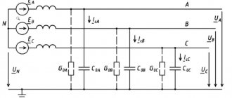
To understand the role of “Zero” and “Earth”, you need to delve a little into the essence of the methods of delivering electricity to end consumers and the differences between the latter.
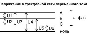
It should be mentioned that electrical systems can be linear and phase. Linear ones are used in the industrial field of activity, where increased power is required (380V), phase ones exist for use in everyday life (220V). In both cases, the connection diagrams use three wires. Only for linear (380) there is a phase in each of the three wires, and in the household version (220V) there is Phase, Zero and Ground.
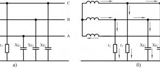
For security, each system uses its own connection schemes. We will not consider industrial networks, but household networks should be studied; two schemes are used here:
- TT – full grounding
- TN-CS – joint connection of ground and zero, after the power consumer
Connection diagrams used: 1. To zero, 2. To ground
To make it more clear, let's decipher the abbreviation:
- T – earth
- N – neutral
- S – separate, independent
- C – combine
- L – phase
- PE – protective
- PEN – united
These two schemes are used, but one more existing scheme, TN-C, should be pointed out - this is an old, but still valid system used in most “old” houses, which has the abbreviation PEN.
In it, Zero and Earth are combined (PEN) throughout. Such networks are not entirely safe, especially for electrical appliances. They were installed in Soviet times, few household appliances were used, and therefore the designers did not see the point in unnecessary spending on electrical wiring for the sake of a couple of dozen televisions (the loads were small) - 30% savings! At industrial enterprises, grounding was done separately.
Electrical network structure, main elements
It is known from a school physics course that if you rotate a permanent magnet around a winding on a coil in wires, an EMF (electromotive force) arises, which moves charged particles along the wires. This example explains well what phase and zero are in electricity.
An example of obtaining EMF and current in a metal conductor frame
Based on this principle, electrical energy generators are created on an industrial scale: it can be a nuclear, hydro, or thermal power plant. Sometimes, to provide temporary power supply in emergencies, diesel, gas or gasoline generators are used at facilities that consume little power. There have been cases in history when nuclear submarines and icebreakers supplied electricity to entire populated areas.
Scheme of the transmission and conversion line for electricity
From the generators of power plants, electricity is transmitted through the conductive conductors of cables or power lines (overhead power lines) with a high voltage of 6-10 kV to transformer substations that step down to 04 kV. From the low side of the transformer, energy is supplied to the distribution boards of industrial facilities, residential buildings and apartments in multi-storey buildings. We can say that a phase in electrical engineering is a transport system for transmitting electricity. Along these conductive wires of a cable or power line, charged particles move at the speed of light to the load.
It is in the cable that the conductors are separated as phase, neutral, and ground. Industrial power plants transmit energy to consumers via four- or five-core cables.
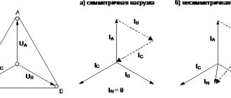
Connecting the generator windings to a three-phase network
Currents are taken from three separate windings of the generator and flow through different wires to the load. In electrical engineering, these conductors are called phases. The fourth core is the neutral wire, which is ultimately connected to the grounding bus in distribution boards, transformer substations and generators. Such circuits are called circuits with a grounded neutral. A phase in electricity is a conductive part along which charged particles move from the generator to the load. To understand what zero is, or why a neutral core is needed, you can compare electric current with the flow of water.