Mixed inclusion of capacitive storage devices in a circuit
The parallel and series connection of capacitors in one of the sections of the circuit circuit is called a mixed connection by specialists.
Section of the circuit of mixed-connected capacity storage devices:
The mixed connection of capacitors in the circuit is calculated in a certain order, which can be represented as follows:
- the circuit is divided into sections that are easy to calculate; this is a series and parallel connection of capacitors;
- we calculate the equivalent capacitance for a group of capacitors connected in series in a parallel connection section;
- we find the equivalent capacity in a parallel section;
- when the equivalent storage capacities are determined, it is recommended to redraw the diagram;
- The capacity of the resulting electrical energy storage devices after sequential switching on is calculated.
Capacitance storage devices (double-terminal networks) are connected in different ways to the circuit; this provides several advantages in solving electrical problems compared to traditional methods of connecting capacitors:
- Use for connecting electric motors and other equipment in workshops, in radio engineering devices.
- Simplifying the calculation of electrical circuit values. Installation is carried out in separate sections.
- The technical properties of all elements do not change when the current strength and magnetic field change; this is used to turn on different storage devices. It is characterized by a constant value of capacitance and voltage, and the charge is proportional to the potential.
Capacitor connection diagrams - capacitance calculation
To bookmarks
This article provides various diagrams for connecting capacitors, as well as formulas for calculating them with an example.
Series connection of capacitors
If we conditionally divide the terminals of each capacitor into the first and second terminals, the series connection of the capacitors will be performed as follows: the second terminal of the first capacitor is connected to the first terminal of the second capacitor, the second terminal of the second capacitor is connected to the first terminal of the third, and so on. Thus, we get a group (block) of series-connected capacitors with two free terminals - the first terminal of the first capacitor in the block and the second terminal of the last capacitor, through which this capacitor block is connected to the electrical circuit.
The series connection diagram of capacitors will look like this:
In fact, the series connection of capacitors is as follows:
With this connection scheme, the charges on the capacitors will be the same:
Qtot=Q1=Q2=Q3,
where: Q1, Q2, Q3 - respectively the charge on the first, second, third, etc. capacitors
The voltage on each capacitor with this circuit depends on its capacitance:
U1=Q/C1; U2=Q/C2; U3=Q/C3, where:
- U1, U2, U3 - respectively, the voltage on the first, second, third capacitors
- C1, C2, C3 - respectively, the capacitance of the first, second, third capacitors
In this case, the total voltage will be:
Utot=U1+U2+U3+…+Un
The total capacitance of capacitors in a series connection can be calculated using the following formulas:
- When connecting two capacitors in series:
Comm=(C1*C2)/(C1+C2)
- When three or more capacitors are connected in series:
1/Comm=1/C1+1/C2+1/C3+…+1/Cn
Parallel connection of capacitors
If we conditionally divide the terminals of each capacitor into the first and second terminals, the parallel connection of the capacitors will be performed as follows: the first terminals of all capacitors are connected to one common point (conditionally - point No. 1) the second terminals of all capacitors are connected to another common point (conventionally - point No. 2). The result is a group (block) of parallel-connected capacitors, the connection of which to the electrical circuit is made through conditional points No. 1 and No. 2.
The parallel connection diagram of capacitors will look like this:
Thus, the parallel connection of capacitors will look like this:
With this circuit, the voltage on all capacitors will be the same:
U=U1=U2=U3
The charge on each capacitor will depend on its capacity:
Q1=U*C1; Q2=U*C2; Q3=U*C3
In this case, the total charge of the circuit will be equal to the sum of the charges of all parallel connected capacitors:
Qtot=Q1+Q2+Q3…+…Qn.
The total capacitance of capacitors in a parallel connection can be calculated using the following formula:
Commun=C1+C2+C3+…+Cn
Mixed connection of capacitors
A circuit in which there are two or more groups (blocks) of capacitors with different connection patterns is called a mixed connection circuit of capacitors.
Here is an example of such a diagram:
For calculations, such circuits are conditionally divided into groups of identically connected capacitors, after which calculations are carried out for each group according to the formulas given above.
For clarity, we give an example of calculating the total capacity of this circuit.
Calculation example
Conditionally dividing the diagram into groups, we get the following:
As can be seen from the diagram, at the first stage we identified 3 groups (blocks) of capacitors, with the capacitors in the first and second groups connected in series, and the capacitors in the third group in parallel.
Let's calculate each group:
- Group 1 - series connection of three capacitors:
1/C1,2,3 = 1/C1+1/C2+1/C3 = 1/5+1/15+1/10=0.2+0.067+0.1 = 0.367 → C1,2,3 = 1/0.367 = 2.72 µF
- Group 2 - series connection of two capacitors:
C4.5 = (C4*C5)/(C4+C5)= (20*30)/(20+30) = 600/50 = 12 µF
- Group 3 - parallel connection of three capacitors:
C6,7,8 = C6+C7+C8 = 5+25+30 = 60 µF
As a result of the calculation, the scheme is simplified:
As you can see in the simplified diagram, there remains one more group of two parallel-connected capacitors; let’s calculate its capacitance:
- Group 4 - parallel connection of two groups of capacitors:
C1,2,3,4,5 = C1,2,3+C4,5 = 2.72+12 = 14.72 µF
Ultimately, we get a simple circuit of two series-connected groups of capacitors:
Now you can determine the total capacity of the circuit:
Total = (C1,2,3,4,5*C6,7,8)/(C1,2,3,4,5+C6,7,8) = 14.72*60/14.72+60 = 883.2/74.72 = 11.8 µF
Was this article useful to you? Or maybe you still have questions ? Write in the comments!
Didn’t find an article on the website on a topic that interests you regarding electrical engineering? Write to us here. We will definitely answer you.
↑ Up
5
https://elektroshkola.ru/elektrotexnicheskie-raschety/sxemy-soedineniya-kondensatorov-raschet-emkosti/
Serial connection
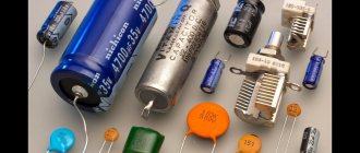
A capacitor, or in common parlance a “capacity”, is a part that no electrical or electronic board can do without. Even in modern gadgets it is present, albeit in a modified form.
Let us remember what this radio element is. This is a store of electrical charges and energy, 2 conductive plates, between which a dielectric is located. When a DC source is applied to the plates, current will briefly flow through the device and it will charge to the source voltage. Its capacity is used to solve technical problems.
The word itself originated long before the device was invented. The term appeared back when people believed that electricity was some kind of liquid that could be filled with some kind of vessel. In relation to the capacitor, it is unsuccessful, because implies that the device can only accommodate a finite amount of electricity. Although this is not true, the term has remained unchanged.
The larger the plates and the smaller the distance between them, the greater the capacitance of the capacitor. If its plates are connected to any conductor, then a rapid discharge will occur through this conductor.
In coordinated telephone exchanges, with the help of this feature, signals are exchanged between devices. The length of the pulses required for commands, such as: “line connection”, “subscriber answer”, “hang up”, is regulated by the capacitance of the capacitors installed in the circuit.
The unit of measurement for capacitance is 1 Farad. Because Since this is a large value, they use microfarads, picofarads and nanofarads (μF, pF, nF).
In practice, by making a series connection, you can increase the applied voltage. In this case, the applied voltage is received by the 2 outer plates of the assembled system, and the plates located inside are charged using charge distribution. Such methods are resorted to when the necessary elements are not at hand, but there are parts of other voltage ratings.
What is the difference between parallel and serial connection?
When conductors are connected in series, the current in all conductors is the same. In this case, the total voltage in the circuit is equal to the sum of the voltages at the ends of each of the conductors. In a parallel connection, the voltage drop between the two nodes connecting the elements of the circuit is the same for all elements.
Interesting materials:
Who is management and what does it do? Who is a claimant in enforcement proceedings? Who fills out the declaration of product conformity on whose initiative and when does the declaration become a document confirming compliance? Where does fat go when we lose weight? Where can I go if the power goes out? Where is Schengen 2022 needed? Where should I go to get a divorce? Where should I go to start paying alimony? Where should I go to file for divorce? Where should I go to get a divorce?
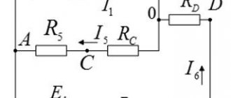
1.12. Electrical capacity
Electrical capacitance characterizes the ability of a body or system of bodies to accumulate electrical charges, thus storing the energy of the electric field.
Capacitance is defined as the ratio of the charge of an isolated conducting body to its potential (provided that the point at which the potential is taken equal to zero lies at infinity):
С = q/U,
and the capacitance of two conducting bodies separated by a dielectric and charged with charges of equal value and opposite in sign - as the ratio of the absolute value of the charge to the potential difference of these bodies:
С=q/(U1 – U2).
(1.15)
Capacitance depends on the geometric dimensions, configuration, dielectric constant of the dielectric and the relative position of the bodies.
Capacitance is measured in Farads (F).
Below are expressions for the capacities of the simplest systems.
The capacitance of a flat capacitor with a single-layer dielectric is equal to:
С = (eS)/d,
where S is the area of each plate; d – distance between plates.
The capacitance of a flat capacitor with a two-layer dielectric with dielectric constant e1 and e2 of each layer and their thickness equal to d1 and d2 is determined by the expression
.
(1.16)
Capacitance per unit length of a cylindrical capacitor (coaxial cable) with a single-layer dielectric and plate radii R1 and R2 (R12):
.
(1.17)
The capacitance of a spherical capacitor with the outer radius of the inner spherical plate R1 and the inner radius of the outer spherical plate R2 is determined by the expression
.
(1.18)
The capacity of a solitary sphere of radius R is:
C = 4peR.
(1.19)
Capacity of two spheres of radii R1 and R2 located at a distance D (geometric and electrical axes coincide)
.
(1.20)
Capacity of a solitary cylinder with radius R and length l:
.
If the length of the cylinder is much greater than its radius (l>>R), then the capacity can be determined using the approximate formula
. (1.21)
In the presence of several charged conductors, the concept of partial capacitances and equivalent system capacitance is introduced.
Partial capacitance is the capacitance between two conductors included in a conductor system. The partial capacitance between two conductors is defined as the absolute ratio of the charge on one conductor to the potential difference between those conductors when the other conductors in the system are at the same potential.
Equivalent capacitance (working) – the capacitance between two conductors included in a conductor system, taking into account the partial capacitance between a pair of wires of the system.