The KGTP cable is designed for supplying and distributing alternating or direct electricity to consumers. Designed to operate with alternating voltage not exceeding 660 volts, frequency up to 400 Hz and direct voltage not exceeding 1000 V.
Used to supply power to installations operating outdoors in adverse conditions.
Description and design of the KG cable
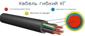
KG is a flexible power cable with copper conductors with insulation and a rubber sheath without protective covers (armor).
Explanation of the designation:
"K" - cable; "G" - flexible.
The most common KG cables are in the usual version with one, two or three main conductors and three main conductors and a grounding conductor (the so-called “three plus”).
To the designation of a KG cable in a tropical version, add the letter “T” through a hyphen (example: KG-T), for a cable in a cold-resistant version – add the letters “HL” through a hyphen (example: KG-HL).
The letter “n” is added to the designation of cables with a neutral conductor (example: KGn), the letter “v” is added to the designation of cables with one or two auxiliary conductors (without grounding and neutral conductors) (example: KGv).
Example of designation: KGn - KHL 2x25+ 1x16 - KG cable with a zero core in the “HL” version with two main cores with a cross-section of 25 mm2.
Since KG cables are intended for intensive operation in a wide temperature range, the technical specifications establish requirements for structural, electrical and mechanical parameters for both new cables and limit standards for cables during operation.
KG cables can have from one to five cores with a cross-section from 0.75 mm2 to 120 mm2.
The range of cross-sections of the main cores depending on the total number of cores is shown in the table.
| Number of cores | Nominal cross-section, mm 2 | ||
| Main | Neutral or ground | Auxiliary | |
| 1 | — | — | 2,5-120 |
| 2 and 3 | — | — | 0,75 – 120 |
| 2 and 3 | 1 | — | |
| 2 and 3 | — | — | 2,5 – 70 |
| 2 and 3 | — | 2 | 2,5 – 70 |
| 4 | — | — | 1,0 — 95 |
| 5 | — | — | 1,0 – 25 |
The cross-sections of neutral conductors, grounding and auxiliary conductors, depending on the cross-section of the main conductors up to 50 mm2, are given below. At the request of the consumer, other sections of the grounding conductor are allowed.
| Main veins | 0,75 | 1,0 | 1,5 | 2,5 | 4 | 6 | 10 | 16 | 25 | 35 | 50 |
| Zero core | 0,75 | 1,0 | 1,5 | 2,5 | 2,5 | 4 | 6 | 10 | 16 | 16 | 25 |
| Grounding conductor | 0,75 | 1,0 | 1,0 | 1,5 | 2,5 | 4 | 6 | 6 | 10 | 10 | 16 |
| Auxiliary core | — | — | 1,5 | 1,5 | 2,5 | 4 | 6 | 6 | 10 | 10 | 10 |
Current-carrying conductors must be twisted from individual copper wires (for tropical cables made of tinned) with a single wire diameter not exceeding that indicated in the table.
| Nominal conductor cross-section | 0,75 | 1,0 | 1,5 | 2,5 | 4 | 6 | 10 | 16 | 25 | 35 | 50 |
| Maximum single wire diameter | 0,21 | 0,21 | 0,26 | 0,26 | 0,31 | 0,31 | 0,41 | 0,41 | 0,416 | 0,41 | 0,41 |
The rubber insulation must be separated from the core without sticking, for which purpose a synthetic film can be laid between the core and the insulation.
The nominal and minimum values of the radial insulation thickness for cables with a cross-section of up to 50 mm2 are given in the table.
| Nominal cross-section, mm 2 | Nominal insulation thickness, mm | Minimum insulation thickness, mm |
| 0,75 – 1,5 | 0,8 | 0,62 |
| 2,5 | 0,9 | 0,71 |
| 4 and 6 | 1,0 | 0,8 |
| 10 and 16 | 1,2 | 0,98 |
| 25 and 35 | 1,4 | 1,16 |
| 50 | 1,6 | 1,34 |
The insulated conductors must have a distinctive color (the preferred one is shown in the table), while the insulation of the neutral conductors should be blue, and the insulation of the grounding conductors should be yellow-green (designation with the number “0” is allowed). The coloring must be continuous along the length; coloring in the form of a longitudinal stripe with a width of at least 2 mm is allowed.
| Number of cores | Preferred color scheme for core insulation | |
| With grounding conductor | With a neutral conductor and without a grounding conductor and a neutral conductor | |
| 3 | Yellow-green, blue, brown | Blue, black, brown |
| 4 | Yellow-green, blue, black brown | Blue, black, brown, black or brown |
| 5 | Yellow-green, blue, black brown, black or brown | Blue, black, brown, black or brown, black or brown |
Insulated conductors must be twisted, and twisting with an alternating change in direction is allowed for cables with a cross-section of the main conductors of 10 - 95 mm2.
It is allowed to twist cores with intercore filling in the form of bundles of rubber or synthetic threads.
The sheath must be applied in such a way that it can be easily separated from the core insulation. To do this, a synthetic film can be laid between the core insulation and the sheath. The shell color is predominantly black. In single-core cables, it is allowed to replace the insulation and sheath with an insulating protective sheath, applied in one layer with a thickness of at least twice the thickness of the insulation. The nominal and minimum values of the sheath thickness of the most common cable sections up to 50 mm2 are given in the table.
| Cable cross-section, mm2 | Nominal shell thickness, mm | Minimum shell thickness, mm |
| 1x10 | 1,8 | 1,43 |
| 1x16 | 1,9 | 1,52 |
| 1x25 | 2,0 | 1,6 |
| 1x35 | 2,2 | 1,77 |
| 2x1.5 | 1,5 | 1,18 |
| 2x2.5 | 1,7 | 1,35 |
| 2x4 | 1,8 | 1,43 |
| 3x1.5 | 1,6 | 1,26 |
| 3x2.5 | 1,8 | 1,43 |
| 3x4 | 1,9 | 1,52 |
| 3x1.5+1x1.5 (4x1.5) | 1,7 | 1,35 |
| 3x2.5+1x1.5 | 1,9 | 1,52 |
| 3x4+1x2.5 | 2,0 | 1,6 |
| 3x6+1x4 | 2,1 | 1,69 |
| 3x10+1x6 | 3,3 | 2,71 |
| 3x16+1x6 | 3,5 | 2,88 |
| 3x25+1x10 | 3,8 | 3,13 |
| 3x35+1x10 | 4,4 | 3,64 |
| 3x50+1x16 | 4,8 | 3,98 |
The difference between the maximum and minimum values of the outer diameter of the cable measured in one section (ovality) should not exceed 15% of the outer diameter.
Decoding
The product is marked in an alphanumeric code, which is easy to decipher.
For example, CGTP 2x2.5*0.66 means:
- "K" - cable;
- "G" - flexible;
- “T” - core shell made of thermoplastic elastomer;
- “P” - outer braid made of stabilized thermoplastic elastomer, resistant to sunlight;
- “2x2.5” - 2 cores with a cross-section of 2.5 mm2 each.
- “0.66” - what alternating voltage in the network the wire is designed for, indicated in kV, here 660 V.
The last number may not be there - it all depends on the manufacturer.
Wire modifications differ and therefore have additional symbols in their designations. Information is easy to find in directories and certificates for products sold. For example, in the designation “KGTP-KhL-1x2.5” the same KSTP is encrypted, but in a cold-resistant design with one 2.5 mm2 conductor.
For cables and wires for non-stationary installation, after the first letter (k) in the marking there is a letter indicating the flexibility class. In addition to “g” - flexible, there may be the letters “pg” or “og” - increased or special flexibility, respectively.
Products differ in design and thickness of the wire from which the core is “assembled”.
Conditions for installation and operation of the KG cable
The cable in the standard version is intended for operation at ambient temperatures from minus 40°С to plus 50°С, in the tropical version – from minus 10°С to plus 55°С, in the cold-resistant version – from minus 60°С to plus 50° WITH. Can be laid without preheating at a temperature not lower than minus 40°C. The bending radius during installation and operation must be at least 8 outer diameters of the cable, tensile forces must not be more than 2 kgf per 1 mm2 of the total copper cross-section of all cores. Service life is 4 years from the date of manufacture of the cable.
Main areas of operation
The most common CGs encountered during work are:
- on rivers and lakes;
- in the seas (if protected from salt);
- on the land;
- on open air;
- in enclosed spaces, large workshops;
- on naval vessels;
- in areas with temperate, cold and tropical climates.
KG is not used for laying underground. This is due to the fact that the insulation cannot withstand large mechanical loads, which provokes damage to the cable itself under soil pressure.
Technical characteristics of the KG cable
The electrical resistance of copper conductors at direct current for cables with a cross-section of up to 50 mm2 when supplied from the manufacturer must be no more than that indicated in the table.
| Nominal conductor cross-section | 0,75 | 1,0 | 1,5 | 2,5 | 4 | 6 | 10 | 16 | 25 | 35 | 50 |
| Core resistance, Ohm/km | 26,0 | 19,5 | 13,3 | 7,98 | 4,95 | 3,3 | 1,91 | 1,21 | 0,78 | 0,554 | 0,386 |
During storage and operation, the electrical resistance of the current-carrying cores of the KG cable should not increase by more than 10% of that indicated in the table.
The electrical resistance of cable insulation when delivered from the manufacturer, recalculated per 1 km of length at a temperature of 20°C, must be at least 50 MOhm, and during the entire period of storage and operation it must not decrease less than 1 MOhm. Finished cables must withstand testing with an alternating voltage of 2.5 kV at a frequency of 50 Hz for 5 minutes.
Cables must withstand multiple bends (with a cross-section of main cores up to 4 mm2 - at least 30,000 bends, with a cross-section of 6-16 mm2 - at least 9,000, with a cross-section of 25-50 mm2 - at least 6,000).
Popular manufacturers
Domestic and Belarusian manufacturers are leading the Russian cable market:
- JSC "Schuchinsky", Republic of Belarus, produces products in accordance with TU RB 05755944-005-93. The core cross-section is up to 95 mm2, other characteristics and requirements correspond to Russian ones.
- Cable, Pskov region, Velikiye Luki. Product regulations GOST 24334-80, TU 3544-007-41580618-2013. Operating voltage 0.38 and 0.66 kV. The maximum cross-section of cores is up to 240 mm2.
- OJSC "Arzamas Cable Plant" complies with the requirements of GOST 24334-80, TU 3540-004240073-001-2012. The core cross-section ranges from 0.75 to 95 mm2.
- JSC "Marposadkabel", Chuvash Republic, city of Mariinsky Posad. Specializes in the production of modifications of KG cables for shipbuilding, mines, etc. KSTP issues directly under separate contracts.
- “Rybinskkabel”, Russia, Rybinsk city.
- "Kaluga Cable Plant", Kaluga region, Zhiletovo village.
It is impossible to give the exact price of each manufacturer's products, since it is necessary to take into account the volume of the order and the cost of delivery to the buyer's region. All factories have certificates of conformity for their products and are responsible for quality control.
CGTP are products of the latest generation, safe for the user and durable. The products are excellent for use in adverse conditions and can be used at home, in small and large enterprises.
Requirements for packaging of KG cable
Cables can be supplied on drums or in coils. The diameter of the drum neck or the internal diameter of the coil must be no less than 12 external diameters of the cable.
Standard cable lengths must be at least 150 m for sections up to 35 mm2 inclusive and at least 125 m for sections from 50 mm2 and above. In one delivery batch, a certain percentage (no more than 20) of cables with a length of at least 20 m is allowed. No more than 5 pieces of cable can be wound on a drum. Cable lengths when supplied in coils are agreed upon between the manufacturer and the consumer.
Design
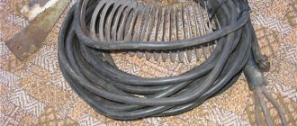
This brand of cable is distinguished by the fact that it has rubber insulation. Unlike polyvinyl chloride, rubber is extremely flexible and soft. There are no restrictions on the number of compressions and stretches. It works almost until the moment of self-destruction, which occurs as a result of the natural aging process. And this process can last more than ten years, depending on operating conditions.
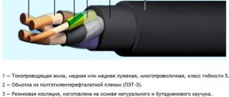
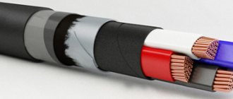
The conductor is twisted from thin (sometimes tinned) copper wires. Stranded conductors are covered with rubber insulation. (see Fig. 2)
Figure 2. KG cable structure
The letters indicate:
- A – outer shell;
- B – stranded core:
- C – core insulation.
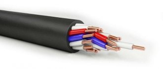
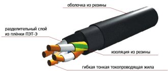
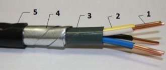
There may be options in the design of products: depending on the design features, the core insulation may be made of silicone rubber or it may not be present at all in large cross-section single-core cables. A single copper core, or their entire package, can be placed in a thin PET-E synthetic film, used as additional protection for the wires. This entire structure is covered with a rubber shell. Figures 3 and 4 show samples of single-core wires of different designs.
Figure 3. Flexible single-core cable KG with a large cross-section Figure 4. Cable KG, which uses film for winding the core
Core markings are color or digital. Light blue identification is used only for grounded line conductor. Yellow-green longitudinal stripes indicate grounding conductors. However, it is not allowed to use these colors to mark the cores separately. Other colors are used in accordance with international standards.
The number of conductive cores ranges from 1 to 5 pieces, with a cross-section from 1 mm2 to 240 mm2. To insulate them, RTI-1 or RTI-2-HL rubber is used. The outer sheath is made of rubber type RShT-2, RShTM-2 or RTISH (used in single-core cables).
Requirements for marking cable KG
Cables must be marked in the form of an inscription printed on the surface of the sheath or in the form of a tape under the cable sheath along the entire length or in the form of a distinctive thread. The inscription made on the surface of the sheath or tape must contain the trademark or name of the manufacturer and the year of manufacture of the cable. Cables in cold-resistant design must be additionally marked with the letters “ХЛ”. Marking in the form of an inscription can be made in relief or printed. The distance between inscriptions should not exceed 550 mm on the shell and 275 mm on the tape.
The drum cheek or label attached to the coil or drum must indicate:
— trademark or name of the manufacturer; — symbol of the cable (full indicating the number of cores and cross-section); — length of each cable section in meters; — gross weight in kilograms (determined approximately by calculation, based on the actual length and estimated weight); — date of manufacture (year, month); — drum or coil number. The label must bear a technical control stamp and a certification mark.
CGTP cable arrangement
Available in single-core and multi-core. Each core consists of thin copper conductors assembled together, having an insulating coating of styrene thermoplastic.
For ease of connection, each conductor has its own color. The color is standardized. The insulation of the neutral wire is blue or cyan, and the ground wire is yellow-green.
In two, three and four-core cables, the conductors are twisted together. The twist pitch should not exceed 16 diameters along the entire length. And in a five-core one, the conductors wrap around the cord. It is made from hose rubber or made from synthetic fabrics.
Copper, which has increased flexibility, is used as a conductive material. To better separate the outer insulation from the conductors, talc is used as a separator.
Multicore cables are produced with the same cross-section. If the product contains a grounding electrical wire, in addition to the color difference, it has a smaller diameter. In the manufacture of single-core conductors, the outer insulation is made of thermoplastic elastomer.
Weight and size parameters of cable KG
The approximate external dimensions and weights of individual cables with a cross-section of up to 50 mm2 for packaging and transportation purposes are given in the table. The given values may differ for cables of different batches and manufacturers by 10% less or more.
| Cable cross-section | External size value for packaging and transportation purposes, mm | Weight value for packaging and transportation purposes, kg/km |
| 1x10 | 11,1 | 230 |
| 1x16 | 12,4 | 310 |
| 1x25 | 14,6 | 450 |
| 1x35 | 16,4 | 590 |
| 2x1.5 | 9,4 | 130 |
| 2x2.5 | 11,2 | 190 |
| 2x4 | 13,5 | 280 |
| 3x1.5 | 10,1 | 160 |
| 3x2.5 | 12,0 | 230 |
| 3x4 | 14,5 | 350 |
| 3x1.5+1x1.5 (4x1.5) | 11,1 | 200 |
| 3x2.5+1x1.5 | 13,2 | 280 |
| 3x4+1x2.5 | 15,5 | 400 |
| 3x6+1x4 | 18,0 | 560 |
| 3x10+1x6 | 23,4 | 950 |
| 3x16+1x6 | 27,6 | 1300 |
| 3x25+1x10 | 33,1 | 1950 |
| 3x35+1x10 | 36,5 | 2400 |
| 3x50+1x16 | 42,4 | 3400 |
Choosing a cable for welding
The stability of welding work is influenced not only by the characteristics of the voltage source, but also by the parameters of the network and welding cable. Therefore, the correct selection of length, section and material from which it is made is of great importance. Welding currents in some cases reach 300 A or more, and we will tell you how to choose the right type and material for your job. We will also consider the topic of welding optical fiber cables, the composition of the equipment necessary for this and the sequence of work.
Parameters, types and selection of welding cable
Any welding cable has a certain electrical resistance, which can be calculated using tables, for example, an aluminum conductor has a higher resistance than a copper one. Therefore, a network extension cord will require a larger cross-section and a significant number of kilograms of aluminum wire. Taking this factor into account, the network wires are extended by no more than 40 m and a two- or three-core copper cable with a cross-section of more than 2.5 mm2 is chosen for this. Unlike network wires, welding cables are selected based on the output current and use stranded copper grades with improved insulation and increased flexibility.
The most common cables for welding are marked KG (flexible) or KOG (increased flexibility) and have multi-layer insulation of current-carrying conductors with a rubber outer coating. The wire length is usually 2-3 m because increasing this parameter by 1 m requires an increase in cross-section by 1.5 times the calculated one due to increased resistance and excessive heating. When choosing a product brand, it is necessary to take into account the operating conditions in order to select the type of insulation resistance to mechanical damage and temperature conditions. The conductor is marked depending on operating conditions as follows:
- welding cable type KG T 1X16 means tropical (T) version from -10 to +55 °C, single-core with a core cross-section of 16 mm2;
- product KOG HL 1X50 means cold-resistant (HL) from -60 to +50 °C, with an effective cross-section of 50 mm2;
- if the heat resistance index is not present, then the conductor can withstand from -40 to +50 °C;
Of particular importance is the cross-section of the welding cable, on which the strength of the operating current and the efficiency of the process depend. The choice for this parameter is based on matching the expected current strength and the cross-section of the conductive core according to the following principle:
- current up to 180 A is allowed to work with the KG 1X16 brand;
- at a current of 230 A, KG 1X25 is suitable;
- current 280 A allows work with a core cross-section of 35 mm2;
- 350 A corresponds to type KG 1X50;
- brand KG 1X70 allows a current of 430 A;
Welding of fiber optic lines
Modern technology allows us to avoid signal loss when transmitting over long distances; fiber optics are used for this. The product contains translucent threads with a reflective coating, through which the high-frequency signal passes without attenuation. The optical cable is laid for communication needs for various purposes and is an noise-proof, encrypted transmission link between subscribers. There are multimode and single-mode lines that differ in signal quality and price, but provide ideal isolation between communication nodes.
When installing lines of this kind, it becomes necessary to weld the fiber optic cable, which is a complex engineering task, since the thickness of the central core is 62.3 microns. For this purpose, special welding devices are used, which minimize quality losses and consist of the following components, namely:
- video control unit with monitor;
- heat shrink device with carriage and electric drive;
- guides with optical and mechanical correction systems;
- fiber optic welding module with arc creation unit;
- processor control board with controllers;
- source of supply voltage and welding current.
Units for welding optical waveguides have autonomous, classified software and an interface that allows maintaining high confidentiality of data transmission.
Let's sum it up
We examined the topic of choosing a welding cable, its varieties and operating conditions. It is very important to make the right decision to avoid extreme equipment operation and accidents. We also touched upon the topic of welding fiber optic lines and equipment for this work. We will be glad if this information is useful to you.
Sergey Odintsov
electrod.biz
KG cable load currents
The maximum permissible load currents at an ambient temperature of 25°C for cables with a cross-section of up to 50 mm2 are indicated in the table.
| Nominal cross-section, mm2 | Permissible load current, A | ||
| With one main residential | With two main cores | With three main cores | |
| 0,75 | — | 24 | 22 |
| 1,0 | — | 28 | 24 |
| 1,5 | — | 35 | 31 |
| 2,5 | 59 | 47 | 42 |
| 4 | 89 | 60 | 55 |
| 6 | 115 | 75 | 69 |
| 10 | 144 | 97 | 88 |
| 16 | 189 | 128 | 116 |
| 25 | 240 | 162 | 150 |
| 35 | 298 | 200 | 180 |
| 50 | 362 | 245 | 226 |
–
| , | , | -, |
| – 1×16-0.66 | 94.88 | |
| – 1×35-0.66 | ||
| – 1×70-0.66 | 595.65 | |
| – 1×25-0.66 | 195.75 | |
| – 1×50-0.66 | 356.26 | |
| – 1×70-1 | ||
| – 1×95-1 | ||
| – 1×10-0.66 | 82.39 | |
| – 1×120-1 | ||
| – 1×185-1 | ||
| – 1×150-1 | ||
| – 1×240-1 | ||
| – 1×95-0.66 | 787.26 | |
| – 1×1-0.66 | 11.61 | |
| – 1×1.5-0.66 | 14.52 | |
| – 1×0.75-0.66 | 9.82 | |
| – 1×6-0.66 | 49.57 | |
| – 1×2.5-0.66 | 21.84 | |
| – 1×4-0.66 | 34.13 | |
| – 1×120-0.66 | 998.6 | |
| – 1×150-0.66 | 1233.41 | |
| – 1×0.5-0.66 | 8.2 | |
| – 1×185-0.66 | 1503.62 | |
| – 1×240-0.66 | 1915.76 | |
| – 1×300-0.66 | ||
| – 1×400-0.66 | 2613.31 | |
| – 2×1.5-0.66 | 32.07 | |
| – 2×2.5-0.66 | 41.84 | |
| – 2×4-0.66 | 84.78 | |
| – 2×6-0.66 | 95.03 | |
| – 2×0.75-0.66 | 16.61 | |
| – 2×1-0.66 | 26.73 | |
| – 2×10-0.66 | 192.17 | |
| – 2×16-0.66 | 288.44 | |
| – 2×25-0.66 | 449.66 | |
| – 2×35-0.66 | 605.88 | |
| – 2×0.5-0.66 | 17.17 | |
| – 2×16+1×6-0.66 | 303.32 | |
| – 2×10+1×6-0.66 | 224.26 | |
| – 2×16+1×10-0.66 | 338.21 | |
| – 2×25+1×10-0.66 | 491.37 | |
| – 2×25+1×16-0.66 | 529.2 | |
| – 2×35+1×10-0.66 | 643.75 | |
| – 2×35+1×16-0.66 | 677.61 | |
| – 2×50+1×25-0.66 | 839.96 | |
| – 2×50+1×16-0.66 | 788.41 | |
| – 2×50-0.66 | 822.9 | |
| – 2×50+1×10-0.66 | 756.29 | |
| – 2×2.5+1×1.5-0.66 | 60.65 | |
| – 2×1.5+1×1.5-0.66 | ||
| – 2×4+1×2.5-0.66 | 98.29 | |
| – 2×6+1×4-0.66 | 135.43 | |
| – 2×185-0.66 | 2933.41 | |
| – 2×70-0.66 | 1202.32 | |
| – 2×240-0.66 | 3728.3 | |
| – 2×120-0.66 | 1976.64 | |
| – 2×150-0.66 | 2455.62 | |
| – 2×95-0.66 | 1592.68 | |
| – 3×4+1×1.5-0.66 | 137.92 | |
| – 3×6+1×4-0.66 | 164.1 | |
| – 3×6-0.66 | 152.88 | |
| – 3×10+1×6-0.66 | 345.57 | |
| – 3×16+1×6-0.66 | 378.55 | |
| – 3×1.5-0.66 | 40.51 | |
| – 3×2.5+1×1.5-0.66 | 71.27 | |
| – 3×2.5-0.66 | 61.83 | |
| – 3×4-0.66 | 106.77 | |
| – 3×4+1×2.5-0.66 | 130.24 | |
| – 3×1.5+1×1.5-0.66 | 64.89 | |
| – 3×25+1×10-0.66 | 798.18 | |
| – 3×35+1×10-0.66 | 1026.2 | |
| – 3×50+1×16-0.66 | 1443.62 | |
| – 3×70+1×25-1 | ||
| – 3×95+1×35-1 | ||
| – 3×0.75-0.66 | 22 | |
| – 3×1-0.66 | 28.22 | |
| – 3×16-0.66 | 415.44 | |
| – 3×10-0.66 | 289.98 | |
| – 3×120+1×35-1 | ||
| – 3×150+1×36-1 | ||
| – 3×70+1×25-0.66 | 2047.23 | |
| – 3×95+1×35-0.66 | 2705.31 | |
| – 3×120+1×35-0.66 | 3435.98 | |
| – 3×150+1×50-0.66 | 4350.04 | |
| – 3×1+1×1-0.66 | ||
| – 3×0.75+1×0.75-0.66 | ||
| – 3×35-0.66 | 912.73 | |
| – 3×25+1×16-0.66 | 741.42 | |
| – 3×25-0.66 | 673 | |
| – 3×35+1×25-0.66 | 1114.96 | |
| – 3×35+1×16-0.66 | 991.43 | |
| – 3×16+1×10-0.66 | 489.61 | |
| – 3×150-1 | ||
| – 3×120-1 | ||
| – 3×95-1 | ||
| – 3×50-0.66 | 1278.72 | |
| – 3×70-1 | ||
| – 3×0.5-0.66 | 21.59 | |
| – 3×50+1×10-0.66 | 1181.06 | |
| – 3×50+1×25-0.66 | 1343.65 | |
| – 3×120+1×50-0.66 | 3673.02 | |
| – 3×70+1×50-0.66 | ||
| – 3×95+1×70-0.66 | ||
| – 3×120+1×70-0.66 | 3336.26 | |
| – 3×150+1×70-0.66 | 4132.54 | |
| – 3×150+1×95-0.66 | ||
| – 3×185+1×70-0.66 | ||
| – 3×185+1×95-0.66 | 5380.32 | |
| – 3×185+1×120-0.66 | ||
| – 3×240+1×120-0.66 | ||
| – 3×50+1×35-0.66 | ||
| – 3×1.5+1×1-0.66 | 62.88 | |
| – 3×120-0.66 | 3171.25 | |
| – 3×10+1×4-0.66 | 330.11 | |
| – 3×150-0.66 | 3973.68 | |
| – 3×240-0.66 | 5707.81 | |
| – 3×6+1×2.5-0.66 | 200.15 | |
| – 3×185-0.66 | 3024.12 | |
| – 3×70-0.66 | 1898.74 | |
| – 3×95+1×50-0.66 | 2648.15 | |
| – 3×70+1×35-0.66 | 1931.28 | |
| – 3×95-0.66 | 2530.87 | |
| – 3×120+1×95-0.66 | 3527.13 | |
| – 4×1.5-0.66 | 47.65 | |
| – 4×2.5-0.66 | 79.3 | |
| – 4×4-0.66 | 117.73 | |
| – 4×6-0.66 | 172.9 | |
| – 4×10-0.66 | 347.93 | |
| – 4×16-0.66 | 425.8 | |
| – 4×25-0.66 | 889.9 | |
| – 4×35-0.66 | 1219.67 | |
| – 4×50-0.66 | 1416.44 | |
| – 4×70-1 | ||
| – 4×95-1 | ||
| – 4×120-1 | ||
| – 4×150-1 | ||
| – 4×120-0.66 | 4027.63 | |
| – 4×70-0.66 | 2416.57 | |
| – 4×95-0.66 | 3188.34 | |
| – 4×0.75-0.66 | 33.41 | |
| – 4×1-0.66 | 45.08 | |
| – 4×150-0.66 | 5006.18 | |
| – 4×185-1 | ||
| – 4×0.5-0.66 | 27.18 | |
| – 4×185-0.66 | 5788.34 | |
| – 4×240-0.66 | ||
| – 5×1.5-0.66 | 63.65 | |
| – 5×2.5-0.66 | 97.75 | |
| – 5×4-0.66 | 149.03 | |
| – 5×6-0.66 | 228.36 | |
| – 5×10-0.66 | 413.67 | |
| – 5×16-0.66 | 555.16 | |
| – 5×35-0.66 | 1520.77 | |
| – 5×25-0.66 | 862.17 | |
| – 5×50-0.66 | 1875.26 | |
| – 5×70-1 | ||
| – 5×95-1 | ||
| – 5×120-1 | ||
| – 5×150-1 | ||
| – 5×70-0.66 | 3023.55 | |
| – 5×95-0.66 | 3980.85 | |
| – 5×0.75-0.66 | 43.85 | |
| – 5×1-0.66 | 55.72 | |
| – 5×120-0.66 | 4660.27 | |
| – 5×0.5-0.66 | 32.97 | |
| – 5×185-1 | ||
| – 5×240-1 | ||
| – 5×150-0.66 | 6030.25 | |
| – 5×185-0.66 | 7063.07 | |
| – 5×240-0.66 | 9035.62 | |
| – 7×1-0.66 | ||
| – 7×2.5-0.66 | ||
| – 7×1.5-0.66 | ||
| – 7×0.5-0.66 | ||
| – 7×4-0.66 | ||
| – 7×0.75-0.66 | ||
| – 7×10-0.66 | ||
| – 7×6-0.66 | ||
| – 7×16-0.66 |
(179)
Available methods for quality control of KG cable
Control methods are presented that, although not strictly corresponding to the specifications, allow making preliminary conclusions about the quality of the cable if the measured values differ significantly from the regulated ones. The final conclusion about the compliance of the cable with the specifications can be made only after testing the cable in a specialized laboratory using strict methods and in the volumes specified in the technical specifications.
Visual inspection The following can be checked: the number and color of cores, the integrity of the insulation and sheathing and the ability to separate them without damage.
Measurement of structural dimensions Can be checked using suitable measuring instruments: thickness of insulation and sheath, diameter of wires in the core dpr. Calculating the cross-section of the core using the formula 0.785dpr2N (where N is the number of wires in the core) is not a strict method for controlling the cross-section of the cores, because confirmation of cross-section compliance is electrical resistance, however, a significant deviation of the calculated cross-section from the nominal (more than 15%) may serve as a basis for doubts about the quality.
Measurement of the electrical resistance of current-carrying conductors Can be carried out on a finished cable with an ohmmeter with a suitable measurement limit (for cables with a small cross-section at a normal length in a coil or on a drum, it can be several Ohms) and recalculated for a length of 1 km. If the cable has twisted cores, the obtained values should be reduced by 1.02 times. Particular attention should be paid to making good contact with the test leads.
Specialized brands
In addition to the usual KG or KG-chl, their modification KGE is also produced for industry.
Inside the sheath of such a cable there is a screen made of conductive rubber. If the cable cores are damaged, leakage immediately begins on this screen, followed by protection activation.
By the way, many consumers still for some reason confuse KG with other “mine” brands, for example GRSHE. I remember how miners in Soviet times carried such cables en masse to their homes and “freely” connected their residential buildings with them.
After a couple of years of stationary street operation of the cable, real problems began.
The electricians servicing these 0.4 kV overhead lines then cursed for a long time, trying to find a short circuit on a branched line with dozens of consumers. It seems that there is no overlap of wires, but the machine at the KTP knocks out.
So, in order to find the damage, it was necessary to throw away these “miners” first.
Special shielded grades of KG cable are still used in mines. However, there is no point in using them in everyday life.
Sections and dimensions of CGTP
By choosing the required cable size KGtp, you can clarify the values and descriptions of the following characteristics:
- weight and diameter
- current load
- short circuit current
- power
- resistance
- precise design
- marking
- KGtp 1x2.5
- KGtp 1x4
- KGtp 1x6
- KGtp 1x10
- KGtp 1x16
- KGtp 1x25
- KGtp 1x35
- KGtp 1x50
- KGtp 1x70
- KGtp 1x95
- KGtp 1x120
- KGtp 1x150
- KGtp 1x185
- KGtp 1x240
- KGtp 1x300
- KGtp 1x400
- KGtp 2x0.75
- KGtp 2x1
- KGtp 2x1.5
- KGtp 2x2.5
- KGtp 2x4
- KGtp 2x6
- KGtp 2x10
- KGtp 2x16
- KGtp 2x25
- KGtp 2x35
- KGtp 2x50
- KGtp 2x70
- KGtp 2x95
- KGtp 2x120
- KGtp 2x150
- KGtp 2x185
- KGtp 2x240
- KGtp 2x0.75+1x0.75
- КГтп 2х1+1х1
- KGtp 2x1.5+1x1.5
- KGtp 2x2.5+1x1.5
- KGtp 2x2.5+1x2.5
- KGtp 2x4+1x1.5
- KGtp 2x4+1x2.5
- KGtp 2x6+1x2.5
- KGtp 2x6+1x4
- KGtp 2x10+1x6
- KGtp 2x16+1x6
- KGtp 2x25+1x10
- KGtp 2x35+1x10
- KGtp 2x50+1x16
- KGtp 2x70+1x25
- KGtp 2x95+1x35
- KGtp 2x120+1x35
- KGtp 2x120+1x50
- KGtp 2x120+1x70
- KGtp 2x150+1x50
- KGtp 3x0.75
- KGtp 3x1
- KGtp 3x1.5
- KGtp 3x2.5
- KGtp 3x4
- KGtp 3x6
- KGtp 3x10
- KGtp 3x16
- KGtp 3x25
- KGtp 3x35
- KGtp 3x50
- KGtp 3x70
- KGtp 3x95
- KGtp 3x120
- KGtp 3x150
- KGtp 3x185
- KGtp 3x240
- KGtp 3x0.75+1x0.75
- КГтп 3х1+1х1
- KGtp 3x1.5+1x1
- KGtp 3x1.5+1x1.5
- KGtp 3x2.5+1x1.5
- KGtp 3x2.5+1x2.5
- KGtp 3x4+1x1.5
- KGtp 3x4+1x2.5
- KGtp 3x4+1x4
- KGtp 3x6+1x2.5
- KGtp 3x6+1x4
- KGtp 3x6+1x6
- KGtp 3x10+1x4
- KGtp 3x10+1x6
- KGtp 3x10+1x10
- KGtp 3x16+1x6
- KGtp 3x16+1x10
- KGtp 3x16+1x16
- KGtp 3x25+1x10
- KGtp 3x25+1x16
- KGtp 3x25+1x25
- KGtp 3x35+1x10
- KGtp 3x35+1x16
- KGtp 3x35+1x25
- KGtp 3x35+1x35
- KGtp 3x50+1x10
- KGtp 3x50+1x16
- KGtp 3x50+1x16+1x10
- KGtp 3x50+1x25
- KGtp 3x50+1x35
- KGtp 3x50+1x50
- KGtp 3x70+1x10
- KGtp 3x70+1x16
- KGtp 3x70+1x25
- KGtp 3x70+1x35
- KGtp 3x70+1x50
- KGtp 3x95+1x10
- KGtp 3x95+1x25
- KGtp 3x95+1x35
- KGtp 3x95+1x50
- KGtp 3x95+1x70
- KGtp 3x120+1x16
- KGtp 3x120+1x25
- KGtp 3x120+1x35
- KGtp 3x120+1x50
- KGtp 3x120+1x70
- KGtp 3x120+1x95
- KGtp 3x150+1x16
- KGtp 3x150+1x25
- KGtp 3x150+1x35
- KGtp 3x150+1x50
- KGtp 3x150+1x70
- KGtp 3x150+1x95
- KGtp 3x150+1x120
- KGtp 3x185+1x16
- KGtp 3x185+1x25
- KGtp 3x185+1x50
- KGtp 3x185+1x70
- KGtp 3x185+1x95
- KGtp 3x240+1x120
- KGtp 3x6+3x2.5
- KGtp 4x0.75
- KGtp 4x1
- KGtp 4x1.5
- KGtp 4x2.5
- KGtp 4x4
- KGtp 4x6
- KGtp 4x10
- KGtp 4x16
- KGtp 4x25
- KGtp 4x35
- KGtp 4x50
- KGtp 4x70
- KGtp 4x95
- KGtp 4x120
- KGtp 4x150
- KGtp 4x185
- KGtp 4x240
- KGtp 4x4+1x1.5
- KGtp 4x10+1x6
- KGtp 5x0.75
- KGtp 5x1
- KGtp 5x1.5
- KGtp 5x2.5
- KGtp 5x4
- KGtp 5x6
- KGtp 5x10
- KGtp 5x16
- KGtp 5x25
- KGtp 5x35
- KGtp 5x50
- KGtp 5x70
- KGtp 5x95
- KGtp 5x120
- KGtp 5x150
- KGtp 5x185
- KGtp 5x240