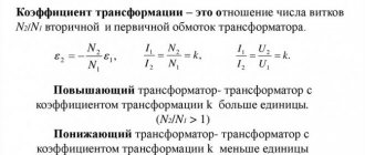
When organizing power supply to enterprises, residential and commercial facilities, in cases where the total load current many times exceeds the capabilities of the metering unit, or it is necessary to meter the electricity of high-voltage consumers, additional conversion units are installed - current transformers (CT) and voltage transformers (VT). They allow you to perform a linear conversion and meter or control the passing current using conventional single-phase or three-phase electric meters, ammeters, and also organize a line protection system using them. In this article we will learn how to choose a current transformer for an electricity meter based on power and other parameters.
Description and principle of operation
Current transformer is an electromagnetic converting device, structurally consisting of:
- one-piece magnetic circuit;
- two windings, necessarily isolated from each other and from the ground (primary and secondary);
- plastic sealed non-separable case;
- contact terminals for connecting a measuring device;
- fastening elements for mounting the device;
- plate on the case, paper passport.
The windings of the converter are divided among themselves into primary and secondary, and are included in the energy circuit strictly according to certain rules.
The primary winding is connected to the electrical circuit in series (cutting the conductor). The secondary winding is closed to a certain load of measuring elements, relay equipment and automation. It passes through itself an amount of current that is proportional to the current value of the primary winding.
The operating principle of any of them is based on the law of electromagnetic induction, which operates equally in the electric and magnetic fields of electrical machines and mechanisms.
Its essence is the conversion of the amount of current flowing through the power circuit of the power plant, to which the primary winding of a current transformer with a certain number of turns is connected, into a secondary reduced current value, while maintaining the proportionality of the value.
This proportional amount of electric current at the output terminals of the secondary winding of the transformer is necessary for the normal operation of measuring, relay equipment, and electricity metering devices in power energy systems up to and above 1000 volts.
There is a direct dependence of the nominal operation of all measuring systems, monitoring and control devices on the correct choice of current transformers.
Reliability of voltage instrument transformers in a network with an isolated neutral
A simple measuring device is designed to derate the voltage that is supplied to meters and protective relays connected to a 6-10 kV network. The transformer operates properly only when the neutral is grounded.
In case of ferroresonance reactions (power line phase failure, contact with branches, dew drops running down wires, incorrect switching), there are risks of voltage transformer breakdowns. The failure rates are 17 and 25 Hz. Under these conditions, an overcurrent flows through the primary winding and it burns out.
If the "Star-Star" circuit is used, under conditions of increasing voltage the induction of the magnetic circuit increases. The device burns out. You can prevent this process by:
- reduction of working induction rates;
- connecting resistance-damping devices to the network;
- creating a three-phase device with a common five-rod magnetic system;
- operation of devices connected to the network when the delta is opened;
- grounding of the neutral through a current-limiting reactor.
Classification
Converters, in addition to the areas of operation described above, are usually classified according to their main characteristics, knowledge of which is necessary for their correct selection in various power electrical installations.
Series transformers are usually classified according to:
By type of installation
The class of current measuring devices is divided into several options for general or special purposes:
- Portable – special-purpose transformers used for control measurements or tests in mobile electrical laboratories;
- Overhead – special-purpose conversion devices used in high-voltage installations by placing the bushing insulators of the network power transformer circuits on top;
- Built-in – special type instrument transformers used inside various electrical devices and machines to convert values of the internal circuit of the equipment;
- Indoor installation – general-purpose electrical devices used on high-voltage electrical distribution systems, or low-voltage power circuits (400V);
- Outdoor installation – general-purpose conversion devices used in open high-voltage distribution networks (over 1000V).
Precise determination of the equipment in the circuit section to which serial converters will be connected becomes one of the important criteria for their selection.
By installation method
The type differences in the housings of series transformers of the electrical network divide them by installation class into:
- Feedthroughs - play the role of a feedthrough insulator through a certain obstacle in the electrical installation system. The leads of their primary windings are always located at the top, the other at the bottom;
- Support - structurally have all primary terminals located on one side. They are always installed on a flat supporting surface.
Correctly determining the type of installation of a measuring device for current conversion will prevent errors in the further design of a new energy system or repair of an already created installation.
By type of insulation
Groups of conversion measuring instruments have differences in the composition of the insulation material of their windings and housings, and are divided into several main ones:
- Solid - type of dry insulation in the form of porcelain, bakelite and similar materials;
- Viscous - insulation obtained by pouring with various compounds.
- Mixed - the use of paper-oil elements as an insulating material;
- Gas - the primary winding is isolated from the secondary winding by an air gap.
The insulating material of the equipment is selected depending on the type of electrical installation where it is used. It also depends on the rated voltage at the installation site of the devices, the climatic conditions where the switchgear will be operated and other factors.
By the number of transformation steps
Transformers are divided into two main types in this classification section:
- Single-stage - such devices have one primary and one secondary winding in the device, one unchangeable transformation ratio;
- Multistage - electromagnetic devices of a cascade type, the device of which contains either the ability to change the number of turns of the primary or secondary winding, or contains several secondary windings with a trim of their number of turns. This design allows you to have multiple transformation ratios in one device;
The first class of transformers is the most common in the use of general-purpose power plants. The second type is used in specialized areas of distribution networks as needed.
By the number of secondary windings
Accordingly, based on the number of transformation stages, devices are divided into:
- With one secondary winding;
- With two or more secondary windings.
The main type of transformers in this division classifies the first type as a general-purpose device, and the second as a special-purpose type.
By purpose
The main purpose of this electromagnetic device is to transform current from one value to another. There are two main directions for using transformers:
- For measurements – transfer of measuring parameters to instruments, the readings of which are taken by electrical installation personnel in order to analyze the operation of high-voltage power plants (>1000V). The primary winding of the current transformer is connected to a break in the energy circuit, and the required measuring device, such as an ammeter, wattmeter windings or electricity meters, is connected to its secondary winding. Their installation is carried out in power installations where direct connection of measuring equipment and electric meter windings directly is impossible, but their normal functioning is necessary.
- For protection – transfer of measurement information to protection devices, or any control modules of the energy system in which they are included. Ensures isolated operation of these devices in high-voltage installations or power circuits with a voltage of 400V. Isolation of relays and control devices from the primary circuit of the installation ensures safe accessibility to such modules by maintenance personnel for their repair and operation.
Often current transformers have mixed functionality.
By voltage class
An important criterion for choosing conversion devices. It includes two main classes:
- For high-voltage distribution installations - 6/10/35 kilovolts and above - the use of converters in such networks has an increased size and some design differences;
- For low-voltage switchgear - applications up to 1000V - the most common voltage class for such devices is 400V. In this class, the dimensions of transformers depend on the rated currents of the primary windings, and the design has significant diversity depending on the type of installation and the location of their installation site.
Incorrect selection of voltage class when choosing transformers will make their use impossible in a designed or operating energy system or section of it.
By conversion method
Due to the development of progress in electrical engineering, this parameter is now included in the main classification of conversion devices, consisting of types:
- Electromagnetic - conversion devices based on copper wire windings with a solid steel core, the most common cost-effective type of transformers, widely used in various distribution networks;
- Optical-electronic is a new type of current value conversion, based on the progressively innovative design of electromagnetic devices, their insulation, using the latest materials. Higher in price, but with more accurate output parameters.
Summarizing the above classification of electromagnetic equipment, the conclusion on their correct choice on the surface is only a complete study of all the listed parameters of current conversion devices, comparing them with the parameters of the power system where they will be operated, will not allow making unforgivable mistakes in their selection, further installation and quality use .
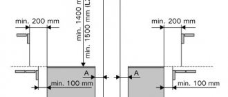
Device installation
IKK installation diagram
The devices are in demand when laying new electrical lines and when it is necessary to modernize them. During installation, the requirements of the PUE regarding the rules of operation of test boxes must be met. According to the regulations, to place the ICC it will be necessary to prepare a specially equipped place, protected from entry by unauthorized persons and accessible to service personnel.
It is allowed to connect only wires made of homogeneous metals that are electrochemically compatible at the terminals of the box.
The tightening force for contact screw connections should not exceed 2.5 Nm, which guarantees the safety of the terminals. In addition, they must not have any damage or traces of obvious defects. Fixing the IKK body at the installation site is carried out only mechanically - by screwing it or securing it using special latches. The box is usually mounted in the electrical cabinet immediately after the electric meter.
How to choose
The choice of current transformers (CTs) depends not only on knowledge of their classification in a general format, but also requires a correct assessment of many other transformer quantities. In electrical engineering, such values are usually called nominal parameters.
Ratings
The correct choice of CT consists of selecting your own nominal values, conducting test checks, the results of which will become fundamental for determining the required brand of transformers.
The main nominal parameters of the CT consist of:
Operating voltage
The value of the operating voltage - that is, the value of the effective voltage of the distribution installation where a certain instrument transformer is selected must be less than or equal to the rated voltage of the transformer. For effective selection, there is a standard range of operating voltage ratings, expressed in kilovolts: 0.66, 3, 6, 10, 15, 20, 24, 27, 35, 110, 150, 220, 330, 750.
CT primary current
The second main parameter for choosing a measuring device occurs in almost the same way as selecting the operating voltage: tabulated current standards of CT currents are compared with the value of the operating current of the circuit section or the entire electrical installation where the converter device is planned to be installed.
However, here one more criterion must be taken into account: in a network with active loads and general-purpose consumers, the ratings are selected without taking into account correction current margins, but for electrical equipment of generators, engines or other active-reactive consumers, it is necessary to take into account a 10% margin when choosing the primary CT current its size. This is due to surges in current values at the time of startup of such equipment.
The standard values by which the current of the primary winding of the transformer is selected are enclosed in a certain table row, the units of measurement are amperes: 1, 5, 10, 15, 20, 30, 40, 50, 75, 80, 100, 150, 200, 300, 400 , 500, 600, 750, 800, 1000, 1200, 1500, 1600, 2000, 3000, 4000, 5000, 6000, 8000, 10000, 12000, 14000, 16000, 18000, 20000, 25000, 28000, 30000, 32000, 35000 , 40000.
If the choice of primary current, taking into account the 10% margin, is between the standard values of the series, the larger of their values is taken.
However, here it is necessary to obtain data from two more mandatory tests of transformers in order to be completely sure of its correct choice:
Thermal resistance test
Thermal resistance ensures that the selected CT can withstand thermal shock and remain in normal operating condition, without any damage, in an emergency short circuit (SC) condition when a certain amount of short circuit current passes through it over a certain period of time. There is a special formula for test values for the thermal resistance of converter devices up to and above 1000 V.
If the selected transformer does not meet the calculated thermal resistance values, you should pay attention to another transformer model in order to avoid problems with the power plant during its further operation.
For electrodynamic resistance
This experimental-calculation process tests the selected transformer for resistance to the dynamic impact of short-circuit current on it during emergency operation in the circuit. An electromagnetic device must withstand such an impact for a certain period of time and remain in working condition.
Otherwise, a change in the brand or model of the transformer is required. The electrodynamic resistance test is determined by a special formula, which involves constant values and emergency mode values.
Secondary load power test
The third mandatory parameter for selecting a CT. The test is carried out by comparative analysis of the rated power of the CT and the total power of the secondary load over the entire section of the circuit in which the selected current transformer is planned to be installed. The power rating must be greater than or equal to the value in the existing or planned installation.
It is important to know that the total load power of the circuit is the sum of the resistances of all switching, measuring, relay devices and control equipment of the section multiplied by the square of the current of this equipment.
If the selection is carried out in the switchgear being designed, the resistance values are taken from the passport data of the equipment installed there; if the object is already operating, the resistance values are obtained by measuring the resistance of ohmmeters or other known methods.
Transformation ratio
This parameter is the final rating that must be taken into account for the correct selection of current transformers for instrumentation, relay system and control modules in distribution circuits.
The selection criterion for this parameter is divided into two options:
- From the minimum value of the transformation ratio - in this case, its value is taken based on the nominal value of the line of the switchgear into which the converter device is selected;
- From the maximum value of the transformation ratio - the value of the minimum transformation ratio multiplied by the ratio of the operating current of the line to the maximum value of the secondary winding current of the transformer.
The second parameter is regulated by the regulatory documents “PUE” (Rules for Electrical Installations) and is used when selecting current transformers used to power electricity metering windings.
Purpose
Taking into account the scope of application of transformers for their intended purpose establishes a strict choice of its accuracy class.
To power the commercial metering windings, it is necessary to select transformers with an accuracy class of at least 0.5. Household electricity metering limits the choice of transformation devices with accuracy class equal to 1
If the selection of CTs is made for measuring systems, such as ammeters, wattmeters, transformers with an accuracy class of at least 3 are selected
To power relay equipment or control devices in a distribution installation, the choice of transformers is dictated by a special high-rated accuracy class, which is designated 10 (P).
Without taking into account the scope of application, it is impossible to guarantee the correct choice of transformer, because its parameter called accuracy class significantly affects the accuracy of the readings taken and will be discussed in more detail in this article below.
Other criteria
Design institutes or technical specialists who select current transformers can be guided by other parameters for selecting converting devices for a section of a power plant circuit, such as:
- Determining the type of automation of the installation of the metering unit, which may affect the determination of the required accuracy class of the selected transformer;
- Calculations of the metering length and cross-section of conductors running from the transformer transformer to the metering devices in order to calculate the amount of voltage loss, which should have minimum percentage values;
- If a new power plant is designed from scratch, the method of converting the current value is taken into account.
- If the distribution network is operational, the current date of verification of the device becomes an important parameter for choosing a device. Transformation equipment should not have expired verification dates from metrological services.
Any current transformer parameter is selected based on and in accordance with the data described in the regulatory documentation of the “Rules and Devices of Electrical Installations”.
Appendix 7.1
| Term | Definition |
| Electric energy consumer | An organization, institution, geographically isolated workshop, object, site, building, apartment, etc., connected to electrical networks and using energy using existing electrical energy receivers |
| Subscriber | A consumer directly connected to the networks of an energy supplying organization, sharing with it a balance sheet boundary of electrical networks, whose right and conditions for using electrical energy are stipulated by an agreement between the energy supplying organization and the consumer or his superior organization. For household consumers - an apartment, building or group of territorially united buildings of personal property |
| Balance sheet limit | The point of division of the electrical network between the energy supplying organization and the subscriber, determined by the balance sheet of the electrical network |
| Electricity metering point | The point in the power supply diagram at which, using a measuring device (calculation meter, metering system, etc.) or another method, the values of electrical energy and power consumption used in commercial calculations are determined. The metering point corresponds to the balance sheet boundary of the electrical network |
| Calculation meter | Metering device, metering system based on the readings, which at the metering point determines the consumption of electrical energy by the subscriber (sub-subscriber) to be paid |
| Control metering device | A metering device, based on the readings of which at a given point in the network, the consumption of electrical energy used for control is determined |
| Connected consumer power | The total power of consumer transformers connected to the electrical network, which convert energy into operating (directly supplying pantographs) voltage and electric motors with voltages above 1000 V. In cases where power to consumer electrical installations is supplied from transformers or low-voltage networks of the energy supply organization, the connected power of the consumer is taken as permitted use of power, the size of which is established by the energy supply organization and is indicated in the contract for the supply of electrical energy |
Connection schemes
To power relay equipment, current windings for electricity metering for general or commercial purposes, there are three main circuits for connecting current transformers:
- "full star"
- "incomplete star";
- "triangle".
Each type of connection for various purposes optimizes the operation of measuring and metering systems of electrical equipment, and makes it possible to optimize the parameters of electricity metering in the circuits of new or existing distribution devices up to and above 1000 volts.
Electric meter characteristics
The performance indicators of the Mercury 230 device, which fully characterize it as a metering device, include the following capabilities:
- Display of data on consumed electricity for any of the provided operating modes: night, day, preferential, etc.
- Energy consumption accounting according to one of 4 tariff modes with 16 time overlap zones.
- Calculation and registration of current and frequency parameters.
- Consumption control via interface (from a central control center).
- Storing in the device’s memory up to 10 most important events, as well as moments of loss of individual phases, exceeding permissible values, dates of opening and changes in the tariff regime.
How to choose the right CT for relay protection
In order to correctly select current transformers for various relay protection and automation units, you should pay attention to several important parameters for their selection:
- The maximum and nominal voltage value in the primary winding of the transformer;
- Rated value of current in the primary winding;
- Accuracy class.
The last parameter has different values for different types of transformers, but for relay protection and automation units it has priority due to the fact that the accuracy of the output signal depends on it, in other words, the quality of power supply of the entire protection and automation unit. For more accurate operation of protection and automation systems in distribution networks, the use of transformers with an increased accuracy class of 10 (P) is used. A detailed discussion of the concept of accuracy class in the article is published below.
Using a Transition Test Box
- mounting a reference metering device into the metering unit;
- orientation of current in an electrical circuit through current loops;
- switching off current circuits;
- connection of phase conductors to the metering device.
The test adapter box (TCB) is designed to “short-circuit” (bypass) current circuits.
Selection of accuracy class
Current transformer parameter indicating that the measurement error of the current value of the secondary winding of the CT does not exceed the values specified in regulatory documents in accordance with GOST 7746-2011. According to this GOST, the nominal values of accuracy classes are as follows: 0.1, 0.2S, 0.2, 0.5, 0.5S, 1, 3, 5, 10.
For circuits of measuring instruments, metering equipment and relay protection systems, the accuracy classes of current converters will be different.
And for electricity metering of a general or commercial type, the usual accuracy classes of current converters are used equal to 1, 3. It should be added that to power measuring instruments such as ammeters and the like, current transformers with an accuracy class of 0.5 or increased accuracy are selected, the error of which is 0. 5S.
Automation and relay protection units require the use of high-precision equipment for their power sources in distribution networks, in which the error in the current value of the secondary winding of the transformer will not exceed 10% of the value. The marking of this accuracy class is 10 (P).
Rated secondary current
The structure of the secondary winding of current transformers, which are designed for voltages of no more than a thousand volts, has some differences. At least two secondary windings are installed on a high-voltage device.
The principle of their operation is similar to the functioning of a step-up transformer. Regardless of the power level of the primary winding, the current rating on the secondary winding is usually stable at 5A.
Current transformer design
The rated values of the secondary current “I2n” are indicated in the table attached to the device passport. The rated currents on the secondary winding are equal to unity or 5A, but the second indicators are allowed only in devices with primary currents not exceeding 4000A.
However, it is also possible to manufacture modern current transformer devices on individual orders with secondary current ratings of 2.0A or 2.5A.
There are norms and standards according to which the service life of an electric meter is limited to a certain period.
For installation instructions for a single-phase meter, see here.
Options for installing an induction meter are discussed in detail in this material.
Calculation examples
As an example of the selection of current transformers, let us consider a calculation check of the correct choice of CT for an electricity meter in a distribution installation, with a rated current of 150A, with a minimum load of 15A.
T-0.66 200/5 is tested, with a transformation ratio of 40.
Secondary winding current at rated current: 150/40 = 3.75A;
Minimum secondary winding current at rated load: (5*40)/100 = 2A;
The resulting current of the secondary winding of the transformer being tested is greater than the obtained minimum current value, which indicates that the first test requirement has been met;
Let's calculate the minimum current of the secondary winding at minimum load: 15/40 = 0.38A;
Let's find out the minimum current in the secondary winding at minimum load: 5*5/100 = 0.25A;
0.38A> 0.25A – one more point does not go beyond the required rules for compliance of the selected current transformer;
Let's calculate the current value at ¼ load: 150*25/100 = 37.5A;
Let's calculate the value of the secondary winding current at ¼ load: 37.5/40 = 0.94A;
Let's find out the minimum current of the secondary winding at ¼ load: 5*10/100 = 0.5A;
Comparing both values of the secondary winding currents, we see that here the calculated value is normal: 0.94A> 0.5A;
Conclusion: the current transformer T-0.66 200/5 for electricity metering was selected correctly and complies with all standard “PUE” values.
Cost of installation of instrumentation
The cost of installing and connecting the test box is relatively low, while all connection work is carried out in strict accordance with regulatory documentation, which guarantees trouble-free delivery of the metering unit to the Mosenergosbyt inspector.
Installation price - from 1999 rubles for one test box!!! Call and see for yourself.
The price of the service for installation and connection of test terminal boxes consists of several components, including:
- the cost of the equipment itself (box, wires, tips, marking materials), purchase costs;
- the cost of electrical installation work for dismantling and installing test boxes;
- extra charge for performing work after hours, weekends or holidays, cramped conditions.
The use of test boxes is an indispensable condition for connecting category I consumers, when any interruption in power supply is not allowed.
For detailed information on the installation of electricity metering units, please contact our office by phone
Tips and tricks for choosing
The main recommendation for the selection of current transformers is to carefully and fully use all parameters and criteria for selecting current transformers according to classification and equipment ratings equally, without taking any of them lightly.
The selection of current transformers, depending on their purpose, must necessarily comply with all regulatory documents and GOST standards in force at the current time of their selection.
When using automated programs for calculating the ratings of series transformers, double-checking the obtained values with several similar services will not be superfluous to confirm the correctness of the received data.
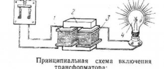
Installation of a three-phase electric meter
Although there are no particular difficulties in installing an electric meter, it is better for this work to be carried out by qualified specialists. Let's consider the installation of a three-phase electric meter with measuring transformers using the Mercury meter as an example. This meter model is one of the most common in our country.
Before proceeding with the installation of the electric meter, it is recommended to install the input circuit breaker. The presence of such a circuit breaker will help to carry out various repair or maintenance work more safely and quickly. Next, the Mercury meter and current transformers are installed directly. Then the wires are installed on the terminal block of the meter in accordance with the connection diagram. By turning on the circuit breaker, the functionality of the meter is checked using the electricity meter.
Old-generation electricity meters such as Mercury with current transformers are now being replaced by more advanced and efficient means of electricity metering. Three-phase meters of the new generation Mercury can be programmed for different operating modes, change the tariff plan and even transmit electricity readings remotely.
Every electricity consumer is required to have a metering device that allows them to control the consumption of electricity consumed. Electric meters differ in appearance, connection method and have different loads. Three-phase devices are connected via current transformers, which convert the current to optimal values at which the device can operate normally.