LM317 is an adjustable voltage stabilizer. It can be used to create various power supplies. It can be the basis for a current stabilizer, charger, laboratory power supply and even an audio amplifier. In order to use it, it is enough to connect it to one of the wiring diagrams indicated below.
This microcircuit is one of the most popular in the world - all because of the simplicity of its design and operation, its low cost and reliability. The latter is ensured by the presence of protection for short circuit of the terminals and overheating of the microcircuit. LM317 does not require many components as a harness. The microcircuit gained the greatest popularity among radio amateurs.
LM317 regulates voltage linearly, which is its advantage over switching converters. The microcircuit is sold in several housing options, the most popular is the LM317T version in the TO-220 housing. It was developed by Bob Dobkin in 1976 while he was working at National Semiconductor, and has been a hit in ham radio circles ever since.
LM317 circuit
The entire internal structure of the stabilizer can be seen on its diagram, taken in the datasheet. It shows three pins of the circuit: input (power is supplied to this input), regulation and output. At the adjustment pin, the signal voltage is first reduced by a one-way limiter to a stable 1.25V and serves as a reference source, and the current, along with the supply current, goes to a comparator based on an operational amplifier.
Also in the diagram you can see an output stage based on a bipolar transistor, which amplifies the current, and a protection unit against overheating and overcurrent.
To the right of the protection unit there is a current sensor, a drop in which is monitored by the protection in order to prevent damage from short circuits.
Characteristics of LM317
- Maximum input voltage LM317 – 40V
- LM317 output voltage range – 1.2-37V
- Maximum output current for LM317 – 1.5A
- The reference voltage of the microcircuit is 0.1-1.3V
- Minimum load current – 3.5mA
- Output voltage error – 0.1%
- Power dissipation – 20W
- Operating temperature range – 0-125C
- Storage temperature range – -65-150C
- Storage temperature range – -65-150°C
Online calculator LM317
Below is an online calculator for calculating a voltage stabilizer based on LM317. In the first case, based on the required output voltage and the resistance of resistor R1, resistor R2 is calculated. In the second case, knowing the resistances of both resistors (R1 and R2), you can calculate the voltage at the output of the stabilizer.
For a calculator for calculating the current stabilizer on LM317, see here.
Types of LM317
The microcircuit is sold in several housing options, depending on the need for size, load and connection, as well as the type of circuit installation - everyone can choose the option that suits them best.
The most popular is the LM317T in a TO-220 1.5 Ampere package. This is considered a universal option, as it can be used in surface-mounted as well as surface-mounted applications. A radiator in such a case allows you to remove excess heat and experience more severe loads than its counterparts, and if necessary, it can be attached to a larger radiator.
What is the LM317 chip?
The microcircuit is a linear voltage stabilizer, the output value of which can be set within certain limits or quickly adjusted. Available in several housing options with three terminals. The output voltage range is the same for all options, but the maximum current may vary.
| Designation | Maximum current, A | Frame |
| LM317T | 1,5 | TO-220 |
| LM317LZ | 0,1 | TO-92 |
| LM317P | 1,5 | ISOWAT-220 |
| LM317D2T | 1,5 | D2PAK |
| LM317K | 0,1 | TO-3 |
| LM317LD | 1,5 | SO-8 |
LM317 connection
LM317 has the following pin configuration in different packages:
The minimum connection diagram consists of two resistance resistors and three capacitors connected according to the diagram. In accordance with the resistance characteristics, the output voltage will be determined.
The LM317 has two main parameters: its reference voltage, as well as the current flowing out at the trim pin. Reference voltage (Vref) is the voltage that the stabilizer maintains across resistance R1. It is unstable and varies from batch to batch by an average of 0.1V, so for calculations it is better to keep in mind the average value of 1.25V. For serious projects, it is worth measuring it for each instance used. Accordingly, following the diagram, if we close resistor R2, then at the output we will get a reference voltage of 1.25V, and with an increase in the voltage at R2, the output voltage will also increase. Thus, LM317 constantly compares the output voltage through a resistive divider with the reference, therefore, by changing the resistance, we change the output voltage.
The current flowing out at the adjustment (Iadj) is parasitic. According to manufacturers, it ranges from 50 to 100 μA, but in reality it can reach 500 μA. Because of this, for stability of the output voltage, the resistance of R1 should not be higher than 240 Ohms, so that a current of less than 5 mA does not pass through the divider.
All you need is to substitute your R1 value into this formula R2=R1*((Uo/Uref)-1).
Also, don't forget about cooling. The greater the difference between the input and output current, the more the stabilizer will heat up, which will lead to problems with its operation. The parameters described by the manufacturer can only be achieved using additional cooling in the form of a radiator.
Specifications
It should be noted that all parameters were measured in the laboratory at a temperature of +25°C. And so, for the LM317T stabilizer the characteristics are equal:
- voltage range at the stabilizer output is from 1.25 to 37 V;
- output voltage instability – 0.1%;
- reference voltage VREF from 1.2 to 1.3 V;
- Maximum difference between input and output voltage Vi - Vo = 40 V;
- output current IO = 1.5 A;
- adjustable IADJ output current from 50 to 100 μA;
- thermal resistance crystal-air Rthj-amb = 65 °C/W;
- thermal resistance crystal-case Rthj-case = 5 °C/W;
- operating temperature of the junction TOPR = 0 ... +125 °C;
- storage temperature range TSTG = -65 ... +150 °C.
Typical LM317 circuits
As stated, the LM317 is used to create regulated and unregulated power supplies, however, it can also be used as the basis of a current regulator when creating LED drivers that maintain current in the circuit regardless of the input voltage. The applications described in the datasheet alone are enough to fill a separate book, so we will analyze several of the most popular circuits based on this stabilizer.
Adjustable power supply (1.2-37V)
All that is needed to create it is to replace R2 with a variable resistor, and also add a transformer with a diode bridge to the input. When using it, it is worth considering that the microcircuit has a reference voltage of 1.25V, so it will be minimal for this circuit.
Adjustable power supply (0-37V)
If you need full regulation from 0V, then circuit manufacturers suggest connecting a 10V negative voltage source to the circuit.
You can wind an additional coil on the power supply transformer and connect its leads after the diode bridge as follows:
Or you can use a negative voltage source that will be powered from the main winding.
Thus, you will get a simple laboratory power supply.
LED Driver (Current Stabilizer)
With this circuit you can power fairly powerful LEDs and LED strips. All you need is to know the current consumed and, based on it, select the resistance using the formula.
It uses the same principle as the simplest circuit, but instead of a resistive divider, a current sensor is installed. The more current the load consumes at the output, the greater the voltage drop will be observed across the sensor. It is monitored by the IC and it increases or decreases the voltage to maintain a stable current. Even in the event of a short circuit, the current will remain at the stable level that was set.
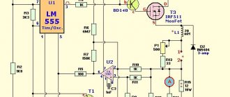
Charger
The circuit of this charger is taken from the datasheet and has an output voltage of 6V with a limit of 0.6A. By changing the resistance of resistors R1 and R2, it is possible to adjust the voltage to suit your needs, and with the help of resistor R3 - the current. It is suitable for powering batteries of phones, tools and household appliances.
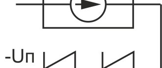
AC voltage regulation
Since two LM317 can regulate not only positive, but also negative sine wave oscillations, they can be used to create an AC regulator. You can see that the circuit is quite simple and does not require many components:
Examples of application of the LM317 stabilizer (connection circuits)
Current stabilizer
This current stabilizer can be used in circuits of various battery chargers or regulated power supplies. The standard charger circuit is shown below.
This connection circuit uses a direct current charging method. As can be seen from the diagram, the charge current depends on the resistance of resistor R1. The value of this resistance ranges from 0.8 Ohm to 120 Ohm, which corresponds to a charging current from 10 mA to 1.56 A:
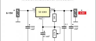
5 Volt power supply with electronic switching
Below is a diagram of a 15 volt power supply with soft start. The required smoothness of switching on the stabilizer is set by the capacitance of capacitor C2:
Adjustable voltage regulator on LM317
Switching circuit with adjustable output voltage
How to test LM317?
Unlike transistors, this microcircuit cannot be checked with a multimeter. This method does not in any way guarantee correct operation due to the large number of internal elements not connected to the terminals. Therefore, if one of them fails, then checking it with a multimeter will be problematic. The easiest way to test the operation of the LM317 is to create a simple stand on a breadboard, and it can be powered only by a battery.
This way, you can quickly verify that an item is in full working order, even if you need to check several pieces.
Application of LM317
The diagrams given above are only a small part, the basis, compared to what can be done with this stabilizer. It can be used in almost all circuits that require a constant power supply of up to 40 V. Here are some applications described in the official technical document of this chip:
- Personal computers
- Digital cameras
- ECG
- Internet switches
- Biometric sensors
- Electric motor drivers
- Portable chargers
- PoE
- RFID readers
- Appliances
- X-ray machines
As you can see, even the manufacturer himself expects the widest possible use of this element, to say nothing of home-made manufacturers who are ready to present the most unusual circuits using LM317.
Increasing the maximum output current
There are two ways to increase the maximum output current. If you need to get more than 1.5A, then you can either connect several chips in parallel, or connect a power transistor.
In the first case, it is enough to connect resistors with low resistance to the output of the stabilizers. They are needed to equalize currents.
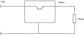
However, it is not always rational to use several chips. Therefore, a transistor comes to our aid. In this case, it will be enough to add it and a resistor as a harness to it.
If the load draws a small current, it will pass through the chip without affecting the transistor. And when it increases, almost all the current will pass through the transistor, leaving a small part of it for the stabilizer. But when using this circuit, there is internal protection inside the LM317 from short circuit.
Current stabilizer for lm317
The current at the output of the power supply may increase due to a decrease in the load resistance (a simple example, a short circuit), and a change in the load current occurs due to a change in the supply voltage. The current stabilizer on lm317 ensures current stability (current limitation) at the output in the cases described above.
This stabilizer can be used in power supply circuits for LEDs, chargers, laboratory power supplies, and so on.
If, for example, we consider LEDs, then it is necessary to take into account the fact that for them it is necessary to limit the current, not the voltage. You can apply 12V to the crystal and it will not burn out, provided that the current is limited to the rated value (depending on the marking and type of LED).
Main technical characteristics of LM317
Maximum output current 1.5A
Maximum input voltage 40V
Output voltage from 1.2V to 37V
More detailed characteristics and graphs can be found in the datasheet for the stabilizer.
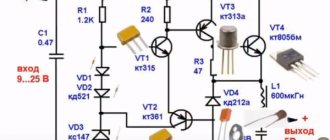
Current stabilizer circuit for lm317
The advantage of this stabilizer is that it is linear and does not introduce high-frequency interference, for example, like some switching stabilizers. The downside is the low efficiency (due to its linearity), and therefore significant heating of the chip crystal occurs. As you already understand, the microcircuit must be provided with a good heatsink.
Resistor R1 is responsible for the amount of stabilization (limiting) current. Using this resistor, you can set the stabilization current, for example, 100mA, then even with a short circuit, a current of 100mA will flow at the output of the circuit.
The resistance of resistor R1 is calculated by the formula:
R1=1.2/Iload
Initially, it is necessary to determine the amount of stabilization current. For example, I need to limit the current consumption of LEDs to 100mA. Then,
R1=1.2/0.1A=12 Ohm.
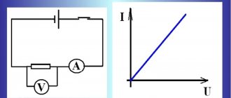
That is, to limit the current to 0.1A, it is necessary to install resistor R1 = 12 Ohms. Let's check it on hardware... To test it, I assembled the circuit on a breadboard. I was too lazy to look for a 12 Ohm resistor, so I connected two 22 Ohm ones in parallel (we had them on hand).
I set the idle voltage to 12V (you can set it to any voltage). After which, I shorted the output to ground, and the LM317 stabilizer limited the current to 0.1A. The calculations were confirmed.
As the voltage increases or decreases, the current remains stable.
The resistor can be soldered to the terminals of the microcircuit, but do not forget that the entire load current flows through the resistor, so at high currents a higher power resistor is needed.
If you use this current stabilizer on LM317 in a laboratory power supply, then you need to install a wire-type variable resistor; a simple variable resistor will not withstand the load currents flowing through it.
For the lazy, I present a table of resistor R1 values depending on the required stabilization current.
| Current | R1 (standard) |
| 0.025 | 51 Ohm |
| 0.05 | 24 ohm |
| 0.075 | 16 ohm |
| 0.1 | 13 ohm |
| 0.15 | 8.2 Ohm |
| 0.2 | 6.2 Ohm |
| 0.25 | 5.1 Ohm |
| 0.3 | 4.3 Ohm |
| 0.35 | 3.6 Ohm |
| 0.4 | 3 Ohm |
| 0.45 | 2.7 Ohm |
| 0.5 | 2.4 Ohm |
| 0.55 | 2.2 Ohm |
| 0.6 | 2 Ohm |
| 0.65 | 2 Ohm |
| 0.7 | 1.8 Ohm |
| 0.75 | 1.6 Ohm |
| 0.8 | 1.6 Ohm |
| 0.85 | 1.5 Ohm |
| 0.9 | 1.3 Ohm |
| 0.95 | 1.3 Ohm |
| 1 | 1.3 Ohm |
Thus, using a biscuit switch and several resistors, you can assemble an adjustable current stabilizer circuit with fixed values.
Datasheet for LM317
Analogs LM317
What to do if it is not possible to use LM317? You can use its analogues. The twin brothers of this component are UPC317, GL317, ECG1900 and SG317. The domestic analogue is KP142EH12A, and there is also a KP142EN12 with a fixed voltage.
If the LM317 is not enough power for your project, then you can use more powerful options:
- LM350AT and LM350T – maximum output current 3A and power 25W
- LM350K – current 3 A and power 30 W
- LM338T and LM338K – current 5 A
All these microcircuits have the same pins, so the circuits do not have to be changed in any way.
Main characteristics of linear voltage stabilizer LM317
The datasheets for the LM317 stabilizer contain complete technical information, which can be found by studying the specification. Below are the parameters, non-compliance with which is most critical and, if used incorrectly, the microcircuit may fail. First of all, this is the maximum operating current. It is given in the previous section for different types of execution. It should be added that to obtain the highest current of 1.5 A, the microcircuit must be installed on a heat sink.
The maximum voltage at the output of a regulator built on the basis of LM317 can be no more than 40 V. If this is not enough, you need to choose a high-voltage analogue of the stabilizer.
The minimum output voltage is 1.25 V. With this design of the circuit, you can get less, but the overload protection will work. This is not the best option - such protection should work against exceeding the output current, as it works in other integrated stabilizers. Therefore, in practice, it is impossible to obtain a regulator that operates from zero when a negative bias is applied to the Adjust pin.
The minimum input voltage value is not indicated in the datasheet, but can be determined from the following considerations:
- minimum output voltage – 1.25 V;
- the minimum voltage drop for Uout = 37 V is equal to three volts, it is logical to assume that for the minimum output it should be no less;
Safe operation of LM317
It is worth remembering the operational characteristics of the radio component and not using it in critical conditions. The power dissipation according to official information is 20 W, and the difference between the input and output voltages should not exceed 40 V. During soldering, the temperature should not exceed 260 C. It can be used at temperatures from 0C to 125C, and stored from -65C to 150C. All these are officially declared characteristics; in reality, they may differ from instance to instance and be underestimated.
You should not use the element at the maximum and minimum indicated values. With such operation, the level of stability and reliability will drop significantly. It is also highly advisable to use a radiator to remove heat, since otherwise the stated characteristics may not coincide with the real ones.