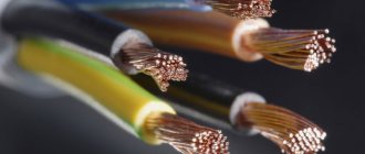
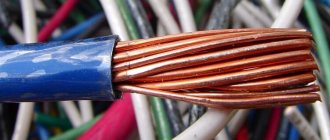
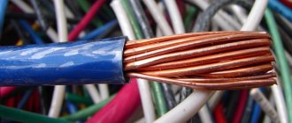
To make the work of electricians easier, the production of cable insulation is subject to certain color marking standards. When connecting a multi-core cable, you can identify the core by the color of the polymer sheath and understand which contact it should be connected to.
Different colors of electrical wires, established by GOST provisions, help speed up the installation process and ensure electrical safety. Agree, understanding color coding is useful to every home craftsman.
We suggest you understand the symbols of electrical wiring, learn GOST standards and learn to read the letter codes of wires on diagrams. In addition, we will tell you how to check the compliance of the connected core with its intended purpose using an indicator screwdriver or a multimeter.
Features of core colors
To avoid errors, the PUE requirements describe the colors of all main electrical wires. If the commissioning work was carried out by an experienced electrician who follows the rules of the Electrical Installation Code and the relevant GOSTs, during independent repairs you will not need either an indicator screwdriver or other devices that determine the purpose of a particular core.
Color marking in electrical equipment according to GOST
Additional markings
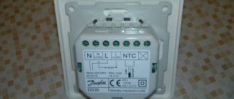
In addition to letters, cables are marked with numbers. They serve to indicate the voltage that is working for the wire (if absent, take it as 220 V), the number of conductors, the nominal cross-section of the conductor, and the nominal cross-section of the screen.
After the digital encoding there is a designation of technical conditions (TS). The cable may be marked GOST or TU. This means that either the wire was produced in accordance with all norms and rules, complies with state standards, or only fits the specified technical conditions.
Grounding
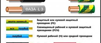
The yellow-green wire is grounding. In circuit diagrams, grounding conductors are marked with the letters PE. In some older houses there are PEN wires in which the grounding is combined with the neutral conductor. If the cable was pulled according to the rules, wires with blue insulation were chosen, and only the ends and places of twists were yellow-green (thermal tubes were put on them). The thickness of the “zero” and grounding may be different. Often the thickness of these two conductors is less than the thickness of the phase conductor; this occurs when connecting portable devices.
When it comes to laying electrical wiring in multi-storey buildings and industrial premises, the norms of PUE and GOST 18714-81 come into force, requiring the mandatory installation of protective grounding. Grounding must have minimal resistance to compensate for the consequences of faults on the line and prevent harm to human health. That is, compliance with the standards for color marking of PUE wires is of paramount importance.
Electrical safety
The human eye does not see the electric field, and therefore is not able to detect live wires. Touching them is extremely dangerous and can be fatal. To protect people and reduce risks to the system, standards were adopted (GOST R 50462-92).
Oil-impregnated paper and plastic insulation are the most common in Russia. The first is used in an aggressive environment because of its ability to regenerate, that is, restore its previous properties. Today, PVC insulation is gaining great popularity.
"Phase"
The color of the phase is what is of paramount importance for an electrician: handling conductive conductors requires care and knowledge. The slightest touch of the phase can lead to injury. There are many colors for phase wires marked in the form of the letter L in electrical wiring; the ban only applies to the use of blue, yellow and green colors. If the cable is three-phase, the serial number of the core is added to the letter L.
When a single-phase circuit is separated from a three-phase one, electricians use cables with strictly the same colors, monitoring the color of the phase and zero in the wire. Before starting work, they determine for themselves how the different wires will be connected, and then follow the chosen color. Sometimes thermal casings are fused onto them or several turns of colored appropriate electrical tape are wound.
According to GOST:
- black phase wires are used in power circuits operating with direct and alternating current;
- red color - used in control circuits designed for alternating current;
- with orange color - found in interlock control circuits powered from external sources.
Arrangement of busbars in electrical installations with voltage up to 1 kV
In five- and four-wire three-phase alternating current circuits in electrical installations with voltages up to 1 kV, the busbar arrangement should be as follows:
- when positioned horizontally:
- one below the other: from top to bottom ABCN-PE (PEN);
- one after another: the most distant bus A, then the BCN phases, the closest to the service corridor - PE (PEN);
- in a vertical position:
- from left to right ABCN-PE (PEN) or
- the most distant bus A, then the BCN phases, the closest to the service corridor - PE (PEN);
- branches from busbars, if you look at the busbars from the service corridor:
- when positioned horizontally: from left to right ABCN-PE (PEN);
- for vertical placement: ABCN-PE (PEN) from top to bottom.
With direct current, the busbars should be located:
- busbars with a vertical arrangement: upper M, middle (-), lower (+);
- busbars with a horizontal arrangement: the most distant M, middle (-) and closest (+), when looking at the busbars from the service corridor;
- branches from busbars: left busbar M, middle (-), right (+), if you look at the busbars from the service corridor.
How to determine the purpose of a wire - neutral or ground?
LN marking in electrical engineering is not always observed in old buildings, so the question arises of independently distinguishing between the neutral wire and the ground wire. When the circuit is closed, an electric current passes through the “zero”. The grounding wire has only a protective function, and in “normal” mode no current flows through it.
You can find out whether it is “zero” or “ground” like this:
- Use an ohmmeter, first turning off the voltage between the measurement points. The resistance on the ground wire will not exceed 4 ohms.
- Use a voltmeter and sequentially measure the voltage between the “phase” and other wires (the method is suitable for three-core cables). The ground wire will give the greatest value.
- If the colors of the “phase”, “zero” and “ground” wires are unknown, and you need to find out the voltage between the ground wire and some known grounded object (for example, a heating radiator), a voltmeter is also useful. True, when connecting the “earth” and a grounded object, it will not show anything. But a small voltage will be reflected in its indicator if you do the same with the “zero” wire.
In a two-core cable there will always be only a phase and neutral wire.
How to mark a wire with two cores
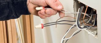
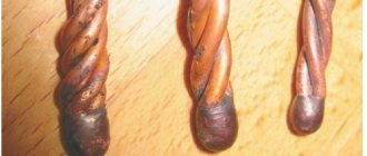
If all the wires in the cable have the same insulation, and the electrical appliance is already connected to the network, the craftsmen use indicator screwdrivers. The latter glow when the metal part touches the phase wire. To mark a two-core cable, in addition to such a screwdriver, you will need thermal casings or multi-colored electrical tape. Colors will be marked only at the joints - it is not necessary to wrap the core with colored tubes or electrical tape along its entire length.
Probe screwdriver-indicator
Phase wires can be marked with any colors except blue, yellow and green. If a two-core cable is connected to a single-phase network, it is customary to secretly mark the phase wire in red.
How to mark a wire with three cores
What color is the ground wire in a three-wire wire? If the answer to the question cannot be determined immediately, all the insulation on the wires is the same color, a multimeter will help out. The device is set to alternating current, and the master sequentially touches with both probes first the phase wire, then the remaining wires, memorizing the indicators. Touching phase and zero will produce a higher voltage than touching phase and ground.
What color is the ground wire? It has a yellow-green color. It is this kind of thermal casing or electrical tape that should be used to mark the “ground” in a three-core cable. On the “zero” you should wind a blue tape, on the phase - not blue or yellow-green thermal cambric.
Letter designation of phase, zero and ground
The use of different colors of wires in electrical wiring is a convenient and logical measure that simplifies repair and installation work. If the house has wires with multi-colored conductors, during repairs you will not have to waste time “ringing” each of them, and, for example, a broken phase conductor will be detected quickly. The presence of a letter designation of phase and zero is also important, but working with letters and numbers is still longer than with color: just look at the cable and the purpose of the cores immediately becomes clear.
Checking the correct connection
Unfortunately, not all electricians strictly follow the standards and make mistakes in choosing a conductor when making connections. Therefore, when hanging a chandelier, installing a socket or other electrical installation device, it is better to additionally check whether the insulation of each core corresponds to its purpose.
Mandatory checking of the neutral or phase is dictated by safety standards and the instinct of self-preservation: if you accidentally mix up the contacts during installation, you can get an unpleasant injury - an electrical burn
For identification, installers use two methods: the first is checking with an indicator screwdriver, the second is using a tester or multimeter. The phase is usually determined with a screwdriver, and neutral and zero are determined with measuring instruments.
How to use the indicator?
Even such simple devices as indicator screwdrivers are different. Some of them are equipped with a small button, others are triggered automatically when a metal rod and a current-carrying conductor or contact are connected.
But all models without exception have a built-in LED that lights up under voltage.
The indicator screwdriver is preferred by amateurs who do not have special qualifications. Professional electricians value accuracy, so they always have a tester with them.
A screwdriver is a convenient tool for identifying phase conductors. To find out whether the wire is working, use the metal blade of a screwdriver to gently touch the exposed wire.
If the LED lights up, the wire is energized. The absence of a signal indicates that it is ground or zero.
When using the indicator, you must adhere to the safety rules. Even if the screwdriver handle is insulated, it is recommended to wear protective gloves (with a rubberized inner layer), as when working with electricians in general.
The verification procedure is performed with one hand, therefore, the other is free. It is better to also use it - for example, to fix wires. But it is strictly forbidden to touch the exposed parts of conductors or metal objects located nearby (pipes, fittings) with your second hand.
Rules for using the tester
An electrician's kit always includes a tester or multimeter. He has to work with the connection of conductors in electrical installations indoors and when assembling an electrical panel. If the wiring was installed a long time ago, marking the wires by color can be neglected.
Even if the insulation colors seem to be consistent, it is not a fact that they are connected according to all the rules.
Using the tester, you can find out not only the likelihood of connecting conductors to the electrical network, but also some parameters: current, resistance, voltage. Using a multimeter you can test diodes, check transistors, determine inductance
Before taking measurements, you should study the instructions that accompany all measuring instruments.
The procedure is approximately as follows:
- we set a value that is obviously higher than the expected voltage, for example, 260 V;
- connect the probes to the required sockets;
- we touch two conductors with probes - presumably phase and neutral;
- repeat the procedure with another pair of conductors.
The combination of phase-zero cores should produce a result close to 220 V. It will always be higher than the phase-ground pair.
There are both digital, modern instruments on sale, as well as outdated ones, with arrows and value scales. It is more convenient to use digital ones. Before installing electrical devices yourself, we recommend learning how to use either an indicator screwdriver or a multimeter - you should not rely only on the color of the wires.
The ability to use a multimeter will be useful for a home handyman to check the voltage in an outlet. Detailed instructions for using the tester are given in this article.