One of the first converter circuits for powering a three-phase motor was published in Radio magazine No. 11, 1999. The developer of the scheme, M. Mukhin, was a 10th grade student at that time and was involved in a radio club.
The converter was intended to power a miniature three-phase motor DID-5TA, which was used in a machine for drilling printed circuit boards. It should be noted that the operating frequency of this motor is 400Hz, and the supply voltage is 27V. In addition, the middle point of the motor (when connecting the windings in a star) is brought out, which made it possible to simplify the circuit extremely: only three output signals were needed, and only one output switch was required for each phase. The generator circuit is shown in Figure 1.
As can be seen from the diagram, the converter consists of three parts: a three-phase sequence pulse generator on DD1...DD3 microcircuits, three switches on composite transistors (VT1...VT6) and the electric motor M1 itself.
Figure 2 shows the timing diagrams of the pulses generated by the generator-shaper. The master oscillator is made on the DD1 chip. Using resistor R2, you can set the required engine speed, and also change it within certain limits. More detailed information about the scheme can be found in the above magazine. It should be noted that according to modern terminology, such generator-shapers are called controllers.
Figure 2. Generator pulse timing diagrams.
Based on the considered controller by A. Dubrovsky from Novopolotsk, Vitebsk region. The design of a variable frequency drive for a motor powered by a 220V AC network was developed. The device diagram was published in Radio magazine in 2001. No. 4.
In this circuit, practically without changes, the controller just discussed according to M. Mukhin’s circuit is used. The output signals from elements DD3.2, DD3.3 and DD3.4 are used to control the output switches A1, A2, and A3, to which the electric motor is connected. The diagram shows key A1 in full, the rest are identical. The complete diagram of the device is shown in Figure 3.
Connecting the motor to the output of a three-phase inverter
To familiarize yourself with connecting the motor to the output switches, it is worth considering the simplified diagram shown in Figure 4.
The figure shows an electric motor M controlled by keys V1...V6. To simplify the circuit, semiconductor elements are shown as mechanical contacts. The electric motor is powered by a constant voltage Ud received from the rectifier (not shown in the figure). In this case, the keys V1, V3, V5 are called upper, and the keys V2, V4, V6 are called lower.
It is quite obvious that opening the upper and lower keys at the same time, namely in pairs V1&V6, V3&V6, V5&V2 is completely unacceptable: a short circuit will occur. Therefore, for the normal operation of such a key circuit, it is necessary that by the time the lower key is opened, the upper key has already been closed. For this purpose, control controllers create a pause, often called a “dead zone”.
The length of this pause is such as to ensure guaranteed closure of the power transistors. If this pause is not sufficient, then it is possible to briefly open the upper and lower keys simultaneously. This causes the output transistors to heat up, often leading to their failure. This situation is called through currents.
Let's return to the circuit shown in Figure 3. In this case, the upper keys are 1VT3 transistors, and the lower ones are 1VT6. It is easy to see that the lower keys are galvanically connected to the control device and to each other. Therefore, the control signal from output 3 of element DD3.2 through resistors 1R1 and 1R3 is supplied directly to the base of the composite transistor 1VT4…1VT5. This composite transistor is nothing more than a lower switch driver. In exactly the same way, elements DD3, DD4 control the composite transistors of the lower key drivers of channels A2 and A3. All three channels are powered from the same rectifier on the VD2 diode bridge.
The upper switches do not have a galvanic connection with the common wire and the control device, so to control them, in addition to the driver on the composite transistor 1VT1...1VT2, it was necessary to install an additional 1U1 optocoupler in each channel. The output transistor of the optocoupler in this circuit also performs the function of an additional inverter: when the output of element 3 of DD3.2 is high, the transistor of the upper switch 1VT3 is open.
To power each upper switch driver, a separate rectifier 1VD1, 1C1 is used. Each rectifier is powered by an individual winding of the transformer, which can be considered as a disadvantage of the circuit.
Capacitor 1C2 provides a switching delay of about 100 microseconds, the same amount is provided by optocoupler 1U1, thereby forming the above-mentioned “dead zone”.
Is frequency regulation enough?
As the frequency of the AC supply voltage decreases, the inductive reactance of the motor windings decreases (just remember the formula for inductive reactance), which leads to an increase in the current through the windings, and, as a consequence, to overheating of the windings. The stator magnetic circuit is also saturated. To avoid these negative consequences, when the frequency decreases, the effective value of the voltage on the motor windings must also be reduced.
One of the ways to solve the problem in amateur frequency generators was to regulate this most effective value using an LATR, the moving contact of which had a mechanical connection with a variable resistor of the frequency regulator. This method was recommended in the article by S. Kalugin “Refinement of the speed controller of three-phase asynchronous motors.” Radio magazine 2002, no. 3, p. 31.
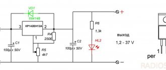
In amateur conditions, the mechanical unit turned out to be difficult to manufacture and, most importantly, unreliable. A simpler and more reliable method of using an autotransformer was proposed by E. Muradkhanyan from Yerevan in the magazine “Radio” No. 12 2004. The diagram of this device is shown in Figures 5 and 6.
The 220V network voltage is supplied to the autotransformer T1, and from its moving contact to the rectifier bridge VD1 with filter C1, L1, C2. The output of the filter produces a variable constant voltage Ureg, which is used to power the motor itself.
The voltage Ureg through resistor R1 is also supplied to the master oscillator DA1, made on the KR1006VI1 microcircuit (imported version NE555). This connection turns a conventional square wave generator into a VCO (voltage controlled oscillator). Therefore, as the voltage Ureg increases, the frequency of generator DA1 also increases, which leads to an increase in engine speed. As the voltage Ureg decreases, the frequency of the master generator also decreases proportionally, which avoids overheating of the windings and oversaturation of the stator magnetic circuit.
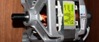
Commutator motor operation
For someone who understands the principles of operation of a commutator engine, starting will not seem like a difficult task.
Let's take a quick look to understand the essence of the problem. The above figure schematically shows: The principle of operation of a commutator motor
- The design of a commutator motor from stator windings (rectangle with oblique lines), commutator (narrow orange rectangles), brushes (vertical gray rectangles).
- The electrical connection diagram is for direct current. The blue line shows the minus (north pole), the red line shows the plus (south pole).
- Along the horizontal row, cross sections of the rotor and stator are given (schematically). For simplicity, the stationary part of the motor is represented by two poles, although in reality there are more. The northern one is marked in blue, the southern one is marked in red. If you disassemble the electric motor, you can observe a similar picture with your own eyes. The cut of the rotor resembles the crossbar of a magnetron.
How it works. The engine manifold is formed by sections, which can be seen schematically in the figure. The copper drum is divided by insulating crossbars into even rows of lamellas. Each section is equipped with leads on strictly opposite sides of the circle. Accordingly, two brushes are suitable. One for each side. One section receives power, and a field appears in the coil. Let's see where this leads.
- In the upper part of the figure we see the direct connection of the stator and rotor. The field is distributed so that the shaft begins to rotate clockwise. Charges of the same signs on the stator and rotor repel, while charges of opposite signs attract. The section will travel a certain distance in a circle, the brushes are transferred to the next one, and it begins to work. The cycle is repeated as long as the supply voltage is supplied.
- By turning on the brushes towards the stator, we change the distribution of charges on the rotor to the opposite one. See what the reverse leads to (lower part of the picture). The motor shaft rotates counterclockwise. As before, charges of the same signs attract, charges of different signs repel.
To change the direction of movement of the washing machine motor, special contactors (power relays) are used. If necessary, the rotor is turned on towards the stator, a reverse is formed
One thing is important: if the shaft does not rotate correctly, change the direction in which the windings are turned on. We’ll tell you how to do it later.
Manufacturing a soft start socket
The most important requirement for such an outlet is its mobility. Therefore, you will need a carrier.
With its help, you can smoothly launch the tool anywhere - in the garage, at the dacha, during the construction of your house in different areas of the construction site.
The first step is to disassemble the carrier.
The main power wires in it can be either soldered or connected to screw terminals.
Depending on this, your additional outlet will also be connected. This should be an additional socket near the carrying case in order to be able to simultaneously connect the instrument in different modes.
By the way, if you mistakenly turn on an angle grinder or circular saw that has a factory built-in soft start into an outlet that is also equipped with such a soft starter, then surprisingly everything will work. The only thing is that there will be a delay in starting the saw or turning the disk for a couple of seconds, which is not very convenient to use and can be puzzling if you don’t get used to it.
Here are real tests of such a connection, carried out by one master from YouTube BaRmAgLoT777. His comment after such tests on a Dremel type engraver, a Bosch drill, a Makita router, and an Interskol circular saw:
Next, to assemble the socket, take a stranded copper wire with a cross-section of 2.5 mm2 and strip its ends.
Then you need to tin the contact pad on the carrier where this wire will be soldered.
Securely solder the cable cores to these pads.
Carefully lay out the wires and close the extension cord.
Take a square external socket for installation on the outer surface of the walls, and try on a soft starter unit in its housing. Since it has compact rectangular dimensions, it should fit there without any problems.
Mount and secure the socket body on the same platform as the extension cord.
The PP block is connected to the gap of any wire, phase or neutral. Do not confuse it, phase and zero are not supplied to it at the same time, i.e. 220V.
It is installed on one of the wires.
Also for this BPP, there is no difference on which side to make the entrance and on which side to make the exit. The twists are soldered and insulated with heat shrink.
After that, all the insides of the socket are assembled into a housing and all that remains is to close the entire structure with a lid.
At this point, the entire reworking of the carrying case and the manufacture of the socket can be considered complete. It will take you no more than 15 minutes.
Control principle
When the rotation speed of the motor shaft is set by a resistor in output circuit 5, a sequence of pulses is formed at the output to unlock the triac by a certain angle. The speed of rotation is monitored by a tachogenerator, which occurs in digital format. The driver converts the received pulses into an analog voltage, which is why the shaft speed is stabilized at a single value, regardless of the load. If the voltage from the tachogenerator changes, the internal regulator will increase the level of the output control signal of the triac, which will lead to an increase in speed.
The microcircuit can control two linear accelerations, allowing you to achieve the dynamics required from the engine. One of them is installed on the Ramp 6 output of the circuit. This regulator is used by washing machine manufacturers themselves, so it has all the advantages to be used for domestic purposes. This is ensured by the presence of the following blocks:
- Voltage stabilizer to ensure normal operation of the control circuit. It is implemented at pins 9, 10.
- Rotation speed control circuit. Implemented using MS pins 4, 11, 12. If necessary, the controller can be switched to an analog sensor, then pins 8 and 12 are combined.
- Starting impulse block. It is implemented at pins 1, 2, 13, 14, 15. It adjusts the duration of control pulses, delays, generates them from a constant voltage and calibrates.
- Sawtooth voltage generation device. Pins 5, 6 and 7. It is used to control the speed according to the set value.
- Control amplifier circuit. Pin 16. Allows you to adjust the difference between the set and actual speed.
- Current limiting device at pin 3. When the voltage on it increases, the triggering angle of the triac decreases.
The use of such a circuit ensures full control of the commutator motor in any mode. Thanks to forced acceleration control, it is possible to achieve the required acceleration speed to a given rotation speed. Such a regulator can be used for all modern washing machine motors used for other purposes.
https://youtube.com/watch?v=yLHAaZTr0hQ
Source
What is this function, principle of operation, electrical circuit, advantages of an angle grinder with a regulator
An angle grinder that is not equipped with a speed control device operates exclusively at maximum rotation speed. Equipped with this option, it allows you to reduce the rotation speed to a value that allows you to efficiently process materials, which is impossible at maximum mode.
The electronic unit of the speed controller is based on a modified dimmer principle, where the power is changed by manually changing the value of a variable resistor. With the help of electronic control of the current strength, the torque is maintained on the working shaft of the spindle, ensuring the functionality of the angle grinder. The main working elements of such a circuit can be either a semiconductor device triac or a more advanced version with an integrated circuit.
Connection diagram without power regulator
The electrical circuit of ordinary household angle grinders without additional options is shown in the figure:
Electrical diagram of an angle grinder. Photo source here
Here, two unconnected stator windings are connected to a voltage source (household network) through a switch, which has a manual start button in its design. Next, each of the windings is connected using special contacts to graphite brushes, which are pressed against the surface of the commutator using springs. In turn, the ends of the rotor windings are connected to the commutator lamellas, forming a closed electrical circuit.
The speed controller is connected to the open circuit between the on/off button and the stator windings when located inside the body of the angle grinder. If designed as a separate unit, it can often be located in a break in the network cable.
Frequency regulation
Special devices, frequency converters (other names: inverter, frequency converter, driver), are connected to an electrical machine. By rectifying the supply voltage, the frequency converter internally generates the required frequency and voltage values and supplies them to the electric motor.
The converter calculates the necessary parameters for blood pressure control independently, according to internal algorithms programmed by the device manufacturer.
Advantages of frequency regulation
.
- Smooth control of the electric motor rotation speed is achieved.
- Changing the speed and direction of rotation of the engine.
- Automatic maintenance of required parameters.
- Cost-effective control system.
The only drawback that you can put up with is the need to purchase a frequency converter. The prices for such devices are absolutely sky-high, and within 150 euros, you can get a converter for a 2 kW motor.
Advantages and disadvantages
To summarize, we highlight the following advantages of CLEBO A3:
- Navigation based on camera and gyroscope.
- Building a room map.
- Build quality and performance.
- Extended delivery set.
- Several operating modes + polisher mode.
- Setting up a cleaning schedule.
- Control from smartphone and remote control.
- Working with voice assistants.
- Low noise level.
The downside of the iCLEBO A3 is the poorly implemented wet cleaning function, which is just wiping the floor with a dampened cloth without electronic control
It is also important to understand that the device is controlled via Bluetooth, that is, it will not be possible to start it remotely, for example, while at work. Well, the cost of a robot vacuum cleaner at 29,900 rubles, let’s be objective, is not affordable for everyone. Otherwise, there are no complaints about this model.
Otherwise, there are no complaints about this model.
Finally, we recommend looking at the rating of the best robot vacuum cleaners with a camera:
Analogues:
- Xiaomi Mijia LDS Vacuum Cleaner
- GUTREND SENSE 410
- Roborock S6 Pure
- Ecovacs DeeBot OZMO 900
- HOBOT Legee-688
- iRobot Roomba 960
- Okami U90 Vision
Voltage regulation
Speed control in this way is associated with a change in the so-called engine slip - the difference between the rotation speed of the magnetic field created by the stationary engine stator and its moving rotor:
n1—magnetic field rotation speed
n2—rotor rotation speed
In this case, sliding energy is necessarily released - which causes the motor windings to heat up more.
This method has a small control range, approximately 2:1, and can also only be carried out downwards - that is, by reducing the supply voltage.
When regulating speed in this way, it is necessary to install oversized motors.
But despite this, this method is used quite often for low-power motors with a fan load.
In practice, various regulator circuits are used for this.
Autotransformer voltage regulation
An autotransformer is an ordinary transformer, but with one winding and taps from some of the turns. In this case, there is no galvanic isolation from the network, but in this case it is not needed, so savings are achieved due to the absence of a secondary winding.
The diagram shows autotransformer T1, switch SW1, which receives taps with different voltages, and motor M1.
The adjustment is done in steps; usually no more than 5 steps of regulation are used.
Advantages of this scheme:
- undistorted output voltage waveform (pure sine wave)
- good overload capacity of the transformer
Flaws:
- large mass and dimensions of the transformer (depending on the power of the load motor)
- all the disadvantages inherent in voltage regulation
Thyristor engine speed controller
This circuit uses keys - two thyristors connected back-to-back (the voltage is alternating, so each thyristor passes its own half-wave of voltage) or a triac.
The control circuit regulates the moment of opening and closing of the thyristors relative to the phase transition through zero; accordingly, a piece is “cut off” at the beginning or, less often, at the end of the voltage wave.
This changes the rms voltage value.
This circuit is quite widely used to regulate active loads - incandescent lamps and all kinds of heating devices (so-called dimmers).
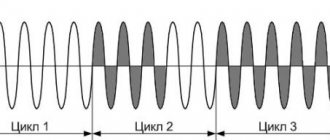
Another method of regulation is to skip half-cycles of the voltage wave, but at a network frequency of 50 Hz this will be noticeable for the motor - noise and jerking during operation.
To control motors, regulators are modified due to the characteristics of the inductive load:
- install protective LRC circuits to protect the power switch (capacitors, resistors, chokes)
- add a capacitor at the output to adjust the voltage waveform
- limit the minimum voltage regulation power - for guaranteed engine start
- use thyristors with a current several times higher than the electric motor current
Advantages of thyristor regulators:
Flaws:
- can be used for low power engines
- During operation, noise, crackling, and jerking of the engine may occur.
- when using triacs, a constant voltage is applied to the motor
- all the disadvantages of voltage regulation
It is worth noting that in most modern mid- and high-level air conditioners, the fan speed is adjusted in this way.
Transistor voltage regulator
As the manufacturer himself calls it, an electronic autotransformer or PWM regulator.
The voltage is changed using the PWM (pulse width modulation) principle, and transistors are used in the output stage - field-effect or bipolar with insulated gate (IGBT).
The output transistors are switched at a high frequency (about 50 kHz); if you change the width of the pulses and pauses between them, the resulting voltage at the load will also change. The shorter the pulse and the longer the pause between them, the lower the resulting voltage and power input.
For a motor, at a frequency of several tens of kHz, a change in the pulse width is equivalent to a change in voltage.
The output stage is the same as that of a frequency converter, only for one phase there is a diode rectifier and two transistors instead of six, and the control circuit changes the output voltage.
Advantages of an electronic autotransformer:
- Small dimensions and weight of the device
- Low cost
- Clean, undistorted current output waveform
- No hum at low speeds
- 0-10 Volt signal control
Weak sides:
- The distance from the device to the engine is no more than 5 meters (this disadvantage is eliminated when using a remote controller)
- All the disadvantages of voltage regulation
How to make a soft start circuit for an angle grinder with your own hands
The popular circuit is implemented on the basis of the KR118PM1 phase control control microcircuit, and the power part is made of triacs. Such a device is quite easy to install, does not require additional settings after assembly, and therefore, it can be made by a master without specialized education, just be able to hold a soldering iron in his hands.
Electrical circuit for adjusting soft start for an angle grinder
The proposed unit can be connected to any power tool designed for an alternating voltage of 220 volts. A separate remote power button is not required; the modified power tool is turned on with a standard key. The circuit can be installed either inside the body of the angle grinder or in the break of the power cable in a separate case.
The most practical thing is to connect the soft starter to the socket from which the power tool is powered. The input (XP1 connector) is supplied with power from a 220 volt network. A consumable socket is connected to the output (connector XS1), into which the angle grinder plug is plugged.
When the start button of the angle grinder is closed, voltage is supplied to the DA1 chip via the common power circuit. There is a smooth increase in voltage across the control capacitor. As it charges, it reaches a working value. Due to this, the thyristors in the microcircuit do not open immediately, but with a delay, the time of which is determined by the charge of the capacitor. Triac VS1, controlled by thyristors, opens with the same pause.
Watch the video with a detailed explanation of how to do it and what scheme to use
In each half-cycle of alternating voltage, the delay decreases in an arithmetic progression, as a result of which the voltage at the input to the power tool gradually increases. This effect determines the smooth start of the angle grinder engine. Consequently, the disk speed increases gradually, and the gearbox shaft does not experience inertial shock.
The time it takes for the speed to reach the operating value is determined by the capacitance of capacitor C2. The value of 47 uF ensures a smooth start in 2 seconds. With such a delay, there is no particular discomfort when starting to work with the tool, and at the same time, the power tool itself is not subject to excessive loads from a sudden start.
After turning off the angle grinder, capacitor C2 is discharged by resistor R1. At a nominal 68 kOhm, the discharge time is 3 seconds. After which the soft starter is ready for a new start cycle of the angle grinder. With a little modification, the circuit can be upgraded to an engine speed controller. To do this, resistor R1 is replaced with a variable one. By adjusting the resistance, we control the engine power by changing its speed.
Thus, in one housing it is possible to make an engine speed controller and a soft start device for a power tool.
The remaining details of the circuit work as follows:
- Resistor R2 controls the amount of current flowing through the control input of triac VS1;
- Capacitors C1 and C2 are control components of the KR118PM1 microcircuit, used in a typical switching circuit.
For simplicity and compactness of installation, resistors and capacitors are soldered directly to the legs of the microcircuit.
The VS1 triac can be anything with the following characteristics: maximum voltage up to 400 volts, minimum throughput current 25 amperes. The amount of current depends on the power of the angle grinder.
Due to the smooth start of the angle grinder, the current will not exceed the rated operating value for the selected power tool. For emergency cases, for example, a jammed angle grinder disk, a current reserve is required. Therefore, the nominal value in amperes should be doubled.
The ratings of the radio components used in the proposed electrical circuit were tested on an angle grinder with a power of 2 kW. There is a power reserve of up to 5 kW, this is due to the peculiarity of the operation of the KR118PM1 microcircuit. The scheme is working, executed many times by home craftsmen.
If you have an old angle grinder in your arsenal, don’t rush to write it off. Using a simple electrical circuit, the device can be easily upgraded by adding the function of changing the speed. Thanks to a simple regulator that you can actually assemble with your own hands in a few hours, the functionality of the device will increase significantly. By reducing the rotation speed, the grinder can be used as a grinding and sharpening machine for various types of materials. New opportunities are emerging for the use of additional attachments and accessories.
Regulator for 220 Volt motors
A self-made engine speed controller can be mounted in the tool body or made in a separate housing, which significantly improves the convenience and versatility of its use. The self-contained controller can be used as needed for various power tools.
The simplest speed controller for a commutator motor can be made with your own hands in several ways - on a printed circuit board, mounted or mounted on a circuit board.
Main elements of the scheme:
- triac BTA 16;
- dinistor DB 3;
- variable resistor 500 kOhm;
- fixed resistor 2 kOhm;
- capacitance 100 nF;
- foil PCB or circuit board;
- solder;
- rosin;
- ferric chloride;
- laser disc marker and pencil.
Cut a piece of foil PCB of the required size, sand it, degrease it and draw a diagram of the device for subsequent etching in ferric chloride.
After etching, rinse, drill holes for soldering circuit elements, tin the printed tracks and pads, and assemble the circuit.
Instead of making your own printed circuit board, you can buy a ready-made circuit board.
By installing the assembled circuit into an easy-to-use case, you will receive a 220V speed controller made by yourself.
How to connect the device to an angle grinder, options
The connection of the regulator depends on what type of device is selected. If a simple circuit is used, it is enough to mount it into the power supply channel of the power tool.
Installing a homemade board
There are no ready-made installation recipes. Anyone who decides to equip an angle grinder with a regulator places it in accordance with their goals and model of the tool. Some people insert the device into the handle of the holder, others into a special additional box on the body.
In different models, the space inside the angle grinder body may be different. Some have enough free space to install a control unit. In others, you have to take it to the surface and attach it in a different way. But the trick is that, as a rule, there is always a certain cavity in the back of the instrument. It is designed for air circulation and cooling.
Cavity at the back of the device
This is usually where the factory speed controller is located. A DIY diagram can be placed in this space. To prevent the regulator from burning out, the thyristors should be installed on the radiator.
Features of installation of the finished block
When purchasing and installing a factory regulator inside an angle grinder, most often you have to modify the body - cut a hole in it to allow the adjustment wheel to come out. But this may adversely affect the rigidity of the casing. Therefore, it is preferable to install the device outside.
The adjustment wheel changes the speed
The numbers on the adjustment wheel indicate the number of spindle revolutions. This value is not absolute, but conditional. “1” is the minimum speed, “9” is the maximum. The remaining numbers serve as a guide for regulation. The location of the wheel on the body varies. For example, on the Bosch PWS 1300–125 CE, Wortex AG 1213–1 E or Watt WWS-900 angle grinders, it is located at the base of the handle. On other models, such as the Makita 9565 CVL, the adjustment wheel is located at the end of the housing.
The connection diagram of the regulator to the angle grinder is not complicated, but sometimes it is not so easy to stretch the cables to the button, which is located at the other end of the device body. The problem can be solved by selecting the optimal wire cross-section or by placing it on the surface of the casing.
The regulator is connected according to the diagram
A good option is to install the regulator on the surface of the device or attach it to a network cable. Not everything always works out on the first try; sometimes the device has to be tested and then some adjustments made. And this is easier to do when access to its elements is open.
Attaching to the power cord
Why adjust the rotation speed of the grinder disc at all?
- When cutting metal of different thicknesses, the quality of work greatly depends on the speed of rotation of the disk. If you are cutting hard and thick material, you must maintain maximum rotation speed. When processing thin sheet metal or soft metal (for example, aluminum), high speeds will lead to melting of the edge or rapid blurring of the working surface of the disk;
- Cutting and sawing stone and tile at high speed can be dangerous. In addition, the disk, which rotates at high speeds, knocks small pieces out of the material, making the cutting surface chipped. Moreover, different speeds are selected for different types of stone. Some minerals are processed at high speeds;
- Grinding and polishing work is in principle impossible without adjusting the rotation speed. By setting the speed incorrectly, you can damage the surface, especially if it is a paint coating on a car or a material with a low melting point;
- The use of discs of different diameters automatically implies the presence of a regulator. Changing a disk Ø115 mm to Ø230 mm, the rotation speed must be reduced by almost half. And holding a grinder with a 230 mm disc rotating at a speed of 10,000 rpm is almost impossible to hold in your hands;
- Polishing of stone and concrete surfaces, depending on the type of crowns used, is carried out at different speeds. Moreover, when the rotation speed decreases, the torque should not decrease;
- When using diamond discs, it is necessary to reduce the number of revolutions, since their surface quickly fails due to overheating. Of course, if your grinder works only as a cutter for pipes, angles and profiles, you won’t need a speed controller. And with the universal and versatile use of angle grinders, it is vital.
To solve what problems is an angle grinder with speed control needed?
Angle grinder AEG 451410 WS13-125XE in operation. Photo 220Volt
The advantages of an angle grinder with a speed controller are manifested when performing the following work :
- processing plastic or thin sheets of steel and other metals without allowing the material to melt or warp;
- when processing stone or ceramic tiles, it helps to avoid chipping on the surfaces of these materials;
- The diamond cutting tool will not overheat at lower speeds and will operate longer;
- performing grinding and polishing of some materials at optimal speeds to obtain a high-quality result.
Frequency regulation
Just recently (10 years ago), there were a limited number of frequency controllers for motor speeds on the market, and they were quite expensive. The reason was that there were no cheap high-voltage power transistors and modules.
But developments in the field of solid-state electronics have made it possible to bring power IGBT modules to the market. As a consequence, there is a massive appearance on the market of inverter air conditioners, welding inverters, and frequency converters.
At the moment, frequency conversion is the main way to regulate the power, performance, speed of all devices and mechanisms driven by an electric motor.
However, frequency converters are designed to control three-phase electric motors.
Single-phase motors can be controlled by:
- specialized single-phase inverters
- three-phase inverters with the exception of the capacitor
Converters for single-phase motors
Currently, only one manufacturer announces serial production of a specialized inverter for capacitor motors - INVERTEK DRIVES.
This is the Optidrive E2 model
For stable engine starting and operation, special algorithms are used.
In this case, frequency adjustment is possible upward, but in a limited frequency range, this is prevented by a capacitor installed in the phase-shifting winding circuit, since its resistance directly depends on the frequency of the current:
f - current frequency
C - capacitance of the capacitor
The output stage uses a bridge circuit with four output IGBT transistors:
Optidrive E2 allows you to control the motor without removing the capacitor from the circuit, that is, without changing the motor design - in some models this is quite difficult to do.
Advantages of a specialized frequency converter:
- intelligent motor control
- Stably stable engine operation
- Huge capabilities of modern inverters:
- the ability to control the operation of the engine to maintain certain characteristics (water pressure, air flow, speed under changing load)
- numerous protections (motor and device itself)
- sensor inputs (digital and analogue)
- various outputs
- communication interface (for control, monitoring)
- preset speeds
- PID controller
Disadvantages of using a single-phase inverter:
Using a state of emergency for three-phase motors
A standard frequency converter has a three-phase voltage at its output. When connecting a single-phase motor to it, remove the capacitor from it and connect it according to the diagram below:
The geometric arrangement of the windings relative to each other in the stator of an asynchronous motor is 90°:
The phase shift of the three-phase voltage is -120°, as a consequence of this - the magnetic field will not be circular, but pulsating and its level will be less than with a power supply with a shift of 90°.
In some capacitor motors, the additional winding is made of thinner wire and therefore has a higher resistance.
When operating without a capacitor, this will lead to:
- stronger heating of the winding (service life is reduced, short circuits and interturn short circuits are possible)
- different current in the windings
Many inverters have protection against current asymmetry in the windings; if it is impossible to disable this function in the device, operation using this circuit will be impossible
Advantages:
- lower cost compared to specialized inverters
- Huge selection of power and manufacturers
- wider frequency control range
- all the advantages of the inverter (inputs/outputs, intelligent operating algorithms, communication interfaces)
Disadvantages of the method:
- the need for preliminary selection of the inverter and motor for joint operation
- pulsating and reduced torque
- increased heating
- no warranty in case of failure, because Three-phase inverters are not designed to work with single-phase motors
Each of us has some kind of electrical appliance at home that has been working in the house for more than one year. But over time, the power of the technology weakens and does not fulfill its intended purpose.
This is when you should pay attention to the insides of the equipment. Mostly problems arise with the electric motor, which is responsible for the functionality of the equipment.
Then you should turn your attention to a device that regulates engine speed without reducing its power.
How to make a regulator from a dimmer?
A very effective and easy solution to this issue would be to create an external frequency converter. A dimmer can be used as a converter - a device for regulating the light level. When creating, you will need an electrical outlet and plug. It must be said that the implementation of such a device can be performed using different methods. Two are especially simple: with and without the use of a machine gun.
- Screw 2 wires to the ends of the electrical outlet so that one is longer. After this, connect the long end to one of the contacts on the plug. Fix the end of the 2nd wire to the dimmer contacts, and connect its other output to the 2nd contact of the plug.
- When using the 2nd option, it is necessary to make a number of modifications to the circuit, and specifically to place a machine on the cord between the plug and the dimmer. Basically, dimmers have ordinary switches, but we need an automatic one, which, if something goes wrong, will turn off our device from the mains.
So, the frequency converter of the angle grinder is ready, and for practicality it can be placed in a specialized housing or fixed on a wood panel. You just have to take into account that such a device is homemade, and when working with the electrical network, you need to be careful.
To learn how to make a speed controller for an angle grinder with your own hands, see the video below.
Source: stroy-podskazka.ru
Changing the speed of an IM with a squirrel-cage rotor
There are several ways:
- Rotation control by changing the electromagnetic field of the stator: frequency regulation and changing the number of pole pairs.
- Changing the slip of the electric motor by decreasing or increasing the voltage (can be used for IMs with a wound rotor).
Frequency regulation
In this case, the adjustment is made using a frequency conversion device connected to the engine. For this purpose, powerful thyristor converters are used. The process of frequency regulation can be considered using the example of the EMF formula of a transformer:
U1=4.44w1k1fΦ
This expression means that in order to maintain a constant magnetic flux, which means maintaining the overload capacity of the electric motor, the supply voltage level should be adjusted simultaneously with frequency conversion. If the expression calculated by the formula is saved:
U1/f1=U'1/f'1
then this means that the critical moment has not been changed. And the mechanical characteristics correspond to the figure below; if you do not understand what these characteristics mean, then in this case the adjustment occurs without loss of power and torque.
The advantages of this method are:
- smooth regulation;
- changing the rotor speed up and down;
- rigid mechanical characteristics;
- efficiency.
There is only one drawback - the need for a frequency converter, i.e. increase in the cost of the mechanism. By the way, on the modern market there are models with single-phase and three-phase input, the cost of which with a power of 2-3 kW is in the range of 100-150 dollars, which is not too expensive for full adjustment of the drive of machine tools in a private workshop.
Switching the number of pole pairs
This method is used for multi-speed motors with complex windings that allow you to change the number of pairs of its poles. The most widely used are two-speed, three-speed and four-speed IMs. The adjustment principle is easiest to consider on the basis of a two-speed IM. In such a machine, the winding of each phase consists of two half-windings. The rotation speed changes when connecting them in series or parallel.
In a four-speed electric motor, the winding is made in the form of two parts independent from each other. When the number of pole pairs of the first winding changes, the speed of the electric motor changes from 3000 to 1500 rpm. Using the second winding, rotation is adjusted at 1000 and 500 rpm.
When the number of pole pairs changes, the critical moment also changes. To keep it unchanged, it is necessary to simultaneously regulate the supply voltage while changing the number of pole pairs, for example, by switching the star-delta circuit and their variations.
Advantages of this method:
- rigid mechanical characteristics of the engine;
- high efficiency.
Flaws:
- step adjustment;
- large weight and overall dimensions;
- high cost of the electric motor.
How to make a speed controller for an angle grinder with your own hands?
If you have an old grinder among your tools, do not rush to get rid of it. Using a simple electrical circuit, the tool can be improved by adding the option of adjusting the rotation speed. Thanks to a conventional control device, which you can create with your own hands within a few hours, the functions of the tool will expand significantly. By reducing the number of rotations per unit of time, the angle grinder can be used as a sharpening and grinding unit for different types of materials. There will be additional opportunities for using auxiliary equipment and attachments.
Description of 4 electric motor speed controller circuits
First scheme
A sawtooth voltage generator (frequency 150 Hz) is implemented on transistor VT1 (unijunction). Operational amplifier DA1 plays the role of a comparator that creates PWM based on transistor VT2. The result is a PWM engine speed controller.
The rotation speed is changed by variable resistor R5, which changes the duration of the pulses. Since the amplitude of the PWM pulses is constant and equal to the supply voltage of the electric motor, it never stops even at a very low rotation speed.
Second scheme
It is similar to the previous one, but the operational amplifier DA1 (K140UD7) is used as the master oscillator.
This op-amp functions as a voltage generator producing triangular-shaped pulses and having a frequency of 500 Hz. Variable resistor R7 sets the rotation speed of the electric motor.
Third scheme
It is unique, built on the popular NE555 timer. The master oscillator operates with a frequency of 500 Hz. The pulse width, and therefore the engine speed, can be changed from 2% to 98%.
The weak point in all the above schemes is that they do not have an element for stabilizing the rotation speed when the load on the DC motor shaft increases or decreases. You can resolve this problem using the following diagram:
Like most similar regulators, the circuit of this regulator has a master voltage generator that produces triangular pulses with a frequency of 2 kHz. The entire specificity of the circuit is the presence of positive feedback (POS) through elements R12, R11, VD1, C2, DA1.4, which stabilizes the rotation speed of the electric motor shaft when the load increases or decreases.
When setting up a circuit with a specific motor, resistance R12, choose a PIC depth at which self-oscillations of the rotation speed do not occur when the load changes.
How to make a soft start and speed controller for an angle grinder
All budget angle grinder options have several disadvantages. Firstly, there is no soft start system. This is a very important option. Surely all of you have plugged this powerful power tool into the network, and when you start it, you have observed how the intensity of the light bulb, which is also connected to this network, drops.
This phenomenon occurs due to the fact that powerful electric motors consume huge currents at the moment of starting, due to which the network voltage sags. This can damage the tool itself, especially those made in China with unreliable windings that may one day burn out during startup.
That is, the soft start system will protect both the network and the tool. In addition, at the moment of starting the tool, a powerful kickback or push occurs, and if a soft start system is implemented, this, of course, will not happen.
Secondly, there is no speed regulator, which will allow you to work with the tool for a long time without loading it.
The diagram presented below is from an industrial design:
It is introduced by the manufacturer into expensive devices.
You can connect not only a grinder to the circuit, but also, in principle, any devices - drills, milling machines and lathes. But taking into account the fact that the tool must have a commutator motor.
This will not work with asynchronous motors. A frequency converter is required there.
So, you need to make a printed circuit board and start assembling.
You can download the board from the following link at the bottom of the article.
A dual operational amplifier LM358 is used as a regulating element, which, using transistor VT1, controls the power triac.
So, the power link in this circuit is a powerful triac of the BTA20-600 type.
There was no such triac in the store and I had to buy a BTA28. It is a little more powerful than what is shown in the diagram. In general, for motors with a power of up to 1 kW, you can use any triac with a voltage of at least 600 V and a current of 10-12 A. But it is better to have some reserve and take 20 A triacs, they still cost a penny.
During operation, the triac will heat up, so it is necessary to install a heat sink on it.
To avoid any questions about the fact that the engine, when starting, can consume currents that significantly exceed the maximum current of the triac, and the latter can simply burn out, remember that the circuit has a soft start, and starting currents can be ignored.
Surely everyone is familiar with the phenomenon of self-induction. This effect occurs when a circuit to which an inductive load is connected is opened.
It's the same in this scheme. When the power supply to the motor suddenly stops, the self-induction current from it can burn the triac. And the snubber circuit dampens self-induction.
The resistor in this circuit has a resistance of 47 to 68 ohms, and a power of 1 to 2 W. Film capacitor for 400 V. In this embodiment, self-induction is a side effect.
Resistor R2 provides current suppression for the low-voltage control circuit.
The circuit itself, to some extent, is both a load and a stabilizing link. Thanks to this, after the resistor it is possible not to stabilize the power supply. Although the network has the same circuits with an additional zener diode, it is pointless to use it, since the voltage at the power pins of the operational amplifier is within normal limits.
Possible replacement options for low-power transistors can be seen in the following picture:
The PCB that was mentioned earlier is only a soft starter board and does not have any speed control components. This was done on purpose, since in any case the regulator must be output via wires.
The regulator is adjusted using a 100 kOhm multi-turn trimmer resistor.
And the main adjustment is already using resistor R5. It is worth saying that a scheme of this kind will not allow adjustment from zero, only from 30 to 100%.
If you need a more powerful regulator, it can be assembled according to the following scheme:
This circuit allows you to adjust the power from almost zero, but for an angle grinder this makes no sense.
First, the circuit must be checked for operability by connecting a 40-60 W 220 V light bulb as a load.
If everything is in order, then after disconnecting from the network, you immediately need to check the triac by touch - it should be cold.
Next, the board is connected to the grinder and the start is made.
If everything works fine - the grinder starts smoothly and the speed is regulated - then it’s time to start testing under load.
Source: volt-index.ru
System design
The commutator type motor consists mainly of a rotor, a stator, as well as brushes and a tachogenerator.
- The rotor is part of the rotation, the stator is an external type of magnet.
- Brushes, which are made of graphite, are the main part of the sliding contact, through which voltage is applied to the rotating armature.
- A tachogenerator is a device that monitors the rotation characteristics of a device. If there is a violation in the regularity of the rotation process, then it adjusts the voltage level entering the engine, thereby making it smoother and slower.
- Stator. Such a part may include not one magnet, but, for example, two pairs of poles. At the same time, instead of static magnets, there will be coils of electromagnets. Such a device is capable of performing work both from direct current and alternating current.
Scheme of the speed controller of the commutator motor
Special frequency converters are used in the form of speed controllers for 220 V and 380 V electric motors. Such devices are considered high-tech, and they help to radically transform the current characteristics (signal shape, as well as frequency). They are equipped with powerful semiconductor transistors, as well as a pulse-width modulator. The entire process of operating the device occurs through the control of a special unit on a microcontroller. The change in speed in the rotation of the motor rotor occurs quite slowly.
It is for this reason that frequency converters are used in loaded devices. The slower the acceleration process occurs, the less load will be placed on the gearbox, as well as the conveyor. In all frequency generators you can find several degrees of protection: by load, current, voltage and other indicators.
Some models of frequency converters supply power from a single-phase voltage (it will reach 220 Volts) and create a three-phase voltage from it. This helps to connect an asynchronous motor at home without the use of particularly complex circuits and designs. In this case, the consumer will not lose power while working with such a device.
Why use such a device-regulator?
If we talk about regulator motors, the required speed is:
- For significant energy savings. So, not every mechanism needs a lot of energy to perform the work of rotating the motor; in some cases, rotation can be reduced by 20-30 percent, which will help significantly reduce energy costs by several times.
- For the protection of all mechanisms, as well as electronic types of circuits. Using the converter frequency, you can exercise certain control over the overall temperature, pressure, as well as other indicators of the device. In the case when the engine operates as a specific pump, then a specific pressure sensor should be inserted into the container into which air or liquid is pumped. When the maximum mark is reached, the motor will simply automatically stop working.
- For the soft start process. There is no particular need to use additional electronic equipment - everything can be done by changing the settings of the frequency converter.
- To reduce device maintenance costs. With the help of such speed controllers in 220 V engines, the possibility of failure of devices, as well as certain types of mechanisms, can be significantly reduced.
The circuits used to create frequency converters in an electric motor are widely used in most household devices. Such a system can be found in wireless power supplies, welding machines, phone chargers, power supplies for personal computers and laptops, voltage stabilizers, lamp ignition units for backlighting modern monitors, as well as LCD TVs.
For what purpose does an angle grinder have low speeds?
The integrated option for adjusting the speed of the wheel makes it possible to carefully process materials such as wood or plastic. At lower speeds, comfort and safety increase. This option is most practical in radio and electrical installations, service stations and restoration studios.
In addition, among professionals who use power tools, there is a belief that the more trivial a device is, the more reliable it is. And it is advisable to take the additional service “filling” beyond the boundaries of the grinder. With this approach, equipment maintenance is greatly simplified. In this regard, some companies deliberately produce remote individual electric regulators that connect to the network cable of an angle grinder.
Power speed regulator
Work principles
A 220 V electric motor speed controller without loss of power is used to maintain the initial set shaft speed. This is one of the basic principles of this device, which is called a frequency regulator.
With its help, the electrical device operates at the set engine speed and does not reduce it. The engine speed controller also affects the cooling and ventilation of the motor. With the help of power, the speed is set, which can be either raised or reduced.
Many people have asked the question of how to reduce the speed of a 220 V electric motor. But this procedure is quite simple. One has only to change the frequency of the supply voltage, which will significantly reduce the performance of the motor shaft. You can also change the power supply to the motor by activating its coils. Electrical control is closely related to the magnetic field and motor slip. For such actions, they mainly use an autotransformer and household regulators, which reduce the speed of this mechanism. But it is also worth remembering that engine power will decrease.
Shaft rotation
Engines are divided into:
- asynchronous,
- collector
The speed controller of an asynchronous electric motor depends on the current connection to the mechanism. The essence of the operation of an asynchronous motor depends on the magnetic coils through which the frame passes. It rotates on sliding contacts. And when, when turning, it turns 180 degrees, then through these contacts the connection will flow in the opposite direction. This way the rotation will remain the same. But with this action the desired effect will not be obtained. It will come into force after a couple of dozen frames of this type are added to the mechanism.
The commutator motor is used very often. Its operation is simple, since the transmitted current passes directly - because of this, the power of the electric motor is not lost, and the mechanism consumes less electricity.
The washing machine motor also needs power adjustment. For this purpose, special boards were made that cope with their job: the engine speed control board from a washing machine has multifunctional use, since its use reduces the voltage, but does not lose rotation power.
The circuit of this board has been verified. All you have to do is install diode bridges and select an optocoupler for the LED. In this case, you still need to put a triac on the radiator. Basically, engine adjustment starts at 1000 rpm.
If you are not satisfied with the power regulator and its functionality is lacking, you can make or improve the mechanism. To do this, you need to take into account the current strength, which should not exceed 70 A, and heat transfer during use. Therefore, an ammeter can be installed to adjust the circuit. The frequency will be small and will be determined by capacitor C2.
Next, you should configure the regulator and its frequency. When outputting, this pulse will go out through a push-pull amplifier using transistors. You can also make 2 resistors that will serve as an output for the computer's cooling system. To prevent the circuit from burning out, a special blocker is required, which will serve as double the current value. So this mechanism will work for a long time and in the required volume. Power regulating devices will provide your electrical appliances with many years of service without special costs.
Smooth start and speed adjustment of the grinder
The disadvantage of small cheap angle grinders is the lack of soft start and speed control. Anyone who has plugged in a powerful electrical appliance has noticed how the brightness of the network lighting drops at that moment. This is due to the fact that powerful electrical appliances consume enormous current at the moment of startup, and accordingly, the voltage in the network sags. The tool itself may fail, especially a Chinese one with unreliable windings.
The soft start system will protect both the network and the tool. There will also be no strong kickback (shock) at the moment of switching on. And the speed regulator will allow you to work for a long time without overloading the tool.
The presented circuit is copied from an industrial design, installed on expensive devices. It can be used not only for an angle grinder, but also for a drill, milling machine, etc., where there is a commutator motor. The circuit is not suitable for asynchronous motors; a frequency converter is required.
First, I drew a printed circuit board for the soft start system, without components for adjusting the speed. This was done on purpose, because... In any case, the regulator must be wired out. Having a diagram, everyone can figure out what to connect where.
In the circuit, the regulating element is a dual operational amplifier LM358, which controls the power triac BTA20-600 through transistor VD1. I didn't get it from the store and installed BTA28 (more powerful). For a tool up to 1 kW, any triac with a voltage of more than 600V and a current of 10-12A is suitable. Because Since the circuit has a soft start, the starting currents will not burn such a triac. During operation, the triac heats up and should be installed on a radiator.
The phenomenon of self-induction is known, which is observed when a circuit with an inductive load is opened. In our circuit, circuit R1-C1 dampens self-induction when the grinder is turned off and protects the triac from breakdown. R1 from 47 to 68 Ohm, power 1-2W. Film capacitor 400V.
Resistor R2 provides current limitation for the low voltage part of the control circuit. This part itself is both a load and, to some extent, a stabilizing link. Thanks to this, after the resistor it is possible not to stabilize the power supply. Although there is a variant of the same circuit with an additional zener diode. I didn't install it because... The supply voltage of the microcircuit is within normal limits.
Possible replacements for low-power transistors are indicated below the diagram.
The regulator is adjusted using multi-turn resistor R14, and the main adjustment is done using resistor R5. The circuit does not allow power adjustment from 0, but only from 30 to 100%. If you need a simpler, powerful regulator from 0, then you can assemble a version that has been proven over the years. True, for an angle grinder, obtaining the minimum power is pointless.
We check the functionality of the circuit by connecting a 220V light bulb with a power of 40-60W. If the brightness is adjustable, then after disconnecting from the network, we check the triac by touch for heat generation. It must remain cold. Next, we connect the board to the grinder and check the smooth start and speed control without load. If everything is in order, we move on to testing under load.
So a cheap grinder turned into a mid-level tool.
Source: vip-cxema.org
Checking the washing machine motor and determining the assignment of the terminals
Before assembling the speed controller with your own hands, you need to check the performance of the motor. In a washing machine, this part is connected via a terminal block. Typically, the connector has the following electrical terminals:
- 2 wires from the commutator brushes.
- 2 or 3 wires from the stator.
- 2 wires from the tachometer.
If there are 3 wires coming from the stator, then in such a motor it is possible to change the speed by alternately connecting the wires to the current source. Without any additional devices, a motor with two windings can be used in two modes. This feature is explained by the need for higher speeds when operating the washing machine when spinning clothes.
Before connecting the motor to the electrical network, it is recommended to test each winding with a multimeter. The measuring device must be switched to the mode for determining resistance up to 2,000 Ohms and ringing each pair of terminals in turn. If the electrical circuit is not broken, then the multimeter will show a certain value of this parameter, otherwise, the device will not react in any way to connecting the probes to the terminals.
After ringing the windings and making sure of their integrity, you should connect the device to a 220 V network. For this purpose, you need to connect the commutator part of the motor in series with the external winding, and connect the terminals of each of them to an outlet. If everything is done correctly, the engine will start working at full power. To reduce the speed to the required value, you will need to add a speed control circuit.
How a homemade regulator works
- The mains voltage goes to the heat exchanger.
- The heat exchanger used is completely recharged.
- The work goes to the resistor and also to the bottom wire.
- The thyristor electrode, combined with the positive contact in the capacitor, acquires a load.
- The voltage reserve goes over.
- The discovery of the 2nd semiconductor is completed.
- The photo thyristor admits the load acquired from the capacitor.
- The heat exchanger is completely discharged, after which the half-cycle is repeated.
Previously, machine regulators made on the basis of a variator or gear drive were the most popular. But they did not differ in any way in terms of appropriate strength, and also often failed.
Handmade electrical regulators showed their best performance. They apply the rule of changing step-like or soft force, are distinguished by durability, strength, have small dimensions, and also guarantee the possibility of a narrow drive operation option.
If you have little ability to work with radio components, as well as the skill to read circuits, it is possible to create such a very simple device that will gradually or consistently change the expression of the motor.
In addition, it is possible to connect a control triac rheostat, as well as a resistor, into the chain, which will make it possible to change expressions in a measured manner, and the presence of microcontroller control completely automates the use of electric motors.