Why do you need grounding and a neutral wire?
During the process of installing an electrical network in an apartment or house, you will inevitably face the question of what is a neutral wire and grounding and what is their difference? After all, without a clear understanding of this issue, it is quite difficult to install an electrical network that fully complies with the standards of PUE (Electrical Installation Rules). Therefore, in our article we will try to understand this issue and provide the basic rules for installing these circuits.
Why is the neutral wire needed in a three-phase circuit?
Zero is the wire through which the current returns. In addition, the neutral wire performs another useful function - it equalizes the phase voltage. ... Line voltage is the voltage that occurs between phase wires in a three-phase electrical network.
Interesting materials:
What did Mother Teresa do? What did the French Revolution do? What did Askold and Dir do? What did Cyril and Methodius do to educate the Slavs? What did Minin and Pozharsky do briefly? What can I do to make Len soft? What can I do to prevent the rice from sticking together? What can I do to prevent my phone from draining quickly? What can you do to make tomatoes turn red quickly? What can I do to make the broth for jellied meat clear?
What is grounding and neutral wire
The neutral conductor also balances the potentials in several phases. According to the PUE, the task of the neutral is to provide current to consumers. It must be connected to a solidly grounded neutral point of the transformer. In private houses and apartments where single-phase electrical networks are used, there must be two cables for the equipment to operate: phase and neutral. “Zero” is connected to “ground”, and the potential on it should be equal to 0. It is connected to “ground” using a ground loop. Accordingly, there should be no voltage. If communication with it is disrupted during operation of the equipment, it will be under the same voltage as in the phase, respectively - 220. On modern diagrams it is designated by the letter N, and in Soviet documents, already outdated, the number 0 was used. According to the PUE, the cable must cover with blue insulation.
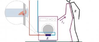
The grounding conductor, according to the PUE, is needed for safety purposes. Under normal conditions, there is no voltage on it, and it works as a conductor only if the insulation of the conducting phase or neutral is damaged. Accordingly, grounding is necessary so that in the event of a breakdown no additional problems arise. For example, when your refrigerator’s protection is broken, and the refrigerator itself is not grounded, touching it will be equivalent to touching the 220 V phase. But if the refrigerator is grounded, it will not give an electric shock, since the potential will go into the ground.
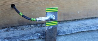
The protective conductor is designated by the letters “PE”. According to the rule, its insulation must be painted in yellow and green stripes. If the diagram has the designation “PEN”, it means that the neutral and protective wires are combined into one. Such a cable should be painted blue with yellow and green stripes at the ends.
To equalize different voltages, all ends of the phase windings are connected into a node, which is called a neutral point, for which a neutral wire is used when connected in a “star”. The star circuit with neutral is used in practice, because in it, at any load, there is no phase imbalance in voltage, i.e. all phase voltages are equal.
If you take into account all of the above, then you probably understand the critical importance of a neutral cable that equalizes voltage in several phases, because its absence threatens with serious problems - from damage and loss of equipment to fires and even the risk of fatal electric shock to a person.
Determination methods
There are 7 ways to distinguish zero from ground. Some methods are simple and involve visual inspection, others require the use of special equipment and are considered more accurate. Knowing how to identify the neutral and ground conductors can help you avoid injuries associated with electric shock.
By labeling
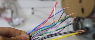
For the convenience of electricians, color marking of wires has been introduced, which allows them to be visually distinguished during installation work.
According to generally accepted rules:
- the yellow-green striped conductor is used for grounding;
- blue and cyan shells are used to mark the neutral wire;
- white, brown, red and other colors are used to indicate phase.
By differential current
This method can be used if you have a residual current device (RCD) or a differential circuit breaker. For research you will need a lamp with wires, which is connected to the phase and one of the conductors.
If the protective device does not work, then the lamp is connected correctly to the phase-zero pair. If the network is de-energized, then the phase-ground wires are involved.
If the residual current device does not work in both cases, the reasons may be:
- equipment breakdown;
- discrepancy between the strength of the current passed through the lamp and the nominal value of the RCD, at which it must de-energize the network.
By grounding contacts on sockets
This test option is used when using a two-pole input circuit breaker and grounding sockets. To conduct the study, the machine is turned off so that there is no connection between zero and ground, and all household appliances are de-energized. In the multimeter, activate the “Dial” mode and connect the device to the ground contact and alternately to two other wires.
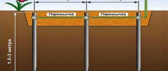
Re-grounding
Re-grounding of the neutral conductor is protection installed at the intervals specified by the rules of the Electrical Installation Code along the entire length of the neutral. The task of re-grounding includes reducing the voltage in the neutral wire and electrical appliances that have been grounded relative to the ground. This property is useful as protection against a break in the neutral wire and in the event of a breakdown of electrical voltage on the housing of electrical devices.
To reconnect, it is necessary to conduct a continuous neutral from the shield to the neutral conductors. In high-rise buildings, various systems are used for re-grounding.
TN
The transformer neutral in electrics is grounded, and the accessible part is connected to it through neutral protective conductors. In normal mode, the electrical receiver is not energized. The TN system is:
- TN-S – the protective and neutral conductors are separated along the length of the entire line;
- TN-CS - the functions of the PE and N wires are combined in one part of the conductor brought out from the transformer.
If communications are connected in a private house, natural grounding conductors are used - metal pins in the ground. Regulatory documents do not recommend the use of natural conductors, since it is impossible to calculate the resistance that the soil provides when current flows.
TN-C
TT Grounding in houses built before the mid-90s, for which a four-wire method was used - 3 phases and 1 neutral. The protective and working functions of the neutral are performed by a common conductor throughout the entire line. The consumers are powered from a PEN cable. It is also used for grounding.
TT
IT Used to supply electricity in suburban and rural environments. The current flows through power lines on poles. Installations are permitted in cases where TN is impossible or very expensive. When an increased current is supplied to the devices, the power circuit is turned off completely through the RCD.
IT
Network with isolated transformer neutral. It is removed from the ground or grounded through a receiver with high resistance. The ground line is carried out along a separate bus, and the socket contacts are already connected to it. The organization of the system is appropriate for educational and medical institutions.
How to determine phase and zero
To determine, use an indicator screwdriver or a test lamp. The devices allow you to identify the necessary wires, because they begin to glow when connected to a phase.
From two wires
When performing the test, the electrical network is not de-energized. The conductive metal rod of the indicator screwdriver is touched to the conductor and at the same time the finger is pressed against the iron plate at the top of the device. If the light indicator lights up, then the sting has touched the phase; when in contact with zero, it remains extinguished.
Classification of power line neutrals
The purpose of power lines is very diverse. There is also a variety of equipment to protect them from leaks and short circuits. In this regard, neutrals are classified into three types:
- solidly grounded;
- isolated;
- effectively grounded.
If the power line with voltage from 0.38 kV to 35 kV is short and the number of connected consumers is large, then a solidly grounded neutral is used. Consumers of a three-phase load receive power thanks to three phases and zero, and consumers of a single-phase load receive power from one of the phases and zero.
With an average length of power lines with voltages from 2 kV to 35 kV and a small number of consumers connected to this line, insulated neutrals are used. They are widely used for connecting transformer substations in populated areas, as well as powerful electrical equipment in industry.
In networks with a voltage of 110 kV and higher, with a large length of power lines, an effectively grounded neutral is used.
Safety precautions during inspection
When working with electrical wires, you must follow the safety rules:
- Check voltage using instruments, and do not rely only on color markings. There are situations when electricians, through inattention or ignorance, installed electrical wiring without observing generally accepted connection conditions based on the colors of the wires.
- Before starting work, visually check the serviceability and integrity of the cable.
- Do not allow wires to come into contact with wet, hot, oily objects or surfaces.
- In factory-made complete switchgears, check the presence or absence of voltage using built-in stationary voltage indicators.
- Testing in electrical installations with a voltage of 35 kW is carried out using an insulating rod by contacting it with live parts. The presence of crackling and sparking indicates the presence of tension.
- Do not touch exposed electrical wiring.
- It is allowed to work with wiring from a stepladder if the height of the cables does not exceed 3 m from the floor. It is prohibited to place ladders on various supports (boxes, barrels, etc.).
Designation of neutral protective conductor
Color of the neutral protective and neutral working conductors
Most often, the marking of the neutral protective conductors is yellow-green. The PUE establishes the basic rules for choosing the cross-section of the current-carrying wire.
The PE has its own grounding loop, or its main tasks can be assigned and combined with the neutral wire, in this case it all depends on the installed grounding system in the building structure. The combination of two conductors is called PEN, its cross-sectional area must be no less than the cross-sectional parameters of the working wire N.
Technical features
In this system, where a common midpoint is used, in addition to the phase-to-phase voltage, there is also a phase-to-phase voltage. The latter is formed between the working zero and the linear wires. The difference between the first and the second is clearly demonstrated below.
Difference between phase and line voltage
The potential difference UF1, UF2 and UF3 is usually called phase, and the values UL1, UL2 and UL3 are called linear or interphase. It is characteristic that UL exceeds UF by approximately 1.72 times.
In an ideally balanced three-phase electric current network, the following relationships must be maintained:
UF1= UF2=UF3;
UL1=UL2=UL3.
In practice, it is impossible to achieve such a result for a number of reasons, for example due to uneven load, leakage currents, poor insulation of phase conductors, etc. When the neutral is grounded, the imbalance of the linear and phase characteristics of the power system is significantly reduced, that is, the working zero allows potentials to be equalized.
What is the phase characterized by?
A phase is a live wire. This conductor is located relative to another, called zero. The rationale for determining the phase is the peculiarity of the substation design. The alternating current generated by them has the same frequency of 50 Hz. At the same time, the emfs are shifted relative to each other in time by a certain phase angle.
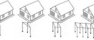
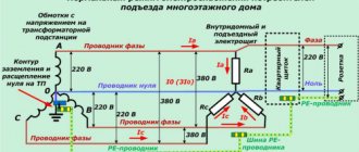
The first figure schematically shows the power supply system of a standard residential property with three phases and one neutral conductor. The second image demonstrates the features of connecting electricity to the apartment from a transformer. The consumer in the form of an electrical appliance is designated as Rн. In this case, two wires come out of the transformer in the form of a phase and a zero, to which the ZML grounding is connected. The third figure shows how clearly the installation of power supply is carried out in the absence of a neutral grounded wire connected to the apartment. Grounding in this situation is located directly in the living space.
The concept of phase follows from the definition of electricity. The nature of the formation and flow of alternating current allows us to understand the nature and purpose of the phase wire. Alternating current differs from direct current in value and direction; it can be observed in sockets and direct connections to electrical panels. Main characteristics of alternating current:
- voltage;
- frequency.
Single-phase current is an alternating current obtained through the rotational movement of a conductor or system of conductors under magnetic flux conditions. The wires can be combined in one coil. In order to transmit electricity, two wires are used, including phase and neutral. The voltage between the conductors is 220 Volts. There are two ways to connect single-phase current to a consumer:
- two-wire;
- three-wire.
In the first case, two conductors are used, one of which carries phase current, and the second is zero. This is an outdated power supply scheme that was used during the Soviet era. The second method involves the presence of one more wire, which is necessary for grounding, which helps prevent electric shock to a person, drain electrical leaks and prevent damage to electrical appliances.
Two-phase current is called the fusion of two phases that are shifted relative to each other. The shift angle can be 90 degrees. For example, you can take two coils with perpendicular axes, which are connected to a two-phase current. As a result, a system of two magnetic fields is formed. The resulting magnetic field will have a vector that rotates at the same angle and at a constant speed, creating a magnetic field.
Why do you need color coding?
The phase and neutral in the operating circuit are determined by an indicator or a multimeter, but these devices are not always nearby. If the electrical circuit is made in accordance with existing standards, then the color of the core insulation can be used to determine their purpose without additional equipment.
This allows you to quickly find the right wire, so the electrician's work efficiency will be much higher.
The letter markings on the conductors are similar to the inscriptions on the terminals and contacts of electrical equipment. It is enough to insert and fix the desired wire into the terminal that corresponds to its marking. To be on the safe side, it is better to additionally check with a tester where the phase is located.