The construction of a modern dacha, as a rule, is accompanied by significant volumes of special electrical work. In addition to the mandatory power supply, as well as the installation of distribution equipment and electrical wiring, great importance is attached to a well-designed and efficient grounding system. Unprepared owners of dacha farms often forget about this important element of personal safety and neglect it. However, according to the requirements of the regulations (PUE, in particular), the operation of ungrounded electrical equipment in personal households is unacceptable, since this can lead to irreparable consequences.
Is grounding necessary at the dacha?
Grounding in a dacha is important because it guarantees reliable protection of all its inhabitants from electric shock. In addition, representatives of electrical networks will not give permission to connect a house to the line if it is not equipped with full grounding or if it does not meet the requirements of the PUE. In suburban buildings, all data on the arrangement of the protective contour are included in the project at the stage of its preparation (along with the development of other communications). In this case, the homeowner has to choose between two options: either invite specialists and pay for their work, or make a grounding device (GD) himself.
Separately about the grounding of some units
In a private home there are some powerful devices that consume large amounts of electricity and pose an increased danger.
It is important to properly ground these units to protect yourself and your loved ones.
Gas and electric boiler
The issue of grounding a gas boiler in a private house should be approached with all responsibility. Otherwise, you may not only lose the automation, which is very sensitive to sudden changes in voltage, but also risk your life, since the gas can explode from any spark.
Don't relax if your gas inspector doesn't require you to install an earth electrode. This is not strictly prescribed by the rules. Take care of your own safety without waiting for unpleasant consequences.
Scheme for a gas boiler
For the boiler, you can use a homemade circuit, which we have already discussed, or purchase a ready-made kit.
Related article:
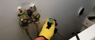
Water heater
The most common mistake in grounding a water heater is connecting it to a phase wire in an outlet. This threatens an emergency phase loss. Only an automatic device can prevent the consequences of such a shutdown, but it is not installed on all units.
It is believed that connecting the grounding contacts to a circuit in the ground leads to premature corrosion of the water heater body, but here the lesser of two evils is chosen. Experts recommend installing a residual current device with the water heater along with the grounding loop.
How to ground a water heater in a private house in the following video:
Watch this video on YouTube
Related article:
Socket
Grounding outlets is a way to protect all other electrical appliances in the house. You should take care of the safety of your home even at the time of laying the wiring. To do this, use a three-core wire, which contains “zero”, “phase” and “ground”. It is very convenient if the wires are braided in different colors; this greatly facilitates installation.
Modern manufacturers produce sockets in which it is difficult to confuse anything. All terminals are clearly marked, so even a beginner can connect the outlet.
How to ground an outlet in a private house in video instructions:
Watch this video on YouTube
Choosing a location for installation
Its efficient and safe operation largely depends on the correct location of the circuit arrangement. There are several recommendations on this matter:
- Do not place the ground loop in a place where people or animals are constantly or frequently present. When the insulation breaks down and voltage is discharged into the ground, a person or animal in the immediate vicinity may be harmed. It is better to take measures to fence such an area.
- Some experts recommend placing the contour on the north side of the building. This is explained by the moister, damp conditions in such an area.
- If the soil is too wet and there is a high probability of corrosion of the metal of the circuit, then it is better to make it from large-section steel. The circuit structure can also be coated with special conductive materials that will protect against corrosion but will not impair electrical contact with the ground.
- You should not place the grounding loop close to heat communications. Over-dried soil has a negative effect on the circuit resistance indicator.
- It is prohibited to place the circuit in close proximity to a gas pipeline running in the ground.
- The depth of the circuit must be below the freezing level of the soil, but not less than 0.5 m.
If you follow these recommendations, you can be sure of the correct location and reliable operation of the ground electrode.
Operating procedure
- The location and grounding design are selected: line or triangle.
- The required number of horizontal and vertical elements is calculated and delivered to the site.
- Tools are prepared: shovel, sledgehammer, welding machine with electrodes, grinder.
- A trench 60–70 cm deep is dug along the grounding profile. Places for vertical elements are marked. It is recommended to dig holes here. The deeper they are, the faster and easier the vertical electrodes will clog.
- The angles and round steel are sharpened and sharpened, and the pipe at the end is flattened.
- After driving, the horizontal electrodes and the busbar are welded to the input panel.
- The welding areas are cleaned of scale and treated with an anti-corrosion compound, such as bitumen. Other parts of the structure cannot be covered with anything in order to maintain a good electrical connection with the soil.
- The trench is filled with homogeneous soil and compacted. Protective grounding is ready.
Basic grounding schemes
Experts recommend using standard and proven grounding schemes for summer cottages. This is justified by the fact that such schemes have been tested for several years and have already proven their reliability and safety.
The most reliable schemes are considered to be:
A recessed metal contour that is placed around the structure. Often the main material for drainage is classic construction reinforcement
The reinforcement rods are connected to each other by a welded metal busbar. Among summer residents, a scheme for placing three electrodes in the ground, which are connected to each other by a steel strip, is also common. The simplest scheme is to place a very long branch at a significant depth, which should be at least 6 meters. Important! Painting the grounding elements that perform the tapping function worsens the conductivity properties. Fundamental ground electrode
This scheme is very thorough, since it is a closed circuit, which is welded in the form of a metal mesh. Experts recommend laying such a mesh on the bottom row of reinforcement in the foundation. Installation of such grounding is possible only during the construction of the foundation.
Preparing the required triangle
The installation location of the electrodes is selected so that it is convenient to connect the grounding bus to the distribution panel. But design dimensions are not mandatory. The sides of the triangle can be less than three meters in length, and the depth of driving the pin can be reduced to 2-2.5 meters. The number of electrodes can also be increased if the soil is dense and it is not possible to drive the pins to the designed depth.
After marking the selected location, you can dig a small pit to a depth of up to 1 meter. At the same time, we dig a trench of the same depth for a grounding bus from the circuit to the base of the house. Sometimes, instead of a pit, trenches are dug along the perimeter of the contour being created, which somewhat simplifies the excavation process
You just need to pay attention that their width allows you to freely carry out welding work and driving in electrodes. It is better to cut the edges of the electrodes with which they will go into the ground at an angle and sharpen them with a grinder
Remember that the metal must be unpainted.
We drive the electrodes into the ground with a sledgehammer in the designated places so that they protrude about 200 mm above the surface level. Then we connect them using electric welding with a common busbar made of steel strip. It is better to refrain from using bolted connections - the threaded contact underground will quickly oxidize, and the circuit resistance will increase critically. Now you can lay a bus from the same steel strip to the foundation of the house.
Expert advice
A slight bend must be provided in front of the mounting point on the plinth to compensate for the linear movements of the tire due to temperature changes. The strip should end with a welded bolt with an M10 thread, to which a copper terminal with a ground wire will be attached to the distribution panel.
Installing a ground loop
The circuit must be placed underground, therefore, to make it easier to enter the ground, the lower end of the vertical grounding conductors is cut at an angle. The ground loop usually has the shape of a triangle, therefore, at a distance of at least 3 meters from the building, a triangular trench is prepared with dimensions: depth 70 cm, width 50 cm. A trench is laid from this triangle to the distribution cabinet. Vertical grounding conductors are driven into the vertices of the prepared triangle to the extent of soil freezing from 1.5 m to 3 m. a segment measuring 20-25 cm should protrude above the soil (inside the trench).
Advice: if the soil is dense, it is possible to prepare holes for mounting electrodes in advance.
When the electrodes are installed, a horizontal ground electrode is welded to the ends of the electrodes that remain above the ground. The joints should be treated with anti-corrosion agents. Next, a grounding wire is welded to this structure using a 10mm bolt. When assembling the entire structure of the grounding loop, twisting is not allowed; all parts are connected only by welding.
After the circuit is completely assembled and installed, it is checked for resistance level. If it does not exceed the norm, then a trench is buried. The wire from the grounding switch goes into the power cabinet and is connected to the grounding line.
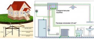
Grounding diagram in a private house
As a rule, power supply in private homes is carried out by overhead lines with a TN-C grounding system. In such a system, the neutral of the power source is grounded, and the phase wire L and a combined neutral protective and working wire PEN are connected to the house.
After the house has installed its own grounding loop, it is necessary to connect it to the electrical installations of the house.
- You can do this in two ways:
- convert the TN-C system to the TN-CS grounding system;
- connect the house to the ground loop using the TT system.
Connecting the house to the ground loop using the TN-CS system
As you know, the TN-C grounding system does not provide a separate protective conductor, so we are converting the TN-C system to TN-CS in the house. This is done by dividing the combined neutral working and protective PEN conductor in the electrical panel into two separate ones, working N and protective PE.
And so, two power wires approach your house, phase L and combined PEN. To get a three-wire electrical wiring in the house with separate phase, neutral and protective wires, it is necessary to correctly divide the TN-C system into TN-CS in the incoming electrical panel of the house.
To do this, install a bus in the shield that is metallic connected to the shield; this will be a PE grounding bus; a PEN conductor will be connected to it from the power source side. Next, from the PE bus there is a jumper to the bus of the zero working conductor N; the bus of the zero working conductor must be isolated from the shield. Well, you connect the phase wire to a separate bus, which is also isolated from the switchboard.
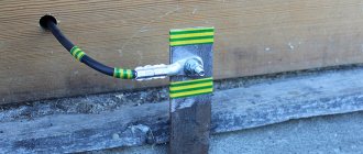
After all this, it is necessary to connect the electrical panel to the grounding circuit of the house. This is done using a stranded copper wire, connect one end of the wire to the electrical panel, attach the other end to the grounding conductor using a bolt at the end, which was specially welded for this purpose.
Connecting the house to the ground loop using the TT system
For such a connection, it is not necessary to make any separations of the PEN conductor. Connect the phase wire to a bus isolated from the switchboard. You connect the combined PEN conductor of the power source to a bus that is isolated from the switchboard and in the future consider the PEN to be simply a neutral wire. Then connect the shield housing to the house ground loop.
As can be seen from the diagram, the grounding loop of the house does not have any electrical connection with the PEN conductor. Connecting the ground in this way has several advantages compared to connecting using the TN-CS system.
If the PEN conductor burns out on the power source side, all consumers will be connected to your ground. And this is fraught with many negative consequences. And so your grounding will not have a connection with the PEN conductor, this guarantees zero potential on the body of your electrical appliances.
It often happens that on the neutral conductor, due to an uneven load across the phases (phase imbalance), a voltage appears that can reach values from 5 to 40 V. And when there is a connection between the network neutral and the protective conductor, it can also occur on the housings of your equipment little potential arises. Of course, if such a situation arises, the RCD should trip, but why rely on the RCD. It would be better and more correct not to tempt fate and not lead to such a situation.
From the considered methods of connecting the grounding loop of a house, we can conclude that the TT system in a private house is safer compared to the TN-CS system. The disadvantage of using a CT grounding system is that it is expensive. That is, when using a TT system, protective devices such as RCDs and voltage relays must be installed.
I would also like to note that it is not necessary to make the outline in the form of a triangle. Everything depends on external conditions. You can place horizontal grounding conductors in any order, around a circle or along one line. The main thing is that their number is sufficient to ensure minimal grounding resistance.
Errors during grounding installation
Very often, the cause of electrical injuries, fires or damage to electrical equipment is non-compliance with the rules when installing grounding.
Here is a list of the most common errors when installing grounding:
- connecting the ground electrode directly to the electrical installation, and not to the ground bus;
- using fence supports, heating or gas supply pipes as a grounding loop, which is strictly prohibited;
- lack of connection between the neutral PEN conductor and the grounding device, installation of switches in it that can disconnect the connection;
- the use of materials that do not meet the requirements of the PUE in terms of thickness and dimensions, which leads to their rapid corrosion;
- welds that are too short;
- lack of anti-corrosion treatment with mastic on welds and strips located on the surface of the ground;
- dimensions of horizontal and vertical elements that do not correspond to the calculation;
- the distance between the pins is too small and not a multiple of their length;
- incorrect application of the CT and TN connection diagram.
DIY grounding device: step-by-step instructions
If you are asking the question: “how to make grounding at the dacha?”, then to complete this process you will need the following tool:
- a welding machine or inverter for welding rolled metal and bringing the circuit to the foundation of the building;
- an angle grinder (grinder) for cutting metal into specified pieces;
- wrenches for bolts with M12 or M14 nuts;
- bayonet and pick-up shovels for digging and burying trenches;
- a sledgehammer for driving electrodes into the ground;
- a hammer drill for breaking up rocks that may be encountered when digging trenches.
In order to correctly and in accordance with regulatory requirements perform a grounding loop in a private house, we will need the following materials:
- Corner 50x50x5 - 9 m (3 segments of 3 meters each).
- Strip steel 40x4 (metal thickness 4 mm and product width 40 mm) - 12 m in the case of one grounding point connected to the foundation of the building. If you want to make a grounding loop along the entire foundation, add the total perimeter of the building to the specified amount and also take a reserve for trimming.
- Bolt M12 (M14) with 2 washers and 2 nuts.
- Copper ground electrode. A grounding conductor of a 3-core cable or a PV-3 wire with a cross-section of 6–10 mm² can be used.
Once all the necessary materials and tools are available, you can proceed directly to the installation work, which is described in detail in the following chapters.
Selecting a location for installing the ground loop
In most cases, it is recommended to install the ground loop at a distance of 1 m from the foundation of the building in a place where it will be hidden from the human eye and which will be difficult to reach for both people and animals.
Such measures are necessary so that if the insulation in the electrical wiring is damaged, the potential will flow to the ground loop and a step voltage may arise, which can lead to electrical injury.
Excavation work
After a location has been chosen, markings have been made (for a triangle with sides of 3 m), and the location for the strip with bolts to be laid out on the foundation of the building has been determined, you can begin excavation work.
To do this, it is necessary to remove a 30–50 cm layer of earth around the perimeter of a marked triangle with sides of 3 m using a bayonet shovel. This is necessary in order to later weld the strip metal to the ground electrodes without any special difficulties.
It is also worth additionally digging a trench of the same depth to bring the strip to the building and bring it to the facade.
Hammering of grounding conductors
After preparing the trench, you can begin installing the ground loop electrodes. To do this, you must first sharpen the edges of a 50x50x5 corner or round steel with a diameter of 16 (18) mm² using a grinder.
Next, place them at the vertices of the resulting triangle and, using a sledgehammer, hammer them into the ground to a depth of 3 m
It is also important that the upper parts of the grounding conductors (electrodes) are at the level of the dug trench so that a strip can be welded to them
Welding work
After the electrodes are driven to the required depth using a 40x4 mm steel strip, it is necessary to weld the grounding conductors together and bring this strip to the foundation of the building where the grounding conductor of the house, cottage or cottage will be connected.
Where the strip will reach the foundation at a height of 0.3–1 moth of earth, it is necessary to weld an M12 (M14) bolt to which the grounding of the house will be connected in the future.
backfilling
After all welding work has been completed, the resulting trench can be backfilled. However, before this, it is recommended to fill the trench with saline solution in the proportion of 2-3 packs of salt per bucket of water.
Afterwards, the resulting soil must be compacted well.
Checking the ground loop
After completing all the installation work, the question arises: “how to check the grounding in a private house?” Of course, a regular multimeter will not be suitable for these purposes, since it has a very large error.
To perform this activity, the F4103-M1 devices, Fluke 1630, 1620 ER clamps, and so on are suitable.
However, these devices are very expensive, and if you do the grounding at your dacha with your own hands, then to check the circuit, an ordinary 150-200 W light bulb will be enough for you. For this test, you need to connect one terminal of the lamp socket to the phase wire (usually brown) and the second to the ground loop.
If the light bulb shines brightly, everything is fine and the grounding circuit is fully functioning, but if the light bulb shines dimly or does not emit a luminous flux at all, then the circuit is mounted incorrectly and you need to either check the welded joints or install additional electrodes (which happens when the electrical conductivity of the soil is low).
Simple calculation using an online calculator with an example
There are special programs for calculating grounding - MatchCad and Excel, but you need to be able to work with them. The easiest ones for users are online calculators. The climatic region, the type of soil of the upper and lower layers, the length and diameter of the electrode are entered into the appropriate fields.
At the output, you will receive all the data at once - the resistivity of the soil in your area, the resistance to current spreading of the vertical ground electrode and the connecting strip, the total resistance, the number of pins and the length of the strip. By changing the data, you can determine the most compact configuration based on the characteristics of the materials you have.
Example. For a private house connected to a network with an alternating current voltage of 380 V, the normalized resistance is 30 Ohms. The climate zone is selected from the temperature regime in January and July - II. The top and bottom layers of soil are clay. For grounding, vertical electrodes 2 m long and 25 mm in diameter are used. For the horizontal element we will use a strip 10 cm wide. The standard laying depth is 0.7 m.
With these data, the calculator calculated that 3 rods will be required for a horizontal grounding rod length of 4 m, which suits us quite well. 2 electrodes will be at the edges of the strip, one in the center.
How to do grounding correctly in the house
As a rule, a TT system is used to supply electricity to a private house; in such a system, the PE grounding wire is connected to the grounding loop, and nowhere else. With such a system, it is necessary to make a high-quality grounding circuit so that in the event of a short circuit to ground, the short circuit current is sufficient to trip the circuit breaker. Let's look at how to do grounding correctly in a private home.
The circuit consists of grounding conductors and metal strapping. Grounding electrodes are made of metal pins 2-3 meters long; they go completely into the ground. These pins and the distribution board in the house are connected by metal strapping. Metal pipes, angles, and rods can be used to make pins. Reinforcement cannot be used, as it rusts faster and loses its grounding properties. It is convenient to connect the pins together with a metal strip. There are fundamentally two ground loop schemes:
- Linear diagram of the grounding circuit, grounding electrodes are laid in a row and connected in series.
- Closed loop circuit, such as triangular and square, in which all the ground pins form a closed circle. This scheme is more reliable and optimal. If the area near the house allows, then use it. The most optimal scheme would be a triangle; the distance between the pins should be the same from 1 m to 1.5 m.
The organization of grounding in a private house can be divided into three stages of work: installing a grounding circuit in the ground, connecting the circuit to the electrical panel and checking the operation of the grounding.
STAGE1
- We mark the area under the contour of the triangle, and dig a trench 70 cm deep in the direction of the building.
- At the corners of the triangle, metal corners or pipes are driven into the ground to a depth below the freezing level, about 2.3 meters. The ends of the pins are driven in so that after filling with soil there is still about 50 cm of soil above them.
- Then these ends are connected by welding with metal strips, thereby forming a closed loop in the form of an isosceles triangle.
- Then a metal strip leading to the house is welded to the contour. At its end, on the wall of the house, we weld a bolt to which the grounding wire from the busbar in the electrical panel will be attached.
- Welding seams are painted with bitumen paint or mastic to protect against corrosion.
- We fill the trench with soil and paint the earth tire that protrudes from the ground to protect it from corrosion.
STAGE2
To connect the earth bus to the panel, it is better to use a yellow copper wire with a cross-section of at least 10 sq. mm.
The copper wire is also attached to the panel with a screw connection to the housing. If the switchboard door is not grounded, ground it with another wire.
Advice! Select in advance the grounding bars in the panel with the required number of holes for different lines, since it is prohibited to attach two wires to one point.
STAGE3
Check the functionality of the completed protective. It is better to carry out such a check once every 3 years, for your safety. The check is carried out with an ohmmeter. It may seem that you can check your circuit by connecting an ordinary light bulb to the phase and circuit and it will light, but this is erroneous due to low power consumption.
The resistance of the ground loop should not be more than 4 ohms. I advise you to invite an electrician and be sure that your ground loop is working correctly.
Effect of shielding
To calculate the distance of the pins relative to each other, a shielding coefficient is used, which takes into account mutual influence. When they are located close together, one spreading stress is superimposed on another, and the effect is enhanced.
To reduce the effect, you can increase the length of the pin. Typically, this design is made of 2 rods - first 1 is driven in, then the other. But in private housing construction such grounding electrodes are not used due to the complexity of installation.
By connecting vertical pins with a horizontal element, we reduce the spreading area of each of them. In calculations, its influence is taken into account by a coefficient depending on the number of electrodes in the circuit.
What is a ground loop: definition and device
A grounding loop is a special design made of electrically conductive materials with low electrical resistance, providing instant drainage of electric current to the ground. It consists of 2 interconnected parts - an internal and external system. Their reliable connection is carried out in the input electrical panel.
The design of the external subsystem must ensure the transition of the electrical signal to the ground with its distribution over the area. It is based on several electrodes buried in the ground and connected to each other in a circuit using plates. A bus of sufficient cross-section extends from the plates, which is inserted into the electrical panel, where it is connected to the internal subsystem. Each electrode is a metal pin buried (driven in) to a certain depth.
The internal subsystem is the distribution of the grounding circuit throughout the house. Conductors from the switchboard are routed to sockets, to the housings of powerful electrical devices, and to metal mains (pipes). The individual conductors are combined into a common bus, which is connected to the external circuit bus.
The principle of operation of the ground loop is quite simple. The electric charge accumulated in metal elements (installation housings, pipelines, fittings, etc.) when the insulation of the electrical network conductors is damaged or induced from external sources, rushes through the wires of the internal subsystem, which have low electrical resistance, to the circuit of the external subsystem. It “flows” into the ground through electrodes buried in the ground. In turn, the earth has a huge capacity, which allows it to freely “absorb” such electricity leaks.
What does it give
Protective grounding is necessary to ensure electrical safety in the home. If done correctly, when a leakage current appears, it leads to immediate tripping of the RCD (damage to electrical insulation or when live parts are touched). This is the main and main task of this system.
The second function of grounding is to ensure the normal operation of electrical equipment. For some electrical appliances, having a protective wire in the socket (if any) is not enough. A direct connection to the ground bus is required. For this purpose there are usually special clamps on the case. If we talk about household appliances, these are a microwave oven, an oven and a washing machine.
The main task of grounding is to ensure the electrical safety of a private home.
Few people know, but a microwave without a direct connection to the “ground” can emit significant radiation during operation; the reception level of radiation can be life-threatening. In some models, you can see a special terminal on the back wall, although the instructions usually contain only one phrase: “grounding is required” without specifying exactly how it should be done.
When you touch the body of the washing machine with wet hands, you often feel a tingling sensation. It is not dangerous, but unpleasant. You can get rid of it by connecting the ground directly to the case. In the case of an oven, the situation is similar. Even if it does not “pinch”, a direct connection is safer, since the wiring inside the installation operates under very harsh conditions.
With computers the situation is even more interesting. By directly connecting the ground wire to the case, you can significantly increase the speed of the Internet and minimize the number of freezes. It’s that simple because of the direct connection to the ground bus.
Do you need grounding in a country house or in a wooden house?
In holiday villages, grounding is mandatory. Especially if the house is built of flammable material - wood or frame. It's about thunderstorms. At dachas there are a lot of elements that attract lightning. These are wells, boreholes, pipelines lying on the surface or buried to a minimum depth. All of these objects attract lightning.
At dachas there is a high probability of being struck by lightning
If there is no lightning rod and grounding, a lightning strike is almost equivalent to a fire. There is no fire station nearby, so the fire will spread very quickly. Therefore, in combination with grounding, also make a lightning rod - at least a couple of meter-long rods attached to the ridge and connected to the ground using steel wire.
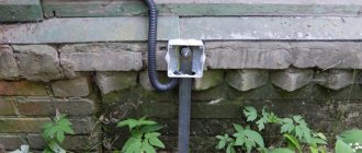
Grounding device on the street near the house
The installation of a grounding loop in a private house consists of pins driven vertically into the ground, which are tied together with conductors. And this whole structure is connected to the distribution panel in the house. Before making grounding in a private house, you need to prepare the necessary tools and materials.
The tools you will need are shovels, a crowbar, a sledgehammer, a hammer, a welding machine with electrodes, a grinder, and wrenches. From materials:
- metal corner measuring 50x50x5 mm;
- steel strip 40 mm wide and 4 mm thick;
- metal wire rod with a diameter of 8-10 mm.
In purely structural terms, the house grounding loop is an equilateral triangle, into the corners of which metal grounding conductors are driven. This is what a metal corner is used for. The driving depth is 2.5-3.0 m. You can do this yourself with an ordinary sledgehammer. If the soil in the area is hard, then you can first make a deepening with a drill to a depth of 1.5 m, and then finish off the corners with a sledgehammer.
The installation process must begin by marking the size and shape of the ground loop on the ground. After that, a trench up to 60 cm wide is dug around the entire perimeter to make it convenient to carry out welding, and 80-100 cm deep. Grounding conductors are driven in. To ensure that the process of inserting the corners into the ground goes smoothly, it is recommended to sharpen their ends into a cone. There is no need to hammer it in all the way; you want the edges of the pins to remain sticking out above the bottom of the trenches, approximately 20-30 cm.
Now it is necessary to connect the corners with each other using horizontal elements of the ground loop. A metal tape is used for this. The connection is made only by electric welding. There are no bolts that will become corroded underground, which means partial or complete lack of contact, which will lead to ineffective grounding in a country house.
The next stage is connecting the completed circuit to the distribution panel in the house. For this you can use either wire rod or the same metal strip. In the yard, the connecting circuit is drawn in a trench, inside the house along a wall or baseboard. At the end of the conductor that entered the house, an M6 or M8 bolt is welded. A ring of wire responsible for the internal grounding of a private house will be put on it. Fastening is done with a similar nut. Joint insulation may be necessary.
Welding areas must be treated with anti-corrosion compounds. But it is prohibited to paint the entire contour or coat it with any protective compounds. Because the system requires full contact with the ground, where stray currents will go.
At this point, the installation of the grounding loop for a private house can be considered complete. Therefore, make sure that the welding joints are strong, after which you need to dig the trenches with shovels. By the way, this technology can also be used to construct a lightning rod (lightning rod) system. You can make such a grounding device in a private house with your own hands.
It should be noted that the correct form of grounding for a private house is not necessarily a triangle. You can use square, circle, line and other shapes
It is important that the circuit itself does not create resistance, so the maximum number of ground electrodes driven deep into the earth and their horizontal counterparts is as large as possible. Although the triangle is a time-tested option
And one more important point - the distance from the home grounding system circuit to the foundation of the house should not be less than one meter.
Soil resistivity
In a system of several elements, the number, distance, depth and even the shape of the rods themselves are mutually dependent. The resistivity of the soil has a great influence. The ability to conduct electric current varies among different types of soil. It is lowest in stone due to its low water content.
The best conductor is water; accordingly, the wetter the soil, the better the conductivity. For example, the resistivity of loam is 100 Ohm/m, and that of sand is 7 times greater - 700 Ohm/m.
To accurately find the soil resistivity, you need to dig a hole 0.7-1 m deep and determine the type of composing rock. You can measure conductivity with a special device.
The calculation uses a climate coefficient that takes into account soil moisture depending on the region.
Touch tension and step tension should be kept to a minimum. The PUE contains norms under which a person’s life is not in danger.
The need for grounding in a summer cottage
Of course, first of all, we are interested in the health and life of our family and guests. We are all designed in such a way that when an unacceptable current flows through the human body, death occurs. High voltage itself, even with low current, causes burns. So touching an old refrigerator, in which the phase has got on the body, will not make anyone happy.
Adventures can happen in the shower at your dacha, and worse: the heating element of a homemade water heater can be broken, and when you try to turn on the water, an electric shock is inevitable. A repeatedly overheated electric drill, welding machine or hammer drill is also dangerous: voltage may appear on the metal body of the tool.
It is noteworthy that in a drunken state, the resistance of the human body becomes noticeably lower than 1 kOhm, and the damage will be even stronger. Of course, where else to relax if not at the dacha? This means there is another reason to install reliable grounding! The use of devices for protecting people, electrical wiring, equipment and devices such as RCDs is also fully possible only if there is grounding.
Grounding schemes for a private house
There are several grounding schemes in an individual cottage: TN-C, TN-CS and TN-S. The first letter in the abbreviation indicates the method of connecting the “ground” to the power source, the second deciphers the characteristics of the consumer.
TN-C circuit
This convenient variety is distinguished by the fact that the conductor simultaneously performs the functions of protection and a working device. This option is often used in old houses due to its ease of implementation and cost-effectiveness. However, due to the lack of a separate protection circuit during an accident, there is a possibility of a short circuit. In modern cottages this option is not used because it does not meet regulatory requirements.
TN-S circuit
In this circuit, separated conductors are used. In an emergency, no voltage is released to the body of the household appliance. This option is considered the safest because it protects against electric shock. However, to implement such a scheme you need to put in a lot of effort and spend additional money.
TN-CS circuit
This is a combined version in which two conductors coming from the power source are combined into one. In this case, an additional PE type protective conductor is installed at the entrance to the house. This scheme is recommended to be used as the main model in buildings for any purpose, including private houses. Its advantages are reliability and ease of assembly. Thanks to the use of an additional conductor, the likelihood of a fire during a short circuit is minimal.
conclusions
Do-it-yourself 220 V grounding in a private house will allow you to protect yourself and your family members from electric shock. In addition, grounding a private house is necessary for concluding contracts with an electrical supply organization or when putting an object into operation during new construction, reconstruction or major repairs.
To perform grounding with your own hands, it will be enough to read this information article and have some skills in electrical engineering.