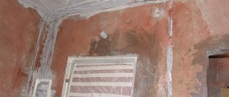
The supply of electricity to the house is handled by the relevant organization. This type of work is associated with certain risks (all operations are carried out without removing the voltage), so electrical safety rules must be strictly observed. The choice of cable for introducing electricity into a private house (section, number of cores, material) lies entirely on the shoulders of the owner of the site. The durability of the electrical network in the house directly depends on this choice, so you should approach the work very seriously.
Cable entry can be carried out by air - from the pole to the house. But they also resort to introducing the cable into the house through the foundation, underground.
Subscriber branch: concept, principle of operation
On each street there are main power lines, the voltage through which comes from the nearest transformer substation. A higher potential difference of 6 or 10 kV arrives at the transformer. But this information is solely for general development, since the main line voltage is 380 V, and between the phase and the neutral wire - 220 V.
To lay a cable from a pole to a separate consumer - a private house, it is necessary to install a subscriber branch from the main line. A subscriber branch is the supply of electricity to an individual consumer. With this procedure, you must correctly calculate the wire through which the electricity will be supplied.
Pole connection
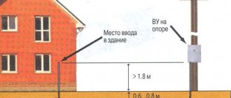
Next, we will consider ways to route the cable from the pole to the home electrical network. The least financially expensive option is to supply electricity by air. According to the requirements of technical regulations, the height at which the cable is inserted into the building should not be lower than 2 meters 75 centimeters.
If this standard is feasible, an RCD (residual current device) is mounted on the wall. A cable is supplied to the RCD from the pole.
If the above height cannot be achieved, a stand made of a metal pipe is installed. The stand can be straight or in the form of a “gander” (curved). Each of the outlets has its own methods of fixation on the wall.
The distance from the pole to the entry point cannot be less than 10 meters. However, if this distance exceeds 11 meters, additional support will be required. In this case, the distance from the support to the power line should be no more than 15 meters.
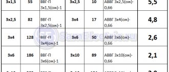
For lines up to 10 meters long, copper wire with a 4 mm cross-section is used. If the distance is between 10 and 15 meters, a 6 mm section will be needed. For aluminum SIP wires, the diameter must be at least 16 millimeters.
Advice! If you use a regular SIP rather than a fire-resistant one, it is recommended to choose a copper cable of the VVGng brand.
Prices for copper wires are much higher compared to aluminum wires. Usually, in order to save money, aluminum wires are connected from the pole to the house.
The eyeliner procedure can be carried out in two ways. The first option involves tensioning a cable or support wire, to which a conductive cable is then attached. The cable is fixed using clamps.
Advice! If you plan to lay the SIP along the wall, you will need clamps (SA50, SFW50), since the minimum permitted distance from the cable to the wall is 6 centimeters.
In the second case, additional supports and fastenings are not used. Protective functions are assigned to insulators made of porcelain, glass or polymers, and to special fittings.
Thanks to the safety margin, the fittings provide reliable cable protection in case of accidents. Under powerful mechanical influences, the reinforcement may be destroyed, but the cable will retain its integrity and continue to perform its function - transporting electricity.
From the building entrance area to the electrical panel, the cable is placed in a metal pipe for safety reasons.
Advice! Before entering the house, it is recommended to bend the cable downwards - this will prevent water from penetrating through the protective pipe. Moreover, it is advisable to do this regardless of the presence of a sealant, since it will still dry out over time and lose its functionality. This simple measure will reduce the risk of a short circuit in the future.
The main disadvantage of the air liner method is its open location, which is associated with the risk of damage. Overhanging wires create difficulties for the access of large vehicles.
Whoever carries out the electrical installation work to insert the SIP cable into the building, the process must be agreed upon with the energy supply organization.
Each location may have different technical requirements (location of installation of the meter, a solid section of self-supporting insulated wire or the possibility of connecting via cable, etc.).
If the wiring is done technically correctly, the input cable will be safe and will last for many years.
A modern dacha is a full-fledged home in which the owners create comfort and equip it with various household appliances. And work on the land plot is mechanized as much as possible, purchasing electric lawn mowers, pumps for watering, cultivators and much other equipment. Most of these mechanisms and numerous devices operate using electrical power. Therefore, energy supply becomes the most important component of the entire engineering of a house and requires competent wiring directly in the residential building, connection to an overhead power line from a pole and, if necessary, installation of an additional support.
How cable tension is done
After fixing the conductor on special rollers, begin to tension it. This requires the following tool:
- hand winch;
- stretching device;
- dynamometer.
The hand winch is attached to the nearest support using anchor bolts, and the cable is pulled along it using a tensioning device. The tension force is regulated by technical documentation and is controlled using a dynamometer.
Taking into account the features of a specific house in the diagram
Among other things, the connection diagram must take into account the characteristics of the materials from which the house is built. Under no circumstances should a plan diagram for a brick house be used in a wooden frame house without any modifications. These materials have different fire resistance and different electrical conductivity. It is necessary to take into account what material is located close to electrical components - metal, wood, plastic or wet tiles - and provide sufficient insulation and maintain the required distance from live parts. All this must be included in the electrical connection diagram.
Subscriber branch cable cross-section
The regulated procedure for laying conductors through the air is specified in the rules for electrical installations. The requirements of the rules are established for power lines with voltages up to 1000 V.
Calculations of the cable cross-section should be based on the operating mode: normal, emergency or installation. Since the branch is standard, you should select the normal (nominal) mode. The PUE provides for the minimum permissible wire cross-section:
- It is allowed to use a wire made of a standard aluminum alloy (not heat-treated) with a cross-section of at least 25 mm².
- When using a conductor made from a combination of steel and aluminum (heat-treated), its cross-section should also be 25 mm².
- If a copper wire is laid, its cross-section can be 16 mm².
The above indicators are suitable for standard ice wall thicknesses of no more than 10 mm. If the thickness reaches 15 mm and above, then the cross-section of the aluminum and steel-aluminum cable remains unchanged, and the copper conductor must be increased to 25 mm².
Information is presented in Chapter 2.4 of the PUE.
Fittings for fastening SIP wires
SIP fittings ensure the correct and high-quality process of transmitting electricity through the air. The structures must be made of moisture-resistant materials and be suitable for single-phase or three-phase network voltage. Replacement of products is allowed once every 20 years.
List of required materials
Anchor brackets
In electrical engineering practice, the following types of fittings are used:
- Anchor brackets – 1 per house and power line support. Aluminum devices are not subject to corrosion or temperature fluctuations. Fixed with stainless steel bands.
- branch terminals – 4 (220 V) or 8 (380 V) pieces. They create contact when connecting cables with a cross-section of 6-150 mm2 with conductors with a cross-section of 1.5-6 mm2.
- Anchor clamps – 2 pcs. The elements provide fixation of insulated wires on branches up to 1000 V. Internal wedges made of thermoplastic prevent damage to the insulating layer;
- intermediate clamps. With their help, you can connect SIP-4 to an intermediate or corner support. The material has a UV-resistant housing.
- Hooks. They are used to guide a conductor through the air on a wooden, metal support or wall surface.
You will also need a sleeve, a corrugated metal sleeve for supplying cables through the wall of the building.
The main operating parameters used to calculate the cable
To connect the cable to the house, you need to decide on its cross-section. The cable cross-section is its area at the cut site. Generally accepted standards (according to the PUE) are indicated in the previous section. The main operating parameters by which the cable cross-section is selected are its cross-section and rated current.
But in addition to the cross-section, a certain conductor material is also needed. Nowadays, copper wires are most often used; they have lower resistance, but are more expensive. Aluminum does not have such high conductivity, but its price is lower than that of copper products. It should be remembered that with the same load, the cross-section of the aluminum conductor should be larger than that of copper.
And the last parameter is the number of cores, but with this everything is much simpler. When introducing only one phase and a working zero into the house, a two-core cable is used; when introducing three phases and a zero, a four-core cable is used. In both options, the cross-section of the zero conductor may be smaller than that of the phase conductor.
CS-CS.Net: Laboratory of the Electroshaman
The house of a Belaal user at the time of a fire due to a fire in the meter.
Today we will have a SCARY post. Because it's time to start NIGHTMARES not with abstract things, but with real stories! I will make another Nightmare based on photographs of a guy who is engaged in servicing floor panels outside the Urals. There is actually a cool lottery in use: “Choose where you like to unscrew the zero for the entire floor.”
Almost all the photos in this post are NOT MY own. They belong to my readers. They sent them to me by email or left links in the comments to various posts. I needed to crop the photos, so I signed them with a general copyright. In the text of the post I will indicate where I took the photos from. If I messed something up or forgot something, you can write to me or in the comments, and I will sign the authors in the text of the post.
I was inspired to write this post by several firefighter channels that I somehow dug up on YouTube. Off the top of my head I remember “I am a Fireman” and “Daring Fireman”. I advise you to stick to them for a couple of hours to understand what a fire is and how difficult it is to put it out. And the worst thing is when the network input into the house is made in such a way that it cannot be turned off . And some villages in the regions suffer from this: the input from the pole immediately enters the house and goes to the meter or input machine, but inside the house. We'll talk about this today.
But THE nightmare that several people have already encountered is the SIP wire and its peculiarity that it burns like a candle. The title photo of the post was provided by user Belaal from the community, who took a photo of his own house burning at dawn. Having managed to run out with my family. The cause of the fire was the SIP installed inside the house by would-be electricians and poor contact in the meter inside the same house. Fucked up.
Combustible SIP wire. Why CAN’T he be brought inside a residential building?
Why-why? Yes, because it is flammable . This is not a mistake or some kind of omission, but the SIP is simply designed that way. The fact is that chemically it is possible to obtain two types of materials for external insulation: either one that is resistant to sunlight, but burns, or one that does not burn, but is not resistant to sunlight.
Therefore, sooner or later Niled (as I understand it) took and designed a special wire for air ducts. In principle, I have samples lying around, so I can make a small post with photos of SIPs and clamps. I think I will, yes. SIP is a WIRE, not a cable. It is created specifically for air ducts and has a huge number of different fittings so that it can be easily mounted and connected to it.
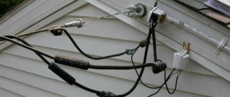
SIP is self-supporting - it does not need any supporting cables or additional insulation. Therefore, by the way, the way the electrical networks lower it into the pipe when installing shields on the pole is a gross mistake for the SIP. You can’t do this with SIP (photo from a post about ASU and hatred):
Idiot connection of SIP to ASU in corrugation
Special clamps have been created for SIPs that cover a wide range of sections and types of wires: insulated (with sharp teeth for piercing) and non-insulated (with flat contact plates). Everything is thought out and made so that the SIP is located only on the street, and if we want to connect an underground cable to it, then we use special clamps.
Again. VIP - COMBUSTIBLE! When burning, it will drip burning molten drops and set everything around on fire! Because of this, it is FORBIDDEN TO BRING IT INTO THE HOUSE! He should only walk ON THE STREET!
But here, as usual, they don’t care about the rules! Moreover, in two options: they didn’t steal (but they burned to hell) or in the option “fuck these stupid rules, now I’ll put him in a chimney.” Here is a photo from a post about the bulkhead of a panel on one customer’s dacha hacienda:
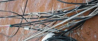
The SIP from the pole goes into the HDPE pipe and pretends to be a VbBShV cable
It’s not visible here (the photo was taken almost by accident, I didn’t know that I would post it), but the SIP, lovingly wound into a bundle with electrical tape, goes into a HDPE pipe, which is tied with wire to a corner driven into the ground. And, of course, it appears in a wooden house inside a shield with a counter like this:
There was an old, useless metering panel left in the house.
What happens if the SIP suddenly lights up? Everything around will be filled with burning drops and the house will burn, as it was in the title photo of this post by Belaal .
Fine! The second part of my thoughts: why should the SIP light up? But because it is made of aluminum, and aluminum flows under the pressure of a tightened screw and needs to be tightened. Sometimes (rarely, but accurately) situations arise when a bad contact heats up and then sets fire to the insulation of the SIP.
That's how it happens. Please note that the input machine to the very sad counter is still turned on here.
Metering board with a burnt-out meter (poor SIP contact)
And this is how it was at the General Drozd facility. Here is a photo from his LiveJournal post. Here the back of the counter got fried:
Burnt-out meter (poor SIP contact), General Drozd
Did you see how it blazed? In this case, the metering board was on a pole. And if this had happened in the house, there would have been a fire.
Therefore, beat with a stick those who are trying to drag the SIP into the house. There's no place for him there! We’ll talk about what to do a little later.
Shitty connections. Shield on the facade from Funt. It's better to burn, but don't steal!
Go ahead! Now I have a few greetings from Kirich Funt. He went to visit his relatives in the region and saw this input panel there in the outback:
Input panel on the facade of a wooden house with a burnt terminal block (Funt)
First, check out some frail SPD. I have a feeling that this is an SPD for low-current networks. And then they put him in the security forces. Most likely, under real overvoltages it will bang. Maybe the machine gun will blow up. Hehehe.
Input panel on the facade of a wooden house with a burnt terminal block (Funt)
But the most fun and trashy thing is THIS:
Input panel on the facade of a wooden house with a burnt terminal block (Funt)
If anyone doesn’t understand, these are aluminum conductors of a special wire for air ducts (AVC), which should protect the line from false connections and theft. The phase conductor is located in the center, and the zero conductor entwines it. It's similar to coaxial cable.
Well, they made such a fucking wire. How to connect it inside the shield? After all, here we have a TT system, in which anything can arrive at zero. This means that the zero must be isolated (how and with what if it intertwines the phase?). And then somehow stuff these aluminum strands into the terminals of the machine or somewhere else.
This is where resourceful power engineers decided to install a regular plastic terminal block, which I wrote about a long time ago. Totally fucked up. This wire itself forces us to make fire-hazardous shields. Do you remember the value of the input machine? It's on 16A! That is, this is how it got burned at a current of ONLY 16A!
And that's not all. Do you know where this plastic shield is located? HERE'S WHERE:
Input panel on the facade of a wooden house with a burnt terminal block (Funt)
On the facade of a wooden house. And to ensure that the house burns down, the input wire runs under the façade cladding. Oh, and Kirich and I did a lot of fuss and brainwashing there! Kirich - live, and I'm virtual!
Methods for switching from SIP to copper on the facade.
Where have we come to this point? We realized that SIP supports and joyfully spreads the fire. Therefore, his place is only on the street, and under no circumstances should he be brought into the house. We also saw how this combustion occurs and what the crappy aluminum contacts are fraught with.
Let's think about how we can arrange entry into the house so that there are no problems with it. Obviously, the most convenient way is an underground armored cable: bury it from a pole or metering panel on a pole - and run it into the house.
What about SIP? Bring it only to the facade of the house and there switch to a copper cable, which is already brought into the house. I’ll emphasize this idea once again: SIP was created ONLY for overhead lines - lines that run through the air openly outdoors. If you need to drag an overhead cable into a shed, then you are dragging copper from the house. On the front of the house, switch from copper to SIP and extend it to the barn. At the barn, switch to the copper again and take it into the barn. That's it and that's it!
A long time ago on MasterCity there was this photo of the ideal, as it was written there, option for switching to copper on the facade of a house:
An example of a transition from SIP to copper cable through special clamps
Yes, it can be used as a sample, because everything here is done correctly: the SIP is held on an anchor clamp by a ring screwed into the wall of the house. It is located at a distance from the facade and does not touch it. The copper cable is routed out of the house through a steel pipe, the outlet of which is bent downward to prevent water from pouring into it. Copper and SIP are connected to each other through special clamps, and insulating caps are put on the SIP cores.
Additionally, the author of this photo wrapped the copper wires with black electrical tape to make them light-resistant. This photo is quite old, and it is not known what kind of electrical tape it was. Either some kind of specially light-resistant one (possibly from 3M), or regular one. If it’s ordinary, it will quickly fall apart.
And here is a version of how one of the comrades with whom I corresponded via soap made the transition to copper. The idea is good, but I completely disagree with it: the SIP goes along the facade of the house in a plastic pipe and, although this pipe has a certificate of non-flammability, this is still not the right solution: it is not light-resistant and will sooner or later collapse. If there was steel here, it would be great!
One example of the transition from SIP to copper via terminals on a DIN rail
But sometimes a more complex problem arises when it is necessary to immediately solve the issue of introducing a self-supporting insulated insulation system, and surge protectors, and connecting the ground loop, and sometimes placing the meter in or near the house. And that’s where I came up with a comprehensive solution.
Grounding board and surge protector on the facade of the house. We solve all problems with one shield.
In general, this option is quite established in my mind and now I talk about it at all consultations on shields. And I myself liked this idea in the style of “Damn! How come I forgot about you?” To understand what I’m getting at, let’s write down the problems that we need to solve when introducing electricity into the house:
- Grounding and lightning protection circuit . It is the contour , and not the notorious triangle that everyone loves so much. If you are doing lightning protection, then you need to drive grounding conductors into at least two, or better yet, four corners of the house and tie it all into a single strip. If you don’t, then it’s enough to plug in one ground electrode with control of the circuit resistance.
- PE input from the ground loop into the shield . Most often, the ground loop itself is made of a steel strip or wire. It is clear that dragging her into the shield is stupid. How can I get it into a white and beautiful AT/U series shield, for example? You can also tell me to weld it to the shield body, heh. Therefore, somewhere on the street/basement, a bolt is welded to the strip, to which an ordinary PuV/PuGV copper wire with a cross-section of 10 square meters is screwed through a TML tip, which is then brought into the house. Such a connection must be somehow protected from earth, moisture and made serviceable.
- External disconnector in case of fire or emergency . It would be nice if there was a disconnect switch somewhere outside the house that could be used to turn off the house.
- SPDs . They need two things (in the toughest version): a metal shield, where they can safely and harmlessly bang or catch fire, and PE as close as possible to the ground loop. And between the SPDs and the shield that we protect with them (our shield at home), it is also advisable to make some distance (several meters of cable).
- Transition from SIP to copper . We have already talked about this: SIP cannot be brought into the house.
What are we doing? At first it seems that I wrote out a list of points that contradict each other. How the hell do you switch from SIP to copper and immediately install SPDs and also connect a strip from the circuit?
So here’s a good and competent (in my opinion) solution: a metal input panel on the facade of the house! This is not a shield for the meter (but it can be combined with it), but a special shield where SPDs can be installed, SIPs in a metal pipe and a steel strip from the ground loop can be installed.
It is most convenient to make such a shield based on the ST series from DKC. Here is the shield that I made for a set of shields in Pushkino:
Shield for main protection and surge protection devices on the facade of the house
Here we have the main ground bus (GZB), to which PE will come from the ground loop and a number of “Input-Output” terminals (terminals of 16 squares, connected in pairs by jumpers), which are needed to connect the input cable from the ground. , input cable to the house and make a branch for installation of SPDs inside this panel. The shield itself will be located on the wall of the house.
And here is another example of such panels (metering for a pole and surge protection for the facade) for a house in Gribanovo:
The metering panel consists of an input machine, a meter and a voltmeter
The beauty of this idea is that we are not trying to cram brutal and voluminous things into our beautiful DIN-rack system (as was the case, for example, in the panel in Tomilino), but are bringing everything voluminous to the facade of the house. And a three- or five-core cable will already arrive in the shield (cabinet) of the house, and in that shield it will be possible to operate in exactly the same way as in an apartment – just take the power and use it, without thinking about any grounding systems.
A small metering panel and an SPD panel for this panel (Gribanovo)
In the end, we can say this: if you know that you will never need any SPDs, lightning protection and other amenities, then switch from SIP to copper on the facade of the house and install it in the house right away. If you want to make a reserve for the future, then organize yourself such a shield on the wall (facade) of the house and drag the input from the ground loop and the input from the pole there. And in the future it will be possible to turn around in this shield.
It so happened that Kirich Funt was redoing another input from his relatives, but in a different house. And that’s where we made such a shield on the facade with a reserve for the future.
DKC ST series panel on the facade of a house for switching from SIP to copper, grounding, SPD and metering (Funt)
The air input is transferred using compresses to two cables VVG-ng-LS 1×10, which are then lowered in a pipe to the shield on the wall.
Transition from input to VVG cables (Funt)
The shield looks like this for now. If in the future you need to add SPDs or something else here, then there is a place.
DKC ST series panel on the facade of a house for switching from SIP to copper, grounding, SPD and metering (Funt)
We monitor the quality of connections and even consumables: crappy tires and NShVI.
And the last part of the post about fires and so on is unexpected. It turns out that if we are dealing with introducing power into a house, then we also need to pay attention to the busbars, on which some unscrupulous electricians are trying to make an N/PE separation.
If you look at all sorts of “pole input panels” from developers or local electricians, they usually use the most common screw-type brass busbars on a DIN rail. But they have two jambs: clamping the wire with the end of the screw and the low current for which they are designed (usually up to 63A).
As we remember, hehe, aluminum has fluidity under screw pressure. Therefore, if you clamp the SIP directly into such a bus, then sooner or later you can get crap like this:
Cheap brass N/PE bus bar, burnt due to poor contact
And if you want to joke even more, then look at how drilled this brass block is. Maybe its cross-section itself will allow it to pass a current of 63A, but if you make holes in it, then the cross-section of the bar in these places will decrease.
What is the worst case scenario for an accident with zero burnout on the main line? If we have a TN-CS system, re-grounding the zero in the line is bad - then a huge equalizing current can flow through such a bus. In the worst case, the current is up to the rating of the inserts at the substation that protect this line.
Therefore, it is NOT necessary to use such busbars to enter a SIP or a PEN separation unit! Take distribution blocks. I use ABB BRU/DBL, but the same IEK and TDM make “RB” blocks, which also have the right to life and have reliable contact (and are inexpensive). You can take them for a current of 125A and not worry.
And the reader sent me the next batch of photos again. The input data is as follows: in the switchboard there is a C25 machine at the input, then an UZMka. One day it was discovered that one of the contacts of the machine had burned out, and the UZMka began to drain from the rack.
Poor quality of the NShVI tip: the UZMka melted
This is what a burnt contact on a machine looks like. It can be seen that the skirt of the NShVI tip melted and glass flowed along the wire.
Poor quality of the NShVI tip: the UZMka melted
UZMka got it because of the thermal release of the machine: the temperature from the poor contact was transferred to the internal glands of the machine, which heated its body. And its body heated the UZMka, which stood nearby. So she floated.
Poor quality of the NShVI tip: the UZMka melted
When the heating became stronger, the machine began to turn off via the thermal release and only then the problem was noticed.
The author of the photos and I wondered why the NShVI melted and settled on two versions: either that the NShVI was made of some strange metal (its color resembles a Chinese one) and the bad contact was inside it, or that the bad contact was inside the machine.
Poor quality of the NShVI tip: the UZMka melted
Results. How to handle SIP?
In general, if you sum it up, you should write the following thoughts:
- SIP is a fire hazard and it is specially created this way (due to the use of a polymer that is light-resistant, but flammable).
- His place is ONLY on the street. You cannot bring it into the house and this is fraught with fires.
- You need to switch from SIP to copper near the facade of the house. This can be done either with squeezes or using a shield on the wall of the house.
- If you have surge protectors, lightning protection, a TN-CS system or something similar, then for all this it will be more convenient to organize a shield on the wall of the house, where you can drag the input and wire from the ground loop. In this case, all the brutal and fire-hazardous components (SIP, SPD) will be in a brutal metal box and there will be no need to think about how to stuff them into a regular power panel inside the house.
That's all I have. Also keep a photo from Internet jokes. This is called “...if there is no grounding, but the authorities insisted on the opposite.”
How not to ground objects
Cable laid over the air
The main type of installation of the input cable is its installation by air. Air input has its advantages:
- Minimum labor costs.
- It takes a short amount of time to connect your home. It is rare that such work takes more than two hours.
- Low cost of consumables: anchor bolts or clamps, special brackets, insulators.
- Possibility of quick troubleshooting, even if the entire cable needs to be replaced.
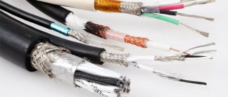
The following types of cables are used for aerial installation:
- SIP cable is a self-supporting insulated wire.
- Non-insulated, material - aluminum.
- Bare aluminum with steel core.
Ways to organize wiring inside the house
There are several options for performing internal wiring.
Connecting different cables inside
Welding the wire
The SIP conductor is broken and connected to the VVGng cable by twisting and strengthening by soldering. The technique is not reliable, as it can lead to fires.
Connecting various conductors with fittings
The coupling of SIP and VVGng is carried out using standard reinforcing bars, piercing clamps or other elements near the insertion point. It is unacceptable to use SIP in a residential area - it supports combustion processes.
Through the difavtomat
The connection diagram provides for the use of a two- or four-pole differential circuit breaker. The device is located in a separate sealed box. The cable is laid from the main line to the box and connected to VVGng in a corrugation.
To increase protection, a machine with a rating higher than the distribution board is used. This way, if there is a short circuit or overload, you can restore the line without leaving your home. Another device is installed outside, de-energizing the internal cable and preventing fire.
Electrical lines can be introduced into a residential building by air or underground. Before starting work, it is necessary to obtain permits and select a SIP cable and its cross-section.
How to choose the right section and brand of SIP
So what kind of cable should be used to bring electricity into the house? Many people resort to using SIP cable; it is allowed in many electrical industries and even in high voltage lines up to 35 kW.
This cable has its own design feature - phase wires, most often in the amount of three, wrap around the fourth - zero. Therefore, the appearance of SIP resembles a rope twisted into a spiral. High-quality LDPE or XLPE polyethylene is used to insulate conductors. These types of materials have high resistance and a long service life, which allows them to be used even with sudden temperature changes.
The core, which is located in the middle and has zero potential, is made of aluminum alloy. Sometimes the zero does not have its own insulation, which is required for phase conductors.
The SIP cable has one serious drawback - due to the presence of insulation, the cable is insufficiently cooled, so the current loads allowed are lower than those of uninsulated conductors. When choosing SIP, you should pay attention to insulation:
- With insulation made of thermoplastic polyethylene, temperature loads of up to 70 degrees are allowed. Suitable for this parameter: SIP-1, SIP-1A, SIP-4, SIPn-4.
- When choosing cross-linked polyethylene as an insulating material, temperature loads of up to 90 degrees are allowed. Overload mode indicators and short circuit current parameters also increase. Such performance characteristics have: SIP-2, SIP-2A, SIPs-4, SIP-3, PEV and PEVG.
The SIP cross-section is also determined by power consumption, the formula is presented above.
Selecting a single-phase electric meter
When choosing an electricity meter, we were guided by the following criteria:
- single-phase;
- rated (maximum) current;
- fastening method;
- operating principle of the device.
Since we live in a modern world, we therefore wanted to have a modern electricity meter with an electronic display. In the store we were offered a single-phase multi-tariff meter Energomera CE 102
Single-phase multi-tariff meter Energomera CE 102
It fully meets our selection criteria, here is a list of its characteristics:
- Accuracy class 1
- Number of tariffs 4
- Measuring network frequency, Hz 50±2.5
- Rated voltage, V 230
- Basic (maximum) current, A 5 (60); 10 (100)
- Starting current, mA 10; 20
- Parallel circuit power consumption, no more, V*A (W) 9 (0.8)
- Total power consumption of the series circuit, no more, V*A 0.1
- Operating temperature range, °C from minus 45 to plus 70
Connection diagram for Energomera CE 102 counter
Meter connection diagram
Cables for laying in the ground
When choosing a wire for underground input into a house, you should pay attention only to high-quality and reliable products, since a very common problem with such input is a breakdown to the ground.
Modern cables, made specifically for installation in the ground, have the following insulation:
- Pressed paper with special impregnation.
- Polyethylene.
- Polyvinyl chloride.
Very often they use VBBShV or PvBSHV conductors, which in addition to standard insulation have strip armor. AABL cable is also popular, but has a lower cost, since its shell is made of aluminum. Where there are risks of damage, PvKShp with wire mesh is most often used.
Electrical and wiring diagram
There is an electrical connection diagram, and there is a floor plan that matches the house plan.
The electrical diagram shows what types of connections are used - where the current is supplied in parallel, where in series, etc.
Electrical network diagram
For installation, you should also have a wiring diagram. In its simplest form, it should be a drawing that coincides with the plan of the entire house. It shows the location of the electrical wires and the places where the mounting units and connectors for the power supply are located.
Electrical wiring diagram
Here we see into which room the wires from the distribution board go, what brands of wires are used, how the sockets are located on the walls, etc.
Of course, the presented schemes are quite primitive. In reality, the power supply diagram can be quite complex. The project usually combines electrical and wiring diagrams.
How does electricity enter the house?
When introducing electricity into a private house, use one of the previously presented methods (laying a cable through the air on a cable or in the ground). When supplying electricity to a house, you must strictly follow the basic rule - the input cable should not have transits. The panel in which the consumer circuit will be presented should be located near the input cable for easier installation.
The conductor cannot be installed indoors directly through a hole in the wall. The hole must have additional protection; usually a metal pipe is used for this. The diameter of the pipe should be taken with a reserve, and the free space between the cable and the walls of the pipe should be sealed with cement mortar.
Administrative and legal nuances
The supply of electricity to a private home must be carried out by electricians with a certain access group.
To introduce electricity into the premises, the owner must obtain permits from the energy supply. The basis for the permit is the PVE project, which describes the internal electrical network in detail and provides calculations of consumer power. After this, the parameters of the allocated power and the consumer limit are set. According to the PVE, technical conditions are determined - connection method, communications features, engineering aspects.
Electrical distribution teams, the owner or a licensed contractor can connect the house to electricity.
Required documents
Example of a response to an application for technological connection
The property owner sends a request to the selected network organization. The company reviews the application within 15 days. After a positive response, the following documents are prepared:
- application for technical connection in a unified form;
- diagram of power receivers;
- copies of documents on the right to a building or land plot;
- an application indicating the citizen’s full name, passport details, location of receivers, time frame for creating the project and putting the line into operation, name of the provider, permit for construction work.
After reviewing the documents, the energy provider sends a contract with technical conditions. The applicant remains to sign it and send it to representatives of the network organization.
If the site meets the requirements of the technical conditions, work on its territory is carried out at the expense of the owner. Events outside the allotment are paid for by the network company. Upon completion, the energy sales company connects the premises to the network after a control inspection.
How to make the correct air injection
When introducing a cable into a house from a nearby line or pole, you should invite specialists. To attach it to the wall, you must use special overhead brackets (especially when installing it in a wooden house). This will allow you to securely fix it and not damage the insulation. At a certain distance from the wall, a slight deflection of the cable should be made in order to prevent rainwater from entering the room.
The cable on which the cable is attached must not be overtightened on the supports, since during sudden and frequent temperature changes (which occur during cold periods of the year), it can become deformed.
Advantages of SIP
A SIP type cable includes several cores, combined by twisting into a single structure. The entire surface of this bundle is covered with insulation, which is cross-linked or thermoplastic polyethylene.
The technical capabilities of SIPs allow us to achieve better technical performance in comparison with old type wires (A or AC). Legacy cables did not use an insulating layer, but rather each core was installed individually using dedicated insulators located on the crossarms. In SIP, the device is much simpler, since the harness pre-tensioned by a winch is simply fixed to the support.
SIPs can even be installed on walls, which was impossible with the old type of wires. This feature is especially important in urban conditions, since it becomes possible to use short supports and install cables near low-current lines.
SIP allows you to save material and technical resources. For example, such a cable does not require wide forest clearings for power lines, as is the case with old-style wires. In addition, SIPs are reliable: such wires are less susceptible to breaks and overlaps, and therefore to short circuits. And the SIP structure itself is stronger: breaking four tightly twisted wires is not easy.
SIP is resistant to moisture, low temperatures and temperature changes. If an ice crust inevitably forms on ordinary wiring in winter (resulting in broken lines), then the SIP wires are protected by an insulating layer that prevents icing of the material.
The only exception to the above is the two-core modification SIP-1, in which the load-bearing conductor is not covered with insulation. In other cables, the supporting conductors are either inside the bundle (SIP-4) or insulated.
It should be said that SIP has become a technical standard: all energy sales organizations require the use of this particular type of cable to organize new connections.
One of the motivations of marketers: SIP allows you to avoid unauthorized connections (in other words, theft of electricity), which is easy to organize in the case of uninsulated wiring.
In addition, thanks to special devices, it is possible to arrange branches from the main cable without turning off the power. This possibility is provided by the presence of an insulating layer. Consequently, another advantage of SIP is operational safety.
And, finally, another advantage of SIP is the smallest losses among competitors when transporting energy over long distances. This is achieved by low reactance (for old type cables this figure is three times higher).
Some examples of input cable protection
The best protection for the input cable is its insulation and the method of laying it in a place where no one can reach it. This can be a method of laying underground or by air. To prevent the harmful effects of natural conditions, the conductor can be laid in a special PVC pipe, but few do this, due to the significant increase in the cost of the structure.
To protect the wire in the wall, it is best to use a metal pipe. A replacement for metal can be PVC, which has a more affordable price.
The Importance of Electrical Network Planning
As in any business, when laying electrical networks, first of all, you cannot do without a detailed plan. First of all, this is accounting for all consumers (light bulbs, washing machines, refrigerators, etc.). Secondly, a graphical display of the electrical wiring system from source to consumer.
All stages of installing electrical networks are based on the electrical connection diagram. In general, this is a drawing that clearly shows:
- Power supply units from the input line
- Short circuit protection devices
- Distribution boxes where power lines branch off to certain premises and consumers
- Location of power lines - that is, wires
- Places where sockets for consumers are installed
The plan diagram must necessarily include information about the power of consumers, the parameters of fuses, the parameters of electrical wires and similar information.
Only having the connection diagram in hand can you begin work. A haphazard installation of wires will certainly lead to errors, and errors in working with electricity are a direct threat to the safety of life and home.
If the house was built according to an individual project, then the connection diagrams should be drawn up specifically for this house. If a standard project is used, the electrical connection diagram can also be standard.
Cable entry underground
A wire laid underground does not require fastening to the wall; in this case, the conductor is laid through the foundation. The part of the cable that comes out of the ground must be protected using a metal tube or a thick PVC conduit.
To lay a cable in the ground, a trench must be made, at least 70 cm deep. At the bottom of the trench, a sand “cushion” is made, 15–20 cm thick. The cable is laid on it and closed with earth on top. Underground cable entry is a labor-intensive process, but more durable than overhead entry.
Video description
This video shows how to lay the lead-in wire in a trench:
It is necessary to lay the cable through the wall in a metal pipe at a slight angle (protection from water). For a 15 kW power network with this type of connection, it is recommended to use copper VBBShb with a cross-section of 10 mm². It is necessary to avoid crossing the electrical network with water supply lines and gas pipes under the house.
The recess must be placed parallel to the foundation at a distance of 60 cm, and in places where cars pass, the wire must be at a depth of 1.25 m and protected by a pipe. The advantage of this type of connection is the high protection of the cable from external mechanical damage and wear from weather conditions.
The disadvantage of such a connection is that it is labor-intensive and expensive, as well as the inability to quickly replace damaged areas.
Wire that is laid through the wall Source i.ytimg.com
How to supply electricity to a distribution panel
When using an ordinary conductor, it is enough to simply connect it to the main circuit breaker, from which the electricity will then go to other consumers. But when using an SIP or an insulated conductor, you should install a switching unit - a separate place for the transition of the input cable to the one that will be routed to the panel.
It is most convenient to use a branch clamp for this - 2 copper plates, fastened to each other with four bolts and placed in a special plastic box.
Electrical Security
Ensuring the safety of using electricity is perhaps a more important task than even the electricity supply itself. The danger of electricity lies in its current-damaging ability in relation to humans and in the fire hazard - due to the extreme heating of the wires during a short circuit.
This topic is quite extensive. As for the power supply circuit, the main thing in its design is to ensure the safe operation of the electrical network.
Particular attention should be paid to the compliance of the mounted machines with those indicated on the diagram. The power of the machines must be carefully calculated taking into account all the loads on the network and each of its nodes.
With regard to human safety, the wiring diagram provides for a number of measures:
- Presence of electrical insulation on all live parts
- Correct placement of sockets
- Grounding of all necessary elements
- Inaccessibility of most electrical components for accidental contact
- Increased network protection in children's rooms
- Application of special measures for protection in wet areas
8. Installation of the electrical network according to the connection diagram
Electrical installation must be carried out strictly according to the diagram and using the materials specified in it. Under no circumstances should you install machines that do not comply with the design. It is impossible to arbitrarily underestimate the cross-section of wires. You cannot be careless about the connection points of the wires.
Often, would-be craftsmen simply twist two or more wires, not caring that a loose connection is where the wires overheat or spark. It is unacceptable to twist wires made of different metals, for example, aluminum and copper. All connections must be made in special junction boxes.
Wiring on bends is only possible at right angles, otherwise it will be impossible to determine where the hidden wire is located if you suddenly have to drill into the wall.
Laying of wires must be strictly horizontal or vertical
There are many such rules, we will talk about them in more detail in other articles.
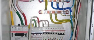
What is an input device cabinet
The input device can be briefly classified as all switching and other power control devices that are installed directly at the main line input. For ease of installation of such devices, special cabinets are used, which have special fastenings.
In the input device cabinets the following can be located:
- circuit breakers;
- switches;
- circuit breakers;
- counters.
- measuring instruments.
Power distribution across premises
As we have already mentioned, the most energy-intensive rooms can be considered
- A kitchen where a good housewife uses a lot of electrical appliances...
- Bathroom and laundry room with washing machine and electric heater
- Boiler room, where the heaters are heated during electric heating of the house
Can be quite energy intensive
- A workshop where a craftsman uses powerful power tools
- A living room with many lamps installed, a TV and a couple of computers on
The most economical consumers of electricity are
- Bedrooms, children's
- Bathrooms
- Utility rooms – pantry, dressing room, corridor
- Attic and basement, where the owner looks relatively rarely
Obviously, for each group of premises a machine of the appropriate power is installed.
The law regulating the standards for connecting a plot of land and a private house to electricity
- The main document regulating the economic relations between electricity suppliers and its consumers and establishing the powers of government bodies to regulate these relationships is the Federal Law of March 26, 2003 N 35-FZ (as amended on December 27, 2019) “On Electric Power Industry”.
- In accordance with Art. 20-26 of this law, “Rules for the technological connection of power receiving devices” were developed, which were approved by the Government of the Russian Federation in Resolution No. 861 of December 27, 2004.
- Also, the actions of network organizations fall under the scope of the Federal Law of July 26, 2006 N 135-FZ “On the Protection of Competition”, since these organizations are subjects of a natural monopoly.
Tools and materials for work
To install electrical wiring you will need the following:
- scissors, pliers, screwdrivers;
- screwdriver; grinder with diamond blade, wall chasers;
- hammer, mounting chisel;
- spatula and materials for sealing walls - alabaster, gypsum;
- fasteners;
- wires and cables of the required section;
- sockets, switches, socket boxes;
- circuit breakers, RCDs, distribution boxes;
- connecting terminals.
To work with electrical wiring, it is better to take a tool with rubber handles.
Installation of internal wiring
Electrical wiring in a country house is installed exactly according to the calculated diagram. You can’t replace something at the last moment and not take into account the difference in load. Installation is carried out in a certain order.
Marking
It is necessary to mark on the wall the location of all electrical points .
Use chalk and pencil. The location is chosen taking into account the standards of SNiP, PUE and your own convenience. It is recommended to immediately mark the location of the wire . After this, it is easier to calculate how much cable is actually required. The wiring is pulled along the walls. It is allowed to lay conductors on the floor if it is filled with cement screed and in this case the wire must be hidden in a corrugation to prevent mechanical damage.
Wall chipping
If installation is carried out openly or in a protective corrugation, it is enough to simply mark the position of the wiring on the wall.
If you want to hide the cable, you need to make grooves in the walls of the required depth and width - grooves. This can be done using a hammer drill with a chisel attachment, an angle grinder or a wall chaser, whatever you have on hand.
The marking lines mark the width of the groove. Usually it coincides with the depth. Using a wall chaser or a grinder with a disk cut the material along the boundaries of the groove ; if this is not enough for removal, make several more cuts inside the groove. Then take out the material and trim the groove with a chisel and hammer.
For sub-grids and junction boxes, holes in the wall are drilled with crowns - diamond or carbide-tipped. The standard sizes for the socket box are diameter 68 mm and depth 45 mm. But if non-standard types of modules are used, the dimensions of the holes will be different.
If modules with several sockets and switches are installed, several holes are drilled in a row, and the partitions between them are knocked out with a hammer drill or chisel.
Laying lines
At the dacha, wiring is most often installed in an open way. It is not necessary to use corrugation if you take a fairly well-insulated cable - VVG or VVGng, for example. To achieve a more aesthetic appearance, it is recommended to hide the wiring under the baseboard - floor or ceiling.
When laying hidden, the wiring is placed in grooves and fixed in them with putty, alabaster or special staples. The groove is filled completely with material.
Installation of junction boxes and sub-grids
Distribution boxes and socket boxes are mounted after laying the wires. Instructions are followed.
- Holes are drilled in the socket box for the power cable and auxiliary wires.
- The landing hole is coated with alabaster. Check: when you press on the bottom, the nest should not fall through.
- Coat it with alabaster on the outside of the socket box and insert it into the hole. The socket box should hold tightly. Alabaster dries in 2 hours, after which work can continue.
The distribution box can also be placed on alabaster. If the walls of the house are wooden, the shield is secured with screws and dowels.
Line connection
The connection of the socket and switch is carried out after finishing work, if any was carried out.
- In the junction box they find the zero, phase and supply wire of the circuit. The veins come in different colors, so it's easy.
- From a group of cables, find the one that is led from the installation site of the socket, switch, equipment and strip the ends. The cable cores are screwed into phase, neutral and power. Close the shield.
- Then the end of the cable that goes to the socket is cut into cores and the ends are stripped. The phase is connected to the first terminal of the socket, and the neutral to the second. The ground connection is connected to the connector in the middle of the socket.
- Insert the socket into the socket box, fix it with self-tapping screws and screws through the tabs. Then the decorative part is attached.
All connection and installation work is carried out when the power supply is disconnected.
Final work
The final stage is testing the electrical network . They check not only the fully assembled wiring, but also as the circuits are installed.
- Each line is checked using a tester before connecting to the panel. Make it yourself from 2 pieces of wire, a socket and a low-power light bulb. The neutral and grounding of the line are connected to the panel directly, and the phase is connected in series through the control panel. If the light does not light up when you turn on the machine, everything is in order.
- If the light turns on, there is a short circuit on the line. It is necessary to turn off the machine and find the cause of the breakdown.
- Check each outlet, connecting a load to each. Each lamp needs to be ringed.
- The switches are closed - all the wires for them are connected and short-circuited.
- Then the entire group is loaded to the maximum to check the operation of the circuit breaker.
To make a test, you will need a special device - a multimeter or tester.