How to visually determine the identity of the wires in a socket
Painting core insulation in specific colors is a way of marking electrical wires. This is done to visually determine the purpose of a particular conductor. This method of determining the purpose is the most visual and convenient for electricians. Manufacturers also apply letter markings. It is also marked in electrical circuits or on devices.
The marking of electrical wires does not have strict regulations, so the colors may not match.
In single-phase current networks
Electrical wiring with a single-phase 220 V network has 2 cores. One is phase, the other is zero. The color coding is usually as follows:
- phase – brown, black, gray, red, turquoise or other color;
- zero – blue.
According to generally accepted markings, the phase conductor can be painted in any color except blue. The zero core is traditionally painted blue or light blue.
A single-phase three-wire network has 3 cores. There is a neutral, phase and grounding conductor. The presence of grounding is one of the main requirements in the installation rules.
The marking of the phase electrical wire is brown, the neutral wire is blue or light blue, the ground wire is yellow-green.
In three-phase current networks (three-wire)
A three-phase 380 V network can be with or without a grounding conductor.
There are three-phase four-wire and five-wire networks. A network with four conductors contains 3 phase conductors and one zero working conductor. There is no grounding.
The neutral conductor is necessarily indicated in blue or cyan; any other color can be used for the phase.
The five-wire network is grounded. It is traditionally indicated by a yellow-green color. The coloring of the remaining wires is similar: zero is blue, phases are of other colors. Typically, phase conductor A is brown, B is black, and C is gray.
electrical safety
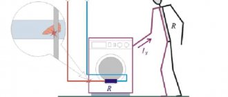
Alternating electricity with a voltage of 380V - 220V is a dangerous factor, so if a person touches exposed wires or metal parts of electrical equipment that may be under this voltage without permission, it can result in severe burns or fatal injury!
For this purpose, the PUE gives an answer not only to the questions: what color is the grounding wire, or what is PEN, but what is it for. In order to protect people as much as possible from possible exposure to electric current, electrical safety systems were adopted, characterized by one or more factors, such as:
- grounding;
- protective grounding;
- separation of networks by a transformer.
To ensure safe operation in existing electrical installations up to 1 kV, five grounding systems are used: TN-C, TN-S, TN-C-S, TT, IT with different methods of grounding, grounding and separation of networks. The PUE defines each of the systems as:
- TN-C, where the working zero N and the grounding PE conductors are combined in one PEN wire. Characterized by: the use of a cable with four cores in a three-phase network and a two-core cable in a single-phase network. This is the oldest device in electrical networks and is still found everywhere for reasons of economy, for example, in street lighting.
- TN-S, where the working N conductor and the grounding PE are separated from the supply transformer to the end consumer. Such networks are made of five-core cables for a three-phase network and three-core wires for a single-phase network.
- TN-C-S, where there is one combined PEN conductor of a four-core cable, from the supply transformer to the group panel at the entrance to the building, which is further divided into N and PE, respectively into five and three-wire wiring. This is the most common system for constructing power supply networks for buildings and structures.
- TT, where there is only one working N conductor, and only the electrical equipment body is grounded. In such a system, four and two-wire wiring are used, respectively. This is how overhead power lines are mainly constructed.
- IT, where the electrical installation is separated from the power supply network by a transformer and completely isolated from the ground. This is the safest system for humans and is used only for special-purpose consumers.
Thus, the color of the wires phase and zero, L and N in electrics will help to clearly determine the security system used in a given electrical network.
What is the difference between phase and zero?
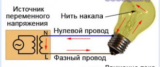
The AC network is divided into two components: the working phase and zero. The phase is supplied with operating voltage. Zero is necessary to create a continuous electrical network. A grounding conductor is also used. It is intended to protect people from electric shock.
Modern homes use a three-phase electricity supply system, consisting of three phases and one neutral. In each phase, the supplied current shifts by 120 degrees. The neutral conductor compensates for uneven load. In its absence, a different voltage is created at each load, which leads to breakdown of electrical equipment.
Color of zero, neutral
The “zero” wire should be blue
. In the distribution board it must be connected to the zero bus, which is designated by the Latin letter N. All blue wires must be connected to it. The bus is connected to the input via a meter or directly, without additional installation of the machine. In the distribution box, all wires (except for the wire from the switch) of blue color (neutral) are connected and do not participate in switching. To the sockets, the blue “zero” wires are connected to the contact, which is designated by the letter N, which is marked on the back of the sockets.
The designation of the phase wire is not so clear. It can be either brown, or black, or red, or other colors except
blue, green and yellow. In an apartment switchboard, the phase wire coming from the load consumer is connected to the lower contact of the circuit breaker or to the RCD. In switches, the phase wire is switched; during switching off, the contact closes and voltage is supplied to consumers. In phase sockets, the black wire must be connected to the contact marked with the letter L.
How to find ground, neutral and phase in the absence of a designation
If there is no color marking of the wires, then you can use an indicator screwdriver to determine the phase; upon contact with it, the screwdriver indicator will light up, but not on the neutral and ground wires.
You can use a multimeter to find ground and neutral. We find the phase with a screwdriver, fix one contact of the multimeter on it and “probe” the wires with another contact; if the multimeter shows 220 volts, this is neutral; if the values are below 220, then it is grounding.
Letter and numeric wire markings
The first letter “A” denotes aluminum as the core material; in the absence of this letter, the core is copper.
The letters “AA” denote a multi-core cable with an aluminum core and an additional braid made of it.
"AC" is indicated in case of additional lead braiding.
The letter “B” is present if the cable is waterproof and has an additional double-layer steel braid.
“BN” cable braid does not support combustion.
"B" polyvinyl chloride shell.
"G" does not have a protective shell.
“g” (lowercase) bare, waterproof.
“K” is a control cable wrapped with wire under the top sheath.
"R" rubber casing.
"NR" non-flammable rubber casing.
Designations and explanation
Conductors have not only color, but also letter markings.
Latin letters indicate the corresponding cores in circuits and equipment. Additional information may also be indicated on the cable: cross-section, length, brand and other necessary parameters.
Phase wire L
The letter designation of the phase conductor is written as L (line). If there are several phases, a number next to the letter is additionally noted - L1, L2. The color of the phase cable can be anything except blue (cyan) and yellow-green.
Zero worker N
The letter N (neutral) denotes the neutral or middle conductor. It is painted in blue shades. Until 2000, the color marking of the zero was white.
Zero protective PE
The Latin letters PE (protect earth) represent the neutral grounding conductor. The designation PEN is also found - this is typical for the classic combination of wires, biased to zero. Similar markings are found in TN-CS systems. The color of the vein is yellow-green.
Color of zero, neutral
The “zero” wire should be blue
. In the distribution board it must be connected to the zero bus, which is designated by the Latin letter N. All blue wires must be connected to it. The bus is connected to the input via a meter or directly, without additional installation of the machine. In the distribution box, all wires (except for the wire from the switch) of blue color (neutral) are connected and do not participate in switching. To the sockets, the blue “zero” wires are connected to the contact, which is designated by the letter N, which is marked on the back of the sockets.
The designation of the phase wire is not so clear. It can be either brown, or black, or red, or other colors besides
blue, green and yellow. In an apartment switchboard, the phase wire coming from the load consumer is connected to the lower contact of the circuit breaker or to the RCD. In switches, the phase wire is switched; during switching off, the contact closes and voltage is supplied to consumers. In phase sockets, the black wire must be connected to the contact marked with the letter L.
How to find ground, neutral and phase in the absence of a designation
If there is no color marking of the wires, then you can use an indicator screwdriver to determine the phase; upon contact with it, the screwdriver indicator will light up, but not on the neutral and ground wires.
You can use a multimeter to find ground and neutral. We find the phase with a screwdriver, fix one contact of the multimeter on it and “probe” the wires with another contact; if the multimeter shows 220 volts, this is neutral; if the values are below 220, then it is grounding.
Letter and numeric wire markings
The first letter “A” denotes aluminum as the core material; in the absence of this letter, the core is copper.
The letters “AA” denote a multi-core cable with an aluminum core and an additional braid made of it.
"AC" is indicated in case of additional lead braiding.
The letter “B” is present if the cable is waterproof and has an additional double-layer steel braid.
“BN” cable braid does not support combustion.
"B" polyvinyl chloride shell.
"G" does not have a protective shell.
“g” (lowercase) bare, waterproof.
“K” is a control cable wrapped with wire under the top sheath.
"R" rubber casing.
"NR" non-flammable rubber casing.
Wire colors abroad
The color marking of wires in Ukraine, Russia, Belarus, Singapore, Kazakhstan, China, Hong Kong and the countries of the European Union is the same: Ground wire - Green-yellow
Neutral wire - blue
phases are marked with different colors
The neutral designation is black in South Africa, India, Pakistan, England, but this is the case with old wiring.
Currently the neutral is blue.
In Australia it can be blue and black.
In the USA and Canada it is designated white. You can also find gray labeling in the USA.
The ground wire is yellow, green, yellow-green in color everywhere, and in some countries it may also be without insulation.
Other wire colors are used for phases and may be different, except for the colors indicating other wires.
13 ways to save electricity
Colorless flat three-core wires when installing PPV: how to determine?
It is possible to determine the phase and neutral conductors not by markings.
This is done using an indicator screwdriver or a multimeter. Finding a phase core using an indicator is quite simple. You need to touch the controlled section of the circuit with the conductive tip of a screwdriver.
You need to touch the contact pad with your finger. If the indicator lights up, then the tested core is a phase. Otherwise it is zero.
It is prohibited to hold onto the metal part of the screwdriver when checking!
Checking with a multitester is labor-intensive, but it provides complete information. To find the phase, you will need a natural grounding conductor - a heating radiator, a metal pipe. The multimeter is switched to AC voltage measurement mode. The limit is above 220 V. Touch the conductor with one tester probe and the ground electrode with the other. When the display shows a voltage close to the mains voltage (220 V), then the phase conductor has been found.
The multimeter shows that there is no phase. This is due to the fact that the circuit is open. When closed, the phase will appear.
The multimeter also finds the neutral and ground conductors. To do this, it is first determined where the phase is located.
Move the tester to the position of checking alternating voltage with a limit above 220 V. In turn, you need to measure between a phase and another conductor. The larger number is the value between the phase and the working zero, the smaller number is between the phase and ground conductor. This method is rarely used; it is better to find the ground by marking and connecting to the ground contacts.
You can also find the phase cable using a light bulb by screwing it into the socket. Find 2 pieces of electrical wires with bare ends - one is grounded. Touch the wire with the other end. If the lamp lights up, then this is the working phase.
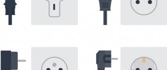
Types of sockets with grounding contact
Grounded sockets are distinguished according to several criteria:
- According to the installation method - external (open or hidden wiring), internal (hidden).
- Connected load power: power and standard. Powerful devices are connected through power devices; they can pass large currents. But this makes them look a little rough. For installation, they try to choose a place so that such an outlet is not conspicuous.
- According to the degree of protection - for internal (indoors) or external installation (outdoors).
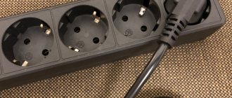
- Number of sockets: with one, two, three or more connectors. If there are more than three connectors, the product is called a socket block. Can be combined with a switch.
In general, there are different models of grounded sockets. For example, with lids. They are placed on the street. Covers are needed to protect the contact sockets from clogging, flooding and snow. You can see them in the house too. But here such models are installed mainly to block access for children. There are even covers on sockets that can be locked with a key. They can, again, be used as protection against children, or as protection against unauthorized connections.
They come with all sorts of bells and whistles
Sockets with curtains can also be useful - this is a substitute for a cover. In them, small pieces of plastic are attached using springs, closing the connectors. The curtains protect the connectors from dust and serve as some kind of protection from children. Still, it’s harder to plug a foreign object into the socket, since they move away only if you press both curtains at once.
Why is it impossible to determine phase and zero by wire color?
According to the requirements of the PUE, conductors have their own color marking.
It is not recommended to rely 100% on this method of determination. The cables may have been mixed up at the factory, so we recommend checking them. When doing the work yourself, you can mark the purpose of the wires, especially if they are colorless.
To do this, you need to purchase heat-shrinkable tubes or electrical tape of different colors. In accordance with the rules, it is allowed to do independent marking not along the entire length of the electrical wire, but only at the connection points. The tube or insulating tape must be secured to the corresponding conductor and write down which color belongs to which conductor.
Requirements
Requirements for the grounding wire are made in accordance with the local conditions in which electrical installations are operated. They may also differ in accordance with the assigned tasks or operating mode. All requirements can be divided according to the following parameters of grounding wires:
- Single-core or stranded - used depending on the specific equipment. Thus, stranded wires should be installed in areas where a certain level of flexibility is required and the ground must be easy to move (cell doors, test equipment, etc.). Single-core wires provide rigid fixation and are attached to the housings of stationary equipment.
- Presence or absence of insulation - an insulating layer is required when laying openly or along equipment casings.
- Separately laid or located as part of a solid cable - with a combined design in single-phase systems it should be carried out with a three-core cable, and in three-phase systems with a five-core cable. If the system is already installed, it must be carried out with a separate grounding conductor.
- The material of the conductive element (copper, aluminum, steel) determines the resistivity of the conductor itself and its chemical resistance to various environmental influences. Copper conductors are the most resistant to corrosion and have the lowest resistivity, followed by aluminum and steel.
The most important requirement for the grounding loop and the conductor connected to it is the total ohmic resistance. Which is determined by the cross-section of the ground wire, and the transition resistance between the circuit blades and the ground, and the places of bolted (terminal) or welded connections in the common circuit. The total value of the circuit resistance is determined by clauses 1.7.101 - 1.7.103 of the PUE, depending on the linear or phase voltage of the electrical installation and its type, these parameters are given in the table below:
Table: grounding resistance value
| Type of grounded electrical installation | Line voltage value Ul, V | Phase voltage value Uph, V | Grounding resistance R, Ohm no more |
| Connection points for neutrals of generators, transformers and other current sources | 660 | 380 | 2 |
| 380 | 220 | 4 | |
| 220 | 127 | 8 | |
| Connection points located near the connection points of neutrals of generators, transformers and other current sources | 660 | 380 | 15 |
| 380 | 220 | 30 | |
| 220 | 127 | 60 | |
| Places for repeated grounding of overhead lines and supply lines | 660 | 380 | 15 |
| 380 | 220 | 30 | |
| 220 | 127 | 60 |
Is ground always indicated by a green-yellow wire?
Current generally accepted standards require that the ground be marked yellow-green.
It looks like yellow insulation with longitudinal bright green stripes. Sometimes there is a coloration of transverse stripes. Sometimes the grounding electrical wire is marked with a yellow or green tint. A similar designation should be on the diagram.
Conductors manufactured before 2000 were color coded differently. According to it, grounding was indicated in black.
Identification of electrical wires is a mandatory step before starting electrical installation work. If you confuse the phase, neutral and grounding conductors, equipment failure, electrical wiring failure, or even a fire in the apartment may occur. There are several ways to find out which core is responsible for what. The first is based on the color of the conductor insulation. This is a common method. The second is by letter marking. If the electrical wire is colorless, you can find out the purpose of the wires using an indicator screwdriver, a multimeter or a light bulb.
Color of zero, neutral
The “zero” wire should be blue
. In the distribution board it must be connected to the zero bus, which is designated by the Latin letter N. All blue wires must be connected to it. The bus is connected to the input via a meter or directly, without additional installation of the machine. In the distribution box, all wires (except for the wire from the switch) of blue color (neutral) are connected and do not participate in switching. To the sockets, the blue “zero” wires are connected to the contact, which is designated by the letter N, which is marked on the back of the sockets.
The designation of the phase wire is not so clear. It can be either brown, or black, or red, or other colors besides
blue, green and yellow. In an apartment switchboard, the phase wire coming from the load consumer is connected to the lower contact of the circuit breaker or to the RCD. In switches, the phase wire is switched; during switching off, the contact closes and voltage is supplied to consumers. In phase sockets, the black wire must be connected to the contact marked with the letter L.
How to find ground, neutral and phase in the absence of a designation
If there is no color marking of the wires, then you can use an indicator screwdriver to determine the phase; upon contact with it, the screwdriver indicator will light up, but not on the neutral and ground wires.
You can use a multimeter to find ground and neutral. We find the phase with a screwdriver, fix one contact of the multimeter on it and “probe” the wires with another contact; if the multimeter shows 220 volts, this is neutral; if the values are below 220, then it is grounding.
Letter and numeric wire markings
The first letter “A” denotes aluminum as the core material; in the absence of this letter, the core is copper.
The letters “AA” denote a multi-core cable with an aluminum core and an additional braid made of it.
"AC" is indicated in case of additional lead braiding.
The letter “B” is present if the cable is waterproof and has an additional double-layer steel braid.
“BN” cable braid does not support combustion.
"B" polyvinyl chloride shell.
"G" does not have a protective shell.
“g” (lowercase) bare, waterproof.
“K” is a control cable wrapped with wire under the top sheath.
"R" rubber casing.
"NR" non-flammable rubber casing.
Wire colors abroad
The color marking of wires in Ukraine, Russia, Belarus, Singapore, Kazakhstan, China, Hong Kong and the countries of the European Union is the same: Ground wire - Green-yellow
Neutral wire - blue
phases are marked with different colors
The neutral designation is black in South Africa, India, Pakistan, England, but this is the case with old wiring.
Currently the neutral is blue.
In Australia it can be blue and black.
In the USA and Canada it is designated white. You can also find gray labeling in the USA.
The ground wire is yellow, green, yellow-green in color everywhere, and in some countries it may also be without insulation.
Other wire colors are used for phases and may be different, except for the colors indicating other wires.
13 ways to save electricity


