One of the elements of an electrical circuit that has a constant (certain) value of resistance to electric current is a constant resistor. Translated from Latin, resisto means “I resist.” With the help of such a part, a linear transformation of current (I) into voltage (U) and vice versa occurs. A resistive element can limit the amount of current and absorb electrical energy. Variable resistors allow you to manually vary the value of their resistance.
Variable resistors, appearance
Code and color marking of resistors
The coded designation of the nominal resistance of resistors consists of three or four characters, including two numbers and a letter or three numbers and a letter. The code letter is a multiplier indicating the resistance in Ohms and determines the position of the decimal point. The coded designation of the permissible deviation consists of a letter of the Latin alphabet (see tables).
Coded designation of nominal resistance, tolerance and designation examples.
| Notation examples | |
| Full designation | Code |
| 3.9 ohms ± 5% | 3R9J |
| 215 ohms ± 2% | 215RG |
| 1 kΩ ± 5% | 1K0J |
| 12.4 kΩ ± 1% | 12K4F |
| 10 kΩ ± 5% | 10KJ |
| 100 kΩ ± 5% | M10J |
| 2.2 MΩ ± 10% | 2M2K |
| 6.8 GΩ ± 20% | 6G8M |
| 1 Volume ± 20% | 1T0M |
| Resistance | |
| Factor | Code |
| 1 | R(E) |
| 10^3 | K(K) |
| 10^6 | M(M) |
| 10^9 | G (G) |
| 10^12 | T (T) |
| Tolerance, % | Code |
| ± 0,001 | E |
| ± 0,002 | L |
| ± 0,005 | R |
| ± 0,01 | P |
| ± 0,02 | U |
| ± 0,05 | A |
| ± 0,1 | B (W) |
| ± 0,25 | C (U) |
| ± 0,5 | D (D) |
| ± 1 | F (P) |
| ± 2 | G (L) |
| ± 5 | J (I) |
| ± 10 | K (C) |
| ± 20 | M(V) |
| ± 30 | N (F) |
Note. The old designation is indicated in parentheses.
Color marking is applied in the form of four or five colored rings. Each color corresponds to a specific digital value.
For resistors with four colored rings, the first and second rings indicate the resistance value in Ohms, the third ring is the multiplier by which the nominal resistance value must be multiplied, and the fourth ring determines the tolerance value in percent.
| Sign color | Nominal resistance, Ohm | Tolerance, % | TKS [ppm/°C] | |||
| First digit | Second digit | Third digit | Factor | |||
| Silver | 10-2 | ±10 | ||||
| Golden | 10-1 | ±5 | ||||
| Black | 0 | 0 | 1 | |||
| Brown | 1 | 1 | 1 | 10 | ±1 | 100 |
| Red | 2 | 2 | 2 | 102 | ±2 | 50 |
| Orange | 3 | 3 | 3 | 103 | 15 | |
| Yellow | 4 | 4 | 4 | 104 | 25 | |
| Green | 5 | 5 | 5 | 105 | 0,5 | |
| Blue | 6 | 6 | 6 | 106 | ±0,25 | 10 |
| Violet | 7 | 7 | 7 | 107 | ±0,1 | 5 |
| Grey | 8 | 8 | 8 | 108 | ±0,05 | |
| White | 9 | 9 | 9 | 109 | 1 | |
Note. Ppm – parts per million – part per million, number of parts per million, 1/106
Resistors with a small tolerance value (0.1%...2%) are marked with five color rings. The first three are the numerical value of the resistance, the fourth is the multiplier, the fifth is the tolerance. In the marking of resistors adopted on (see below), the last ring can be TKS.
The markings on the resistors are shifted to one of the terminals and are located from left to right. If the dimensions of the resistor do not allow the marking to be placed closer to one of the terminals, the width of the stripe of the first sign is made approximately twice as large as the others. However, this requirement is not always met; in this case, we try to determine the denomination, the value of which falls into the standard series:
The nominal resistance of resistors is selected from six standard rows (E3, E6, E12, E24, E48, E96 and E192) in accordance with GOST 2825-67.
Each row corresponds to a certain tolerance in the part ratings. Thus, parts from the E6 series have a permissible deviation from the nominal value of ±20%, from the E12 series - ±10%, from the E24 series - ±5%. Actually, the rows are arranged in such a way that the next value differs from the previous one by slightly less than double tolerance. Nominal ranges E6, E12, E24
| E6 | E12 | E24 | E6 | E12 | E24 | E6 | E12 | E24 | ||
| 1,0 | 1,0 | 1,0 | 2,2 | 2,2 | 2,2 | 4,7 | 4,7 | 4,7 | ||
| 1,1 | 2,4 | 5,1 | ||||||||
| 1,2 | 1,2 | 2,7 | 2,7 | 5,6 | 5,6 | |||||
| 1,3 | 3,0 | 6,2 | ||||||||
| 1,5 | 1,5 | 1,5 | 3,3 | 3,3 | 3,3 | 6,8 | 6,8 | 6,8 | ||
| 1,6 | 3,6 | 7,5 | ||||||||
| 1,8 | 1,8 | 3,9 | 3,9 | 8,2 | 8,2 | |||||
| 2,0 | 4,3 | 9,1 |
The E48 series corresponds to a relative accuracy of ±2%, E96 - ±1%, E192 - ±0.5%.
The elements of the series form a strict geometric progression with denominators 101/48 ≈ 1.04914, 101/96 ≈ 1.024275, 101/192 ≈ 1.01206483 and can easily be calculated on a calculator. Nominal series E48, E96, E192
| E48 | E96 | E192 | E48 | E96 | E192 | E48 | E96 | E192 | E48 | E96 | E192 | E48 | E96 | E192 | E48 | E96 | E192 | |||||
| 1,00 | 1,00 | 1,00 | 1,47 | 1,47 | 1,47 | 2,15 | 2,15 | 2,15 | 3,16 | 3,16 | 3,16 | 4,64 | 4,64 | 4,64 | 6,81 | 6,81 | 6,81 | |||||
| 1,01 | 1,49 | 2,18 | 3,20 | 4,70 | 6,90 | |||||||||||||||||
| 1,02 | 1,02 | 1,50 | 1,50 | 2,21 | 2,21 | 3,24 | 3,24 | 4,75 | 4,75 | 6,98 | 6,98 | |||||||||||
| 1,04 | 1,52 | 2,23 | 3,28 | 4,81 | 7,06 | |||||||||||||||||
| 1,05 | 1,05 | 1,05 | 1,54 | 1,54 | 1,54 | 2,26 | 2,26 | 2,26 | 3,32 | 3,32 | 3,32 | 4,87 | 4,87 | 4,87 | 7,15 | 7,15 | 7,15 | |||||
| 1,06 | 1,56 | 2,29 | 3,36 | 4,93 | 7,23 | |||||||||||||||||
| 1,07 | 1,07 | 1,58 | 1,58 | 2,32 | 2,32 | 3,40 | 3,40 | 4,99 | 4,99 | 7,32 | 7,32 | |||||||||||
| 1,09 | 1,60 | 2,34 | 3,44 | 5,05 | 7,41 | |||||||||||||||||
| 1,10 | 1,10 | 1,10 | 1,62 | 1,62 | 1,62 | 2,37 | 2,37 | 2,37 | 3,48 | 3,48 | 3,48 | 5,11 | 5,11 | 5,11 | 7,50 | 7,50 | 7,50 | |||||
| 1,11 | 1,64 | 2,40 | 3,52 | 5,17 | 7,59 | |||||||||||||||||
| 1,13 | 1,13 | 1,65 | 1,65 | 2,43 | 2,43 | 3,57 | 3,57 | 5,23 | 5,23 | 7,68 | 7,68 | |||||||||||
| 1,14 | 1,67 | 2,46 | 3,61 | 5,30 | 7,77 | |||||||||||||||||
| 1,15 | 1,15 | 1,15 | 1,69 | 1,69 | 1,69 | 2,49 | 2,49 | 2,49 | 3,65 | 3,65 | 3,65 | 5,36 | 5,36 | 5,36 | 7,87 | 7,87 | 7,87 | |||||
| 1,17 | 1,72 | 2,52 | 3,70 | 5,42 | 7,96 | |||||||||||||||||
| 1,18 | 1,18 | 1,74 | 1,74 | 2,55 | 2,55 | 3,74 | 3,74 | 5,49 | 5,49 | 8,06 | 8,06 | |||||||||||
| 1,20 | 1,76 | 2,58 | 3,79 | 5,56 | 8,16 | |||||||||||||||||
| 1,21 | 1,21 | 1,21 | 1,78 | 1,78 | 1,78 | 2,61 | 2,61 | 2,61 | 3,83 | 3,83 | 3,83 | 5,62 | 5,62 | 5,62 | 8,25 | 8,25 | 8,25 | |||||
| 1,23 | 1,80 | 2,64 | 3,88 | 5,69 | 8,35 | |||||||||||||||||
| 1,24 | 1,24 | 1,82 | 1,82 | 2,67 | 2,67 | 3,92 | 3,92 | 5,76 | 5,76 | 8,45 | 8,45 | |||||||||||
| 1,26 | 1,84 | 2,71 | 3,97 | 5,83 | 8,56 | |||||||||||||||||
| 1,27 | 1,27 | 1,27 | 1,87 | 1,87 | 1,87 | 2,74 | 2,74 | 2,74 | 4,02 | 4,02 | 4,02 | 5,90 | 5,90 | 5,90 | 8,66 | 8,66 | 8,66 | |||||
| 1,29 | 1,89 | 2,77 | 4,07 | 5,97 | 8,76 | |||||||||||||||||
| 1,30 | 1,30 | 1,91 | 1,91 | 2,80 | 2,80 | 4,12 | 4,12 | 6,04 | 6,04 | 8,87 | 8,87 | |||||||||||
| 1,32 | 1,93 | 2,84 | 4,17 | 6,12 | 8,98 | |||||||||||||||||
| 1,33 | 1,33 | 1,33 | 1,96 | 1,96 | 1,96 | 2,87 | 2,87 | 2,87 | 4,22 | 4,22 | 4,22 | 6,19 | 6,19 | 6,19 | 9,09 | 9,09 | 9,09 | |||||
| 1,35 | 1,98 | 2,91 | 4,27 | 6,26 | 9,19 | |||||||||||||||||
| 1,37 | 1,37 | 2,00 | 2,00 | 2,94 | 2,94 | 4,32 | 4,32 | 6,34 | 6,34 | 9,31 | 9,31 | |||||||||||
| 1,38 | 2,03 | 2,98 | 4,37 | 6,42 | 9,42 | |||||||||||||||||
| 1,40 | 1,40 | 1,40 | 2,05 | 2,05 | 2,05 | 3,01 | 3,01 | 3,01 | 4,42 | 4,42 | 4,42 | 6,49 | 6,49 | 6,49 | 9,53 | 9,53 | 9,53 | |||||
| 1,42 | 2,08 | 3,05 | 4,48 | 6,57 | 9,65 | |||||||||||||||||
| 1,43 | 1,43 | 2,10 | 2,10 | 3,09 | 3,09 | 4,53 | 4,53 | 6,65 | 6,65 | 9,76 | 9,76 | |||||||||||
| 1,45 | 2,13 | 3,12 | 4,59 | 6,73 | 9,88 |
The resistance of a resistor is obtained by multiplying a number from the standard series by 10^n, where n is a positive or negative integer.
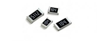
Table of SMD resistor codes and their values
| Code smd | Meaning | Code smd | Meaning | Code smd | Meaning | Code smd | Meaning |
| R10 | 0.1 Ohm | 1R0 | 1 ohm | 100 | 10 ohm | 101 | 100 Ohm |
| R11 | 0.11 Ohm | 1R1 | 1.1 Ohm | 110 | 11 ohm | 111 | 110 Ohm |
| R12 | 0.12 Ohm | 1R2 | 1.2 Ohm | 120 | 12 ohm | 121 | 120 Ohm |
| R13 | 0.13 Ohm | 1R3 | 1.3 Ohm | 130 | 13 ohm | 131 | 130 Ohm |
| R15 | 0.15 Ohm | 1R5 | 1.5 Ohm | 150 | 15 ohm | 151 | 150 Ohm |
| R16 | 0.16 Ohm | 1R6 | 1.6 Ohm | 160 | 16 ohm | 161 | 160 Ohm |
| R18 | 0.18 Ohm | 1R8 | 1.8 Ohm | 180 | 18 ohm | 181 | 180 Ohm |
| R20 | 0.2 Ohm | 2R0 | 2 ohm | 200 | 20 ohm | 201 | 200 Ohm |
| R22 | 0.22 Ohm | 2R2 | 2.2 Ohm | 220 | 22 Ohm | 221 | 220 Ohm |
| R24 | 0.24 Ohm | 2R4 | 2.4 Ohm | 240 | 24 ohm | 241 | 240 Ohm |
| R27 | 0.27 Ohm | 2R7 | 2.7 Ohm | 270 | 27 Ohm | 271 | 270 Ohm |
| R30 | 0.3 ohm | 3R0 | 3 ohm | 300 | 30 ohm | 301 | 300 Ohm |
| R33 | 0.33 Ohm | 3R3 | 3.3 Ohm | 330 | 33 Ohm | 331 | 330 Ohm |
| R36 | 0.36 Ohm | 3R6 | 3.6 Ohm | 360 | 36 Ohm | 361 | 360 Ohm |
| R39 | 0.39 Ohm | 3R9 | 3.9 Ohm | 390 | 39 Ohm | 391 | 390 Ohm |
| R43 | 0.43 Ohm | 4R3 | 4.3 Ohm | 430 | 43 Ohm | 431 | 430 Ohm |
| R47 | 0.47 Ohm | 4R7 | 4.7 Ohm | 470 | 47 Ohm | 471 | 470 Ohm |
| R51 | 0.51 Ohm | 5R1 | 5.1 Ohm | 510 | 51 Ohm | 511 | 510 Ohm |
| R56 | 0.56 Ohm | 5R6 | 5.6 Ohm | 560 | 56 Ohm | 561 | 560 Ohm |
| R62 | 0.62 Ohm | 6R2 | 6.2 Ohm | 620 | 62 Ohm | 621 | 620 Ohm |
| R68 | 0.68 Ohm | 6R8 | 6.8 Ohm | 680 | 68 Ohm | 681 | 680 Ohm |
| R75 | 0.75 Ohm | 7R5 | 7.5 Ohm | 750 | 75 Ohm | 751 | 750 Ohm |
| R82 | 0.82 Ohm | 8R2 | 8.2 Ohm | 820 | 82 Ohm | 821 | 820 Ohm |
| R91 | 0.91 Ohm | 9R1 | 9.1 Ohm | 910 | 91 Ohm | 911 | 910 Ohm |
| Code smd | Meaning | Code smd | Meaning | Code smd | Meaning | Code smd | Meaning |
| 102 | 1 kOhm | 103 | 10 kOhm | 104 | 100 kOhm | 105 | 1 MOhm |
| 112 | 1.1 kOhm | 113 | 11 kOhm | 114 | 110 kOhm | 115 | 1.1 MOhm |
| 122 | 1.2 kOhm | 123 | 12 kOhm | 124 | 120 kOhm | 125 | 1.2 MOhm |
| 132 | 1.3 kOhm | 133 | 13 kOhm | 134 | 130 kOhm | 135 | 1.3 MOhm |
| 152 | 1.5 kOhm | 153 | 15 kOhm | 154 | 150 kOhm | 155 | 1.5 MOhm |
| 162 | 1.6 kOhm | 163 | 16 kOhm | 164 | 160 kOhm | 165 | 1.6 MOhm |
| 182 | 1.8 kOhm | 183 | 18 kOhm | 184 | 180 kOhm | 185 | 1.8 MOhm |
| 202 | 2 kOhm | 203 | 20 kOhm | 204 | 200 kOhm | 205 | 2 MOhm |
| 222 | 2.2 kOhm | 223 | 22 kOhm | 224 | 220 kOhm | 225 | 2.2 MOhm |
| 242 | 2.4 kOhm | 243 | 24 kOhm | 244 | 240 kOhm | 245 | 2.4 MOhm |
| 272 | 2.7 kOhm | 273 | 27 kOhm | 274 | 270 kOhm | 275 | 2.7 MOhm |
| 302 | 3 kOhm | 303 | 30 kOhm | 304 | 300 kOhm | 305 | 3 MOhm |
| 332 | 3.3 kOhm | 333 | 33 kOhm | 334 | 330 kOhm | 335 | 3.3 MOhm |
| 362 | 3.6 kOhm | 363 | 36 kOhm | 364 | 360 kOhm | 365 | 3.6 MOhm |
| 392 | 3.9 kOhm | 393 | 39 kOhm | 394 | 390 kOhm | 395 | 3.9 MOhm |
| 432 | 4.3 kOhm | 433 | 43 kOhm | 434 | 430 kOhm | 435 | 4.3 MOhm |
| 472 | 4.7 kOhm | 473 | 47 kOhm | 474 | 470 kOhm | 475 | 4.7 MOhm |
| 512 | 5.1 kOhm | 513 | 51 kOhm | 514 | 510 kOhm | 515 | 5.1 MOhm |
| 562 | 5.6 kOhm | 563 | 56 kOhm | 564 | 560 kOhm | 565 | 5.6 MOhm |
| 622 | 6.2 kOhm | 623 | 62 kOhm | 624 | 620 kOhm | 625 | 6.2 MOhm |
| 682 | 6.8 kOhm | 683 | 68 kOhm | 684 | 680 kOhm | 685 | 6.8 MOhm |
| 752 | 7.5 kOhm | 753 | 75 kOhm | 754 | 750 kOhm | 755 | 7.5 MOhm |
| 822 | 8.2 kOhm | 823 | 82 kOhm | 824 | 820 kOhm | 815 | 8.2 MOhm |
| 912 | 9.1 kOhm | 913 | 91 kOhm | 914 | 910 kOhm | 915 | 9.1 MOhm |
Code marking
encodes the value of resistors in accordance with generally accepted standards, i.e. the first two or three digits indicate the ohm rating, and the last - the number of zeros (multiplier). Depending on the accuracy of the resistor, the value is encoded as 3 or 4 characters. Differences from the standard encoding may lie in the interpretation of the numbers 7, 8 and 9 in the last character.
The letter R acts as a decimal point or, when it comes at the end, it indicates a range. A single "0" indicates a Zero-Ohm resistor.
Code marking
| Last character | Resistor value |
| 1 | 100…976 Ohm |
| 2 | 1…9.76 kOhm |
| 3 | 10…97.6 kOhm |
| 4 | 100…976 kOhm |
| 5 | 1…9.76 MOhm |
| 6 | 10…68 MOhm |
| 7 | 0.1…0.976 Ohm |
| 8 | 1…9.76 Ohm |
| 9 | 10…97.6 Ohm |
| 0 | 0 ohm |
| R | 1…91 Ohm |
Thus, if you see code 107 on the resistor, this is not 10 followed by seven zeros (100 MOhm), but only 0.1 Ohm.
Design and principle of operation
The design of a variable non-wire resistor is shown in the figure. A conductive layer 2 is applied to the insulating base 1. A protective layer 3 is applied on top. A contact unit 4 moves along the protective layer. The ends of the conductive layer are equipped with current collecting pads 5.
1 - insulating base; 2 - conductive layer; 3 - protective layer; 4 - contact unit; 5 - current collecting platforms.
One potentiometer can consist of several resistive elements and contact units. Such potentiometers are called dual potentiometers. This type has found application in audio technology to control the volume of several channels.
With dual potentiometers, one shaft moves two independent contact units.
Some potentiometers have a limit switch in the initial position. Such potentiometers are equipped with two additional terminals.
Changing the resistance can be carried out not only by manually moving the contact assembly, but also by using external signals. These potentiometers include digital potentiometers. They are a microcircuit. A resistive matrix is placed inside; the resistance is changed by switching transistor switches. Control can be carried out by discrete signals (more, less), via a parallel or serial bus.
The load is connected to terminals A, B, W.
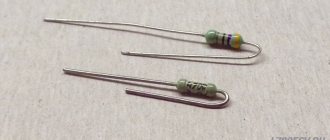
Jumpers and resistors with “zero” resistance
Many companies produce special Jumper Wires with standardized resistance and diameter (0.6 mm, 0.8 mm) and resistors with “zero” resistance as fuse links or jumpers. Resistors are available in a standard cylindrical package with flexible leads (Zero-Ohm) or in a standard surface mount package (Jumper Chip). The actual resistance values of such resistors are in the range of units or tens of milliohms (~ 0.005...0.05 Ohm). In cylindrical housings, the marking is carried out with a black ring in the middle; in surface-mount housings (0603, 0805, 1206...) there is usually no marking or the code “000” (possibly “0”) is applied.
Jumpers and resistors with zero resistance.
Purpose
Resistors are a passive element of an electrical circuit that does not convert energy from one type to another. They have active resistance. Their main characteristic is nominal resistance. No less important is a characteristic such as power.
Variable resistors can change their resistance using an accessible adjuster. Act as a current or voltage regulator.
Trimmer resistors have a control that changes the resistance, but it is not available for manual adjustment. To do this you need to use a special screwdriver. These resistors are used only for setting the operating modes of a technical device and are not intended for frequent use.
Non-standard color marking
In addition to standard color markings, many companies use non-standard (in-house) markings. Non-standard markings are used to distinguish, for example, resistors manufactured according to MIL standards from industrial and household standards, indicate fire resistance, etc.
Non-standard color marking.
Application area
Trimmer variable resistors are widely used in electronic and electrical devices. They are used to adjust the current value in circuits and as voltage dividers. At low frequencies up to 1 megahertz, no problems are observed with their use.
When operating at high frequencies, the resistors’ own inductance and capacitance begin to affect; this factor must be taken into account. When selecting parts, you should pay attention to the operating frequency range. It is not recommended to work with the maximum permissible resistor parameters.
Code marking
A. 3-digit marking
The first two digits indicate the values in Ohms, the last - the number of zeros. Applies to resistors from the E-24 series, with tolerances of 1 and 5%, sizes 0603, 0805 and 1206.
B. 4-digit marking
The first three digits indicate the values in Ohms, the last - the number of zeros. Applies to resistors from the E-96 series, with a tolerance of 1%, sizes 0805 and 1206. The letter R acts as a decimal point.
C. 3-character marking
The first two characters are numbers indicating the resistance value in Ohms, taken from Table 5 below, the last character is a letter indicating the value of the multiplier: S = 10-2; R=10-1; A=1; B= 10; C=102; D=103; E=104; F=105. Applies to resistors from the E-96 series, with a tolerance of 1%. size 0603.
| Code | Meaning | Code | Meaning | Code | Meaning | Code | Meaning |
| 01 | 100 | 25 | 178 | 49 | 316 | 73 | 562 |
| 02 | 102 | 26 | 182 | 50 | 324 | 74 | 576 |
| 03 | 105 | 27 | 187 | 51 | 332 | 75 | 590 |
| 04 | 107 | 28 | 191 | 52 | 340 | 76 | 604 |
| 05 | 110 | 29 | 196 | 53 | 348 | 77 | 619 |
| 06 | 113 | 30 | 200 | 54 | 357 | 78 | 634 |
| 07 | 115 | 31 | 205 | 55 | 365 | 79 | 649 |
| 08 | 118 | 32 | 210 | 56 | 374 | 80 | 665 |
| 09 | 121 | 33 | 215 | 57 | 383 | 81 | 681 |
| 10 | 124 | 34 | 221 | 58 | 392 | 82 | 698 |
| 11 | 127 | 35 | 226 | 59 | 402 | 83 | 715 |
| 12 | 130 | 36 | 232 | 60 | 412 | 84 | 732 |
| 13 | 133 | 37 | 237 | 61 | 422 | 85 | 750 |
| 14 | 137 | 38 | 243 | 62 | 432 | 86 | 768 |
| 15 | 140 | 39 | 249 | 63 | 442 | 87 | 787 |
| 16 | 143 | 40 | 255 | 64 | 453 | 88 | 806 |
| 17 | 147 | 41 | 261 | 65 | 464 | 89 | 825 |
| 18 | 150 | 42 | 267 | 66 | 475 | 90 | 845 |
| 19 | 154 | 43 | 274 | 67 | 487 | 91 | 866 |
| 20 | 158 | 44 | 280 | 68 | 499 | 92 | 887 |
| 21 | 162 | 45 | 287 | 69 | 511 | 93 | 909 |
| 22 | 165 | 46 | 294 | 70 | 523 | 94 | 931 |
| 23 | 169 | 47 | 301 | 71 | 536 | 95 | 953 |
| 24 | 174 | 48 | 309 | 72 | 549 | 96 | 976 |
Note. Markings A and B are standard, marking C is in-house.
Potentiometers
The potentiometer differs from other types of resistance in that it has three terminals:
- 2 permanent, or extreme;
- 1 movable, or middle.
The first two terminals are located at the edges of the resistive element and are connected to its ends. The middle output is combined with a movable slider, through which movement occurs along the resistive part. Due to this movement, the resistance value at the ends of the resistive element changes.
All variants of variable resistors are divided into wire and non-wire, this depends on the design of the element.
How does a resistor work?
To create a non-wire variable resistor, rectangular or horseshoe-shaped plates from insulate are used, on the surface of which a special layer is applied that has a given resistance. Typically the layer is a carbon film. Less commonly used in design:
- microcomposite layers of metals, their oxides and dielectrics;
- heterogeneous systems of several elements, including 1 conductive element;
- semiconductor materials.
Attention! When using resistors with carbon film in the power circuit, it is important to prevent the element from overheating, otherwise sudden voltage drops may occur during the adjustment process.
When using a horseshoe-shaped element, the slider moves in a circle with a rotation angle of up to 2700C. Such potentiometers have a round shape. The rectangular resistive element has a translational slider movement, and the potentiometer is made in the form of a prism.
Wire options are built on the basis of high-resistance wire. This wire is wound around a ring-shaped contact. During operation, the contact moves along this ring. In order to ensure a strong connection to the contact, the track is additionally polished.
What does a wire-wound variable resistor look like?
The material used depends on the accuracy of the potentiometer. Of particular importance is the diameter of the wire, which is selected based on the current density. The wire must have high resistivity. In production, nichrome, manganin, constatin and special alloys of noble metals, which have low oxidation and increased wear resistance, are used for winding.
In high-precision instruments, ready-made rings are used where the winding is placed. For such winding, special high-precision equipment is required. The frame is made of ceramics, metal or plastic.
If the accuracy of the device is 10-15 percent, then a plate is used, it is rolled into a ring after winding. Aluminum, brass or insulating materials, for example, fiberglass, textolin, getinax, are used as a frame.
Note! The first sign of resistor failure may be a crackling or noise when turning the knob to adjust the volume. This defect occurs as a result of wear of the resistive layer, and, therefore, loose contact.
Marking of variable resistors
Imported
The complete marking of variables and trimmer resistors is an alphanumeric code:
1. Series.
2. Functional characteristic (Fig. 1.6) - a graph of resistance versus engine rotation.
3. Resistance value in ohms (2K2 = 2.2 kOhm).
4. Type of engine (Fig. 1.7, Table 1.16).
5. Length of the engine in mm.
Rice. 1.6. Graph of resistance depending on the angle of rotation of the variable resistor motor
Table 1.16
| Type | Designation | Dimensions, mm | ||||
| KS | L | 15 | 20 | 25 | 30 | 35 |
| IN | 7 | 12 | 14 | 14 | 14 | |
| F | L | 15 | 20 | 25 | 30 | 35 |
| F | 8 | 12 | 12 | 12 | 12 | |
| RE | L | 15 | 20 | 25 | 30 | 35 |
| R | L | 15 | 20 | 25 | 30 | 35 |
| KQ | L | 15 | 20 | 25 | 30 | 35 |
| A | 6 | 7 | 7 | 7 | 7 |
Rice. 1.7. Types of variable resistor motors
Separately, it is recommended to highlight tuning resistors from Murata, used in microelectronics. They are designated according to the internal company system. The marking consists of a model code - three letters and a number, a type - 1-2 letters and a denomination indicated by a digital code. for example, RVG3 A8–103. In Fig. 1.8 shows images of trimming resistors from Murata.
Rice. 1.8. Trimmer resistors from Murata
Source
Domestic
Abbreviations for resistors consist of letters and numbers. The letters indicate a group of products: C - constant resistors (the letter “C” remains from the old name for resistors - “resistance”), SP - variable resistors. The number after the letters indicates a specific type of resistor depending on the material of the conductive element: 1 - non-wire thin-layer carbon and boron carbon; 2 - non-wire thin-layer metal-dielectric and metal-oxide; 3 - non-wire composite films; 4 - non-wire composite volumetric; 5 - wire; 6 - non-wire thin-layer metallized.
After the first digit, a second digit is placed through defns, indicating the registration number of a specific type of resistor.
For example, SP5-24 designates variable wire resistors, registration number 24
In our country and the CMEA countries, a new system of abbreviated designations has been adopted for newly developed resistors, according to which the first element, a letter, denotes the subclass of the resistor (P - constant resistors, RP - variable resistors), the second element - a number, denotes the resistor group according to the resistive material element (1—non-wire, 2—wire), the third element is a number, indicating the registration number of the resistor. A hyphen is placed between the second and third elements. For example, RP1-46 denotes non-wire variable resistors, registration number 46.
When ordering resistors and their delivery, the full designation is indicated in the documents. It consists of an abbreviated designation, design option (if necessary), designation and the values of the main parameters and characteristics of the resistors, climatic design and designation of the delivery document.
The parameters and characteristics for variable resistors are named in the following sequence: rated power dissipation and power units (W), nominal resistance and resistance units (Ohm, kOhm, MOhm), permissible resistance deviation in % (tolerance), functional characteristic (for non-wire resistors), designation of the end of the shaft and the length of the protruding part of the shaft (VS-1 - solid smooth, VS-2 - solid with a slot, VS-3 - solid with a flat, VS-4 - solid with two flats, VP-1 - hollow smooth , VP 2 - hollow with a flat).
The marking is applied directly to the resistor and contains: type, rated power, rated resistance, tolerance and date of manufacture. For non-wire variable resistors, the type of functional dependence A, B, C, etc. is also indicated. When marking nominal resistances and their permissible deviations, both full and abbreviated (coded) designations can be used. The full designation of nominal resistance consists of the value of the nominal resistance (digit) and the unit of measurement (Ohm, kOhm, MOhm).
The coded designation consists of two or three numbers and letters. The letter of the code from the Russian alphabet indicates the multiplier that makes up the resistance value and determines the position of the decimal point. The letters E, K, M indicate, respectively, the multipliers 1, 10, 100 for resistance values expressed in ohms. The values of permissible deviations are also coded with the letters ±5% - I, ±10% - C, ±20% - B, ±30% - F.
Examples of coded designations 6E8I, 1K5V, 2M2F - means 6.8 Ohm±5%, 1.5 k0m±20%, 2.2 M0m±30%.
Source
Adjustment resistors can also differ in the dependence of the resistance itself on the angle of rotation of the axis of their engine.
Let's look at the picture.
By and large, adjustment resistors can be divided into three types:
A - with a linear dependence, B - with a logarithmic one and C - with an exponential one. (Figure left). Volume controls, as a rule, use resistors with an exponential dependence “ B ”, this is due to the peculiarities of human hearing.
Classification
Classification by materials
According to the material of the resistive element, variable resistors are divided into:
- wire - the resistive element is a wire wound on a dielectric frame;
- non-wire - the resistive element is a film of material (metal or a composition of several materials).
Classification according to the trajectory of movement of the contact unit
Depending on the trajectory of movement of the contact assembly, potentiometers are divided into:
- slider (slide potentiometers) – the contact unit moves linearly. The resistive element is a straight strip.
- rotary (rotary potentiometers) - the contact unit moves around a circle. The resistive element is an arc (horseshoe).
Depending on the angle of rotation, rotary potentiometers are divided into:
- single-turn;
- multi-turn.
The trajectory of movement of the control body may not coincide with the trajectory of the contact unit. For example, when using a screw-nut type transmission.
Features of trimming resistors
Resistor
Such radio components are necessary to configure equipment elements during repair, adjustment or assembly. The main difference between trimming resistors and other models is the existence of an additional locking element. The operation of these resistors uses a linear relationship.
Flat and ring resistive elements are used to create components. If we are talking about using devices under heavy loads, then cylindrical structures are used. In the diagram, instead of an arrow, a tuning adjustment sign is placed.