Good day. When laying wiring in a private house, how to properly ground?
In order to leave your answer to a question, you must log in or go through a quick registration procedure Register!
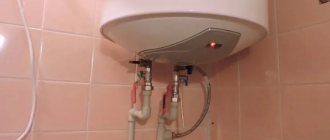
In a modern private home there are many electrical appliances that need to be grounded to ensure their safe use.
The cross-section of the wire for grounding in a private house is selected depending on its operating conditions. The Electricity Supply Rules (PUE) state that any power-consuming device with a voltage of 220V must be connected to the electrical network with a cable of three wires. The third wire is the neutral ground wire or ground wire. With an existing 380V network, a four-wire cable must be used for power supply.
Properly performed grounding should be a closed loop. The grounding loop is connected to the PE bus using a copper wire. The cross-section of the wire for grounding in a private house, when using insulated wires of a single-phase network, must be at least 2.5 mm2. In this case, you need to know that the cross-section of the grounding wire is always smaller than the cross-section of the wires through which the current passes.
When using a non-insulated phase input into a house made of copper wire with a cross-section of 6 mm2, stranded copper wires of the same cross-section are used for grounding.
If the power distribution panel, when entering the building, is made correctly, it should contain phase wires and a “neutral”, and a PE grounding bus should be present. The grounding wires of electrical appliances are connected to it. The PE bus is connected to the ground loop of the entire building. The grounding loop includes the following elements: electric current consumers, a distribution panel, with a PE grounding bus, a grounding conductor and a grounding conductor.
Grounding conductors can be existing suitable elements; in their absence, artificial grounding conductors can be made. They can be used as steel reinforcement with a diameter of at least 16 mm or a steel angle with a side of 50 mm. These are vertical grounding conductors; they are driven into the ground. To obtain a closed loop, vertical grounding conductors must be linked with horizontal connections. To do this, use metal corners or wire. They are connected by welding or bolts. The connection must be continuous. The resulting circuit is connected to a grounding bus and a grounding conductor.
After creating a grounding loop, you need to measure its resistance and compare its value with the permissible standards of PUE and PTEEP.
Modern household appliances and equipment require grounding. Only in this case will manufacturers maintain their guarantees. Residents of apartments have to wait for the networks to be overhauled, while home owners can do everything themselves. How to make grounding in a private house, what is the procedure and connection diagrams - read about all this here.
Types of ground loops
In general, ground loops can be in the form of a triangle, rectangle, oval, line or arc. The best option for a private home is a triangle, but others are also quite suitable.
Grounding in a private house - types of grounding loops
Triangle
Grounding in a private house or country house is most often done with a contour in the form of an isosceles triangle. Why is that? Because with such a structure, in a minimum area we obtain a maximum area for current dissipation. The costs of installing a grounding loop are minimal, and the parameters correspond to the standards.
Most often, grounding in a private house is done with a triangle-shaped circuit
The minimum distance between the pins in the ground loop triangle is their length, the maximum is twice the length. For example, if you drive the pins to a depth of 2.5 meters, then the distance between them should be 2.5-5.0 m. In this case, when measuring the resistance of the ground loop, you will get normal values.
During work, it is not always possible to make the triangle strictly isosceles - stones come across in the right place or other difficult-to-pass areas of soil. In this case, you can move the pins.
Linear ground loop
In some cases, it is easier to make a ground loop in the form of a semicircle or a chain of pins lined up (if there is no free area of suitable dimensions). In this case, the distance between the pins is also equal to or greater than the length of the electrodes themselves.
With a linear circuit, a larger number of vertical electrodes is necessary so that the dissipation area is sufficient
The disadvantage of this method is that to obtain the required parameters, a larger number of vertical electrodes is required. Since hammering them in is still a pleasure, if there is a meta, they try to make a triangular outline.
Useful tips
In connection with grounding a house with their own hands, private home owners and new developers often encounter some problems that they cannot solve themselves. For example, do-it-yourself grounding in a private house (380V supply voltage). Are there any special features during installation? There are no special features, because the three-phase connection inside the house is divided into single-phase circuits, which are evenly scattered throughout the building. For example, one phase goes to lighting, the second to sockets, the third is connected, for example, to a boiler. The house has to be grounded using one circuit. That is, the ground wire coming out of the house is connected to the bus where the ground electrode from the street was connected. At the same time, indoors, the grounding loop connects all sockets and powerful household appliances to each other, as separate consumers.
Is it possible to ground a house using a basement or cellar? There are no problems here either. The main thing is that the grounding in the basement (cellar) is completely in the ground so that the resistance of the structure is minimal. In this case, the cellar will be an ideal place (wet floor and soil that conduct current well), the only requirement for it is to cover the installation site of the circuit with protective devices, for example, lay wooden grates on the floor.
Ground loop materials
For the grounding of a private house to be effective, its resistance should not be more than 4 ohms. To do this, it is necessary to ensure good contact of the grounding conductors with the ground. The problem is that grounding resistance can only be measured with a special device. This procedure is carried out when putting the system into operation. If the parameters are worse, the act is not signed. Therefore, when doing the grounding of a private house or cottage with your own hands, try to strictly adhere to the technology.
Example of grounding for a private house
Pin parameters and materials
Grounding pins are usually made of ferrous metal. Most often, a rod with a cross-section of 16 mm or larger or a corner with parameters 50 * 50 * 5 mm (5 cm shelf, metal thickness - 5 mm) is used. Please note that reinforcement cannot be used - its surface is hardened, which changes the distribution of currents, and in addition, in the ground it quickly rusts and collapses. What is needed is a rod, not reinforcement.
Read also: Inverter motor operating principle
Possible electrode profiles
Another option for arid regions is thick-walled metal pipes. Their lower part is flattened into a cone, and holes are drilled in the lower third. To install them, holes of the required length are drilled, since they cannot be driven in. When soils dry out and grounding parameters deteriorate, a saline solution is poured into the pipes to restore the dissipative capacity of the soil.
The length of the grounding rods is 2.5-3 meters. This is sufficient for most regions. More specifically there are two requirements:
- the grounding loop rod must extend into the ground below the freezing level by at least 60 cm (preferably 80-100 cm);
- in arid regions, at least 1/3 of the ground electrode should be in wet soils, so you also need to focus on the level of groundwater - if it is low, longer rods may be needed.
The most commonly used steel angle and strip
Specific grounding parameters can be calculated, but the results of a geological study are required. If you have any, you can order a calculation from a specialized organization.
What to make metal connections from and how to connect them with pins
All pins of the circuit are connected to each other by metal bonding. It can be made from:
- copper wire with a cross section of less than 10 mm 2;
- aluminum wire with a cross-section of at least 16 mm 2
- steel conductor with a cross section of at least 100 mm 2 (usually a strip of 25 * 5 mm).
Most often, the pins are connected to each other using a steel strip. It is welded to the corners or heads of the rod. It is very important that the quality of the weld is high - this determines whether your grounding will pass the test or not (whether it will meet the requirements - resistance less than 4 ohms).
Parameters that must be achieved when making a ground loop yourself
When using aluminum or copper wire, a large cross-section bolt is welded to the pins, and the wires are already attached to it. The wire can be screwed onto a bolt and pressed with a washer and nut, or the wire can be terminated with a connector of a suitable size. The main task is the same - to ensure good contact. Therefore, do not forget to strip the bolt and wire to bare metal (can be treated with sandpaper) and tighten well - for good contact.
What are electrical cables made of?
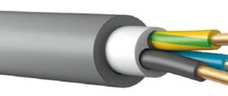
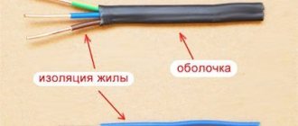
The main elements of any electrical cable are the cores - elements for the passage of electric current, isolated from each other by an internal sheath and enclosed in a common sheath. They are designated by the abbreviation TPG.
In addition to current-carrying cores (1), the cable may contain such structural elements as core (3), wire or steel armor (2) and outer sheath (4)
There are two types of conductors for transmitting electrical energy:
- single-wire solid;
- stranded, consisting of a large number of thin threads.
Some people mistakenly believe that single-wire conductors and single-core cables are an identical concept. In fact, single-core products can have only one core, which, in turn, can be made of single or multi-wire.
The basis for the manufacture of current-carrying conductors can be copper or aluminum. If we compare these metals, then aluminum, although it is cheaper, loses in that it has a lower level of electrical conductivity.
This means that with an equal cross-section, a copper conductor is capable of passing more current. The only “minus” of copper is that it quickly deteriorates in air.
Aluminum is not the best option for wiring in the house, since it has a low level of electrical conductivity, and during operation it oxidizes faster and breaks at bends.
When working with these materials, it is worth considering that aluminum and copper form a galvanic couple. This connection quickly breaks down. Therefore, they can only be connected to each other by installing a terminal block.
If the connection is made by twisting, then this place will quickly oxidize, which will lead to a break in the contacts, which may result in a short circuit in the line. Ideally, you should choose the same type of wire for all lines in the apartment.
Cables for electrical signals are equipped with a sheath. The insulating layer can be made of:
- rubber;
- polyethylene;
- PVC plastic.
Each of these materials is characterized by high electrical characteristics. Thanks to this, they can be used in networks of various voltage classes within 500 W.
The main purpose of the outer braid is to protect conductors from moisture, which can lead to damage to the integrity of the insulation and, as a result, to clouding of optical fibers
Any cable used for intra-house and apartment wiring has at least two insulating layers: the first protects the internal cores collected in a bundle, the second encircles only one core.
How to make grounding yourself
After all materials have been purchased, you can begin the actual manufacture of the ground loop. First, cut the metal into pieces. Their length should be about 20-30 cm longer than the calculated one - when driven in, the tops of the pins bend, so you have to cut them off.
Sharpen the clogged edges of the vertical electrodes - things will go faster
There is a way to reduce the resistance when driving electrodes - sharpen one end of the angle or pin at an angle of 30°. This angle is optimal when driving into the ground. The second point is to weld a metal pad to the upper edge of the electrode, from above. Firstly, it is easier to hit, and secondly, the metal is less deformed.
Work order
Regardless of the shape of the contour, it all starts with excavation work. It is necessary to dig a ditch. It is better to make it with beveled edges - this way it crumbles less. The order of work is as follows:
- The area where the grounding loop will be placed is cleared and markings are applied.
- According to the markings, they dig a trench 70-80 cm deep and about 50 cm wide. The depth is not accidental - if you lay the metal connection lower or higher, the metal will corrode faster.
- The prepared pins are placed in the designated places and hammered until a section of about 20 cm remains above the surface.
The process of manufacturing a grounding loop - for grounding in a private house
Only the weld areas need to be painted.
Ground loop diagram with dimensions
Actually, that's all. We did the grounding in a private house with our own hands. All that remains is to connect it. To do this, you need to understand the grounding organization diagrams.
Inserting a ground loop into the house
The ground loop must somehow be connected to the ground bus. This can be done using a steel strip of 24 * 4 mm, copper wire with a cross-section of 10 mm2, and aluminum wire with a cross-section of 16 mm2.
If wires are used, it is better to look for them in insulation. Then a bolt is welded to the circuit, and a sleeve with a contact pad (round) is put on the end of the conductor. A nut is screwed onto the bolt, a washer is screwed onto it, then a wire, another washer is placed on top, and the whole thing is tightened with a nut (picture on the right).
How to bring “earth” into the house
When using a steel strip, there are two options - bring a tire or wire into the house. I really don’t want to pull a steel tire measuring 24*4 mm - it looks unaesthetic. If there is, you can use the same bolted connection to install a copper busbar. It needs a much smaller size, it looks better (photo on the left).
You can also make a transition from a metal bus to a copper wire (cross section 10 mm2). In this case, two bolts are welded to the tire at a distance of several centimeters from each other (5-10 cm). The copper wire is twisted around both bolts, pressing them with a washer and nut to the metal (tighten as best as possible). This method is the most economical and convenient. It doesn't require as much money as using only copper/aluminum wire, and it's easier to run it through the wall than a busbar (even a copper one).
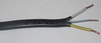
PuGV-HL cable
The PuGV-HL cable is used for connecting lighting networks and installing electrical appliances with an alternating voltage of 450 V and a frequency of 400 Hz. Suitable for single installation in cable buildings and industrial premises.
Determining the place
First we need to find a place where we will make a grounding loop. The safety of using the circuit will depend on this choice. The location is chosen taking into account the fact that no one will be there.
Ground work
Once we have decided on the location, we begin the excavation work. Dig a trench shaped like a triangle with a shovel. The distance between the corners should preferably be 1.2 m, the length of the sides should be 3 m, and the depth should be 50 - 80 cm. The next trench is dug towards the porch of the house, of the same depth. Then, using an earth drill, holes are made at the corners of the triangle.
Assembly of the structure
Using a grinding machine, the ends of the steel angles are sharpened. Then they are driven into the prepared holes with a sledgehammer to a depth of more than two meters. Leave 20 cm at the top for horizontal installation. After this, steel plates are welded to the hammered in corners to form a metal triangular frame.
The next step is to weld one end of the bolt plate. The plate is placed in a trench that leads from the house and welded at the other end to one of the closest corners of the triangular structure. The places where the welding was performed are treated with a special anti-corrosion compound, and then the holes are filled with earth.
The length of the copper power cable (PuGV or VVGNG) is measured and cut. Its ends are cleaned. One end of the cable is connected to the electrical panel, and the other to the ground plate bolt.
Grounding schemes: which one is better to make?
Currently, in the private sector, only two grounding connection schemes are used - TN-CS and TT. For the most part, a two-core (220 V) or four-core (380 V) cable (TN-C system) is suitable for the house. With such wiring, in addition to the phase (phase) wire, there is a protective conductor PEN, in which neutral and ground are combined. At the moment, this method does not provide adequate protection against electric shock, so it is recommended to replace the old two-wire wiring with a three-wire (220 V) or five-wire (380 V).
Read also: Do-it-yourself gas generator for 220 volts
Two schemes that are used if you need to make grounding in a private house
In order to obtain normal three- or five-wire wiring, it is necessary to separate this conductor into ground PE and neutral N (in this case, an individual ground loop is required). This is done in the entrance cabinet on the facade of the house or in the accounting and distribution cabinet inside the house, but always before the meter. Depending on the separation method, either a TN-CS or TT system is obtained.
Installation of a TN-CS grounding system in a private house
When using this circuit, it is very important to make a good individual ground loop. Please note that with the TN-CS system, protection against electric shock requires the installation of RCDs and breakers. Without them there is no talk of any protection.
Also, to ensure protection, it is necessary to connect all systems that are made of conductive materials - heating, water supply, foundation reinforcement frame, sewerage, gas pipeline (if they are made of metal pipes) to the earth bus with separate wires (inextricable). Therefore, the grounding bus must be taken “with a reserve”.
Scheme for converting the TN-C system to TN-C-S
To separate the PEN conductor and create grounding in a private house TN-CS, three buses are needed: on a metal base - this will be a PE (ground) bus, and on a dielectric base - this will be an N (neutral) bus, and a small splitter bus for four " seating places.
The metal “ground” bus must be attached to the metal body of the cabinet so that there is good electrical contact. To do this, at the fastening points, under the bolts, the paint is removed from the body to bare metal. The zero bus - on a dielectric base - is best mounted on a DIN rail. This installation method fulfills the basic requirement - after separation, the PE and N buses should not intersect anywhere (should not have contact).
Grounding in a private house - transition from the TN-C system to TN-C-S
Next we connect like this:
- The PEN conductor coming from the line is connected to the bus splitter.
- We connect the wire from the ground loop to the same bus.
- From one socket with a copper wire with a cross-section of 10 mm 2 we place a jumper on the ground bus;
- From the last free socket we place a jumper on the zero bus or neutral bus (also a 10 mm 2 copper wire).
Now that's it - grounding in a private house is done according to the TN-CS scheme. Next, to connect consumers, we take the phase from the input cable, zero from the N bus, and ground from the PE bus. We make sure that ground and zero do not intersect anywhere.
Grounding according to the TT system
Converting a TN-C circuit to TT is generally simple. There are two wires coming from the pole. The phase conductor is further used as a phase, and the protective PEN conductor is attached to the “zero” bus and is then considered zero. The conductor from the made circuit is directly supplied to the grounding bus.
Do-it-yourself grounding in a private house - TT diagram
The disadvantage of this system is that it provides protection only for equipment that requires the use of an “earth” wire. If there are also household appliances made using a two-wire circuit, they may be energized. Even if the housings are grounded with separate conductors, in case of problems, the voltage may remain at “zero” (the phase will be broken by the machine). Therefore, of these two schemes, TN-CS is preferred as it is more reliable.
Grounding is the intentional contact of any point in the electrical network or equipment with a ground loop. Grounding ensures lightning protection and safe use of electrical household appliances. When carrying out wiring repairs, inexperienced technicians often do not know what color the grounding wire in the electrical wiring should be. Information about the color of wires is not difficult to understand, but it is necessary to know it in order to carry out electrical installation work safely and efficiently.
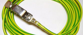
Why do you need a grounding wire, how it works
Connecting a ground wire to a bus
The main purpose of grounding is to prevent electric shock to a person or animal. A serviceable electrical device has a complete body with reliably insulated parts that are energized. If a household appliance breaks down, live parts may touch the housing and this will lead to the fact that it will also be energized. By touching such a device, a person will inevitably receive an electric shock.
In this case, the operation of a circuit breaker is impractical, since the current flowing through the human body will not be enough to turn off the power supply. But this force, unfortunately, is enough to deprive a person of health or even life.
To eliminate the possibility of such events, you need to ground all electrical devices through conductors. Grounding household appliances at home is only possible if the house is equipped with a ground loop. Unfortunately, houses in older buildings are not equipped with such innovations. This is due to the fact that decades ago people had practically no household appliances in their homes, therefore, the load on the network was minimal.
Now another conductor is added to the two-phase wiring - a grounding wire. As a result, the wiring is already three-phase - two wires are zero and phase, and the third is protective grounding. Thus, when connecting the plug of a household appliance to a socket, the metal body of the device is automatically connected to the protective ground.
Purpose
According to the standards of PUE and GOST (18714-81), residential and industrial premises must have a protective grounding system. The grounding device is subject to testing, after which a report on its condition is drawn up.
The principle of operation of the grounding system is most easily explained using an example when a phase wire is damaged and a current leak occurs. In most cases, electrical wiring in a residential building is protected in the form of a residual current device. However, the RCD is effective in the presence of differential current (not always or not immediately available). Such a current manifests itself only when the conductor is connected to a point with a different potential. Since the earth resistance is high, the protective shutdown device is triggered.
However, if, for the reasons stated above, the RCD does not give the desired effect or such a device is absent altogether, then the current is directed to unprotected taps. This is a dangerous situation because it could result in an electric shock to the person who touches the tap.
Marking
Ground wires are designated in two ways:
Ground color
Grounding is usually indicated by the color yellow-green. Pure yellow or light green wires are much less common. The cable may have a blue braid at the ends where it is fixed, which indicates grounding in conjunction with zero.
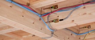
In a switchboard, the grounding is connected to the grounding bus, the housing and the metal door of the switchboard. In the junction box, the connection is routed to the ground wires from the lighting fixtures and the ground contacts of the outlets.
Note! The grounding conductor should not be connected to the residual current device.
The following shows the grounding symbol on electrical circuit diagrams.
- Standard grounding.
- Clean grounding.
- Protective grounding.
- Grounding to the electrical equipment housing.
- Grounding for DC current.
Neutral color
The neutral conductor is indicated in blue. In the distribution board it is connected to the neutral bus, marked with the letter N. All blue conductors are also connected there. The bus is connected to the input through an electric meter or directly, without installing a machine. In the distribution box, all blue wires (except for the wire from the switch) are not involved in switching. In sockets, the neutral conductors are connected to a contact, which is designated by the letter N (located on the back of the socket).
Read also: Drawing of a roller on bearings
Phase color
The color scheme for marking the phase wire is more varied compared to grounding and neutral. Use brown, black, red or any other colors except yellow, green and blue.
In the switchboard, the phase leaving the consumer is connected to the lower contact of the automatic switch or residual current device. Phase switching occurs in switches. After closing the contact, the voltage is directed to consumers. In phase sockets, the black conductor should be connected to the contact marked with the letter L.
Letters in markings
To indicate the types of wires, the following letter designations are used:
- A - the conductor core is made of aluminum. If A is not indicated in the marking, the core is made of copper.
- AA is a stranded conductor with an aluminum core and additional aluminum braiding.
- AC - there is an additional lead braid.
- B - the cable belongs to the moisture-protected category. The braid is made of two-layer steel.
- BN - cable braid is resistant to fire.
- B - the shell is made of polyvinyl chloride.
- G - the shell is not used.
- r - the cable is bare and waterproof.
- K - control cable with wire winding.
- R - a rubber shell is used.
- NP - non-flammable rubber casing.
Independent wire designation
Sometimes there are conductors painted in colors that are unusual for them. Such color schemes do not comply with the standards specified in the Electrical Installation Rules. To make the task of arranging the wiring easier, it is recommended to do your own color marking. For this purpose, colored electrical tape is suitable, which is used to mark the ends of the conductors in the switchboard. Heat-shrinkable tubing is also used for marking. All that remains is to write down in a notepad the meanings of the colors with which this or that wire is marked.
Popular brands
When selecting a cable brand, you should proceed from its type: stationary or mobile use. The stationary version is used to protect buildings, electrical panels and equipment. Multicore stranded cables (PVG, BBG), as well as single-wire modifications (NYM), are suitable for such purposes. Fixed type cables use a green-yellow grounding conductor. If the grounding cable is colorless, the ground is directed to the core.
NYM cable
The NYM brand is used for transporting electricity in stationary conditions. The cable is designed for alternating voltage with a frequency of 50 Hz. It is allowed to connect electrical equipment of the first security class to the conductor.
- copper core;
- the presence of an intermediate shell;
- the color complies with the standard of the Rules for the Operation of Electrical Installations (green-yellow insulation);
- Convenient for electrical installation work.
VVG cable
Products of this type are equipped with copper conductors of the first and second stranding classes. The insulating layer is always polyvinyl chloride. Some cable models are produced as multi-core cables. Three-, four-, five-core cables have a neutral and grounding. The insulation of the core intended for grounding is made of green-yellow polyvinyl chloride plastic.
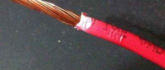
Cable PV-3
Products of this type include one core, which contains twisted copper wires. When painting the shell, different colors are used. For grounding, yellow and green-yellow colors are used.
Cable PV-6
The cable design contains a multi-wire conductor made of copper. The insulating layer is made of transparent polyvinyl chloride plastic. The material is highly resistant to mechanical stress. Thanks to the transparency of the plastic compound, it is easy to monitor the integrity of the product. There are no standards for the color of the PV-6 shell. In connection with this circumstance, it is recommended to independently mark the cable with the desired color before carrying out electrical installation work.
ESUY cable
This type of cable is used to protect networks from short circuits. ESUY is also often used in power systems with significant currents. The cable is temperature resistant, lightweight and highly flexible. There is no voltage rating for ESUY because it is not designed to carry current. When laying the cable, you should take care of its color designation yourself.
Checking the correct marking and wiring
Color schemes in electrical engineering help speed up the identification of wires. However, you should not completely rely on color designations, since a connection error is quite possible. Based on this, it is recommended to check whether the colors match the intended purpose of the wires.
If the wires are not color coded, you will need an indicator. With its help, the phase is found. Where the indicator lights up is the phase. In other cases we are talking about zero and grounding.
If the wire is two-wire, there will be no problems identifying the right wire. However, in the case of a three-core cable, you cannot do without a multimeter. It is fixed in phase, after which the other contact of the conductor is checked. When zero is detected, the device will show 220 volts. For grounding, the indicator will be less than 220.