The protocol for measuring insulation resistance in a single-phase network is filled out by electrical laboratories and other organizations whose activities are related to electrical installation work. It is necessary for drawing up an insulation resistance measurement report and is the basis for filling out its data.
- Form and sample
- Online viewing
- Free download
- Safely
FILES
This document is also part of the technical report on electrical measurements. Electrical engineering companies of various types can thus sum up the results of their work and report to customers or higher authorities on the conduct of relevant research.
Different types of measurements
Protocols for measuring the insulation resistance of single-phase and three-phase circuits look different.
For a single-phase circuit, three measurements are sufficient; for a three-phase circuit there should be ten (if it is five-wire).
For this reason, documents for different circuits have different appearances. Although they may be identical in appearance, the “filling” of the wire (and devices corresponding to the voltage being conducted, for example, RCDs) affects what kind of paper will be filled.
You should also pay attention to the differences in the requirements for resistance and voltage in conductors with different cross-sections of conductors.
What is meant by "isolation"
Any electrical cable must be specially insulated. The insulating coating allows you to separate the wires through which current flows, as well as disconnect these wires from the ground.
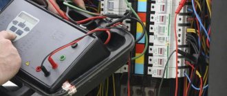
In order to assess how well such insulation “works”, its resistance is measured - their results are the main value in the work of electrical specialists.
The first measurement is carried out at the cable manufacturer, then during installation and subsequently during the entire period of use of the cable product. This is due to the fact that insulation is influenced by factors such as weather, period of its use, quantity, frequency of damage on the line, etc.
Components of a protocol
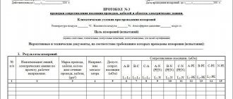
The document is filled out on one side of the sheet. In the upper part on the left is the full name of the measurement contractor with address data. Information in the same format about the customer is also required. Below in the form is the name of the agreement. Next to it is the document number entered in the registers. The date of signature is also indicated here.
For the convenience of providing information, specific data on cables and their conductivity, according to measurements, are presented in the form of two tables. The first has the following columns:
- Serial number.
- The name of the accession.
- Cable brand, number of cores, their cross-section. If possible, it is necessary to indicate whether there is insulation on the cable cores and what material the conductor is made of (the default is copper, but there are also options for conductors with an outer copper sheath and an internal aluminum content). If a wire is examined for resistance, then you also need to indicate how many wires it has and whether it is insulated.
- Insulation resistance in L–N core.
- Insulation resistance in L–PE.
- Insulation resistance in N–PE.
- Conclusion on compliance. Here we mean meeting the requirements of PUE clause 1.8.37 (7th ed.) for electrical wiring and PUE clause 1.8.40 (7th ed.) for cable lines.
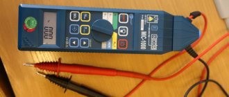
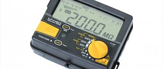
The second describes the equipment used for measurements and consists of columns with information such as:
- serial number;
- device name;
- type;
- factory number;
- range of available measurements;
- basic error;
- certificate number;
- date of last check;
- date of the next device check.
Both tables can contain one or several rows. Measurements cannot be carried out without equipment at all, so filling out the second table if the document exists is mandatory. At the very end of the tables, the regulatory document must be indicated (GOST, PUE, SaNPiN, PTEEP, instructions RD and SO., etc.), for compliance with which the insulation of a specific single-phase circuit was tested.
Based on these tables and the information found in the documents, a conclusion must be made: whether the conductor insulation meets the stated requirements or not. It is formulated in writing, in a special column “Conclusion”. The form provides only one line for this, since one word or sentence “complies” or “does not correspond” will be enough.
As-built documentation
Download different protocols for construction:
Protocols over communication networks:
1 Protocol for measuring the OB attenuation of mounted cables in regeneration areas, example,
2 Protocol for measuring the insulation resistance of the outer polyethylene shell of the FOC (armored cover - “earth”) at the installed regeneration section, form,
3 DC cable measurement protocol, example,
4 Optical crossover installation protocol, example,
5 Optical coupling installation protocol, example,
6 Protocol for incoming inspection of building lengths OK, example.
7 OK control protocol after installation, example
8 Balanced cable testing protocol (form 16 MVLKS), form,
9 Protocol for testing coaxial cable type KM-4, MKT-4 (form 17 MVLKS), form,
10 Protocol for electrical measurements of security at the far end (Form 6 MVLKS), form,
11 Protocol of electrical measurements with direct current of single-coaxial cable type VKPA (form 11 MVLKS), form,
12 Protocol of electrical measurements with direct current of coaxial cable type KM-4 (Form 9 MVLKS), form,
13 Protocol of electrical measurements with direct current of small-sized coaxial cable type MKT-4 (form 10 MVLKS), form,
14 Protocol of electrical measurements of a symmetrical cable with direct current (form 4 MVLKS), form,
15 Protocol for electrical measurements of transient attenuation at the near end (Form 5 MVLKS), form,
16 Protocol for measurements of cable transient attenuation, form,
17 Protocol for measuring potentials on the cable sheath (Form 7 MVLKS), form,
18 UTP cable measurement protocol - twisted pair, example, .
19 Measuring protocol for RG coaxial cable, example,
20 Measurement protocol for UNITRONIC LIHCH 16x2 cable, example,
21 Protocol for measuring cables with direct current (for copper cables such as TPP), form,
22 Protocol for measuring cable lines restored using UVK-MM2, example,
23 Protocol for measuring the construction length of a fiber-optic cable after installation, form
,
24 Protocol for measuring the construction length of a fiber-optic cable after installation, example
,
25 Protocol for input control of the construction length of the fiber optic cable FOC, example,
26 Optical splitter measurement protocol, example,
27 Protocol for checking the presence of a circuit between groundings, grounded installations and elements of grounded installations, example,
28 Protocol for measuring the insulation resistance of the outer polyethylene shell of the FOC (armored cover - ground) at the installed regeneration site, example
,
29 Protocol for checking the measurement of attenuation of the regeneration section with an optical tester, example,
30 Test report for compatibility when splicing optical fibers from different manufacturers, example,
Protocol for electrical installation work:
1 Protocol for measuring the resistance of grounding devices, form,
2 Protocol for testing the resistance of grounding conductors and grounding devices, example 1,
3 Protocol for testing the resistance of grounding conductors and grounding devices, example 2 +
,
4 Protocol for testing the resistance of grounding conductors and grounding devices, example 3 +
,
5 Protocol for testing the resistance of grounding conductors and grounding devices, example 4
+ ,
6 Power cable test report, example
+
,
7 Protocol for measuring insulation resistance, form,
8 Insulation resistance measurement protocol, example
+
,
9 Protocol for checking the insulation resistance of wires and cables, example 1,
10 Protocol for checking the insulation resistance of wires and cables, example 2
+ +
,
11 Protocol for checking the insulation resistance of wires, cables and windings, example 3
+
,
12 Protocol for inspection and checking the insulation resistance of cables on a drum before installation, example,
13 Insulation test report for increased AC voltage, example
+
,
14 Protocol for checking the impedance of the phase-zero loop, form,
15 Protocol for checking the phase-zero circuit in electrical installations with voltages up to 1000V with solid grounding of the neutral, example 1,
16 Protocol for checking the phase-zero circuit in electrical installations with voltages up to 1000V with solid grounding of the neutral, example 2,
17 Protocol for checking the circuit between grounding conductors and grounded elements, example 1,
18 Protocol for checking the circuit between grounded installations and elements of a grounded installation, example
+,
19 Protocol for checking the circuit between grounding conductors and grounded elements, example 2
+
,
20 Protocol for checking the conditions for triggering the RCD, form,
21 Protocol for testing instantaneous releases of automatic circuit breakers in electrical installations with voltages up to 1000V, example 1,
22 Protocol for testing instantaneous releases of automatic circuit breakers in electrical installations with voltages up to 1000V, example 2
+
+
,
23 Protocol for testing an electric gas switch and setting up devices, example
++
,
24 Circuit breaker test report, example
+ ,
25 Test protocol for circuit breakers, example +
,
26 Test report for power transformer, example 1
+ ,
27 Test report for power transformer, example 2,
28 Power transformer test report, example 3
+
+
+,
29 Protocol for measuring battery voltage, example,
30 Protocol for measuring battery insulation resistance, example
,
31 Test report for increased AC voltage, example,
32 Test protocol for arresters and arresters, example,
33 Test report for testing a 10kV power cable line, example
+
,
34 Acceptance test report for cable AVBbShv 4x70, example
35 Acceptance test report for cable AVBbShv 4x185, example, .
36 Acceptance test report for cable AVBbShv 4x240, example,
37 Protocol for visual inspection of an electrical installation, example +
,
38 Protocol for visual inspection of electrical installations, example
++
,
39 Test report for cable line terminations, example
+,
40 Protocol for the presence and quality of connections between equipment and a grounding device, example +
,
41 Test report for busbars and connecting busbars, example +
,
42 Cable line test report, example
+
,
43 Test report for cable lines up to 1000V, example
+
,
44 Protocol for checking the secondary switching of the cabinet, example ++,
45 Low voltage assembly test report, example +
,
Fire alarm protocol:
1 Protocol for heating cables on reels, form,
Protocol for installation of elevators:
1 Protocol for checking the operation of the elevator, form,
2 Test and measurement report for a full technical examination of the elevator (from an accredited testing laboratory), form,
3 Protocol for checking the technical documentation for the elevator (from an accredited testing laboratory), form,
Protocol of Russian Railways (railroads):
1 Test report for bushings, form,
2 Protocol for checking differential protection with RNT series relays, form,
3 Test report for single-phase voltage transformer, form,
4 Test report for three-phase voltage transformer, form,
5 Test report for oil-filled current transformer, form,
6 Test report for disconnector, form,
7 Test report for tubular arresters, form,
8 Power transformer test report, form,
9 Dry reactor test report, form,
10 Protocol for checking the impedance of the phase-zero loop, form,
11 Protocol of acceptance and preventive tests of the generator installed at the power plant, form,
12 Protocol for adjustment and testing of oil switch, form,
13 Test report for solid insulation current transformer (built-in), form ,
14 Cable test report, form,
15 Test report for support, suspension, bushing insulators, form,
16 Test report for the resistance to spreading of the ground loop, form ,
17 Protocol for checking the presence of a circuit between grounding conductors and grounded elements, form,
18 Test report for valve arresters and surge suppressors, form,
19 Insulation test report in switchgear, form,
20 Test report for mechanic belts, claws, belts, form,
21 Test report for voltage indicators, form,
22 Test report for voltage indicator for phasing, form,
23 Test report for insulating rods, clamps, form,
24 Test report for protective equipment made of dielectric rubber (gloves, galoshes, boots), form,
25 Test report for tools with insulated handles, form,
26 Oil test and analysis report, form,
27 Test report for the filter device of a traction substation, form,
28 Protocol for checking earth protection of 6-10 kV connections, form,
29 Test report for high-speed circuit breaker, form,
30 Protocol for testing differential protection with relays of the DZT-10 series, form,
31 Semiconductor converter test report, form,
Protocol on civil works:
1 Report of the results of radiographic testing of welded joints, form,
2 Report of mechanical tests of welded joints, form,
3 Report of the results of ultrasonic testing of welded joints, form,
4 Drilling protocol, form
5 Test report for control concrete samples for compressive strength, example
,
6 Soil sampling protocol, example
+
,
7 Protocol for determining the degree of soil compaction, example with appendix,
8 Protocol for determining the degree of sand compaction, example with appendix,
9 Test protocol for concrete cube samples, example,
10 Core test report example,
11 Protocol for drilling a well using the HDD method, form,
Return to the section: “Acts, protocol diagrams, etc.”
See the composition of the executive in the section: “Composition of the executive”
Download acts, protocols and more in the section: “Acts and other”
Download useful books, GOSTs, SNIPs in the section: “GOSTs and books“
Who makes the measurements
An important role is played by who carried out the resistance measurements. The protocol will not have legal force if the employees of the institution who compose and fill it out do not have the appropriate qualifications for this occupation.
Important! A specially trained electrical engineer takes measurements, checks against regulations and signs at the end to ensure that the information is correct.
Also, after the conclusion, the testing engineer and the head of the laboratory must sign. Then everything is certified by the seal of the institution that carried out the measurements. It is worth noting that, at the request of the customer, many electrical laboratories can draw up defect reports (if the inspection reveals faults in any single-phase circuit equipment) and provide a service to eliminate the identified shortcomings and problems.
Why is an insulation resistance test necessary?
If you do not regularly check the insulation resistance of electric motors , after some time it may dry out or become severely worn out and cease to perform its protective functions. And this situation is fraught with serious consequences, of which a short circuit is the most unpleasant. The consequence is often the ignition of insulation and other flammable materials, which gradually develops into a full-scale fire.
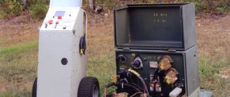
Motor insulation resistance measurement
That is why organizing and carrying out measurements of the insulation resistance of an electric motor is the primary task of the services responsible for maintaining electrical equipment in working condition. Its timely implementation in accordance with the approved work schedule will avoid serious consequences (prevent the failure of expensive equipment).
Insulation resistance standards
As with other elements of electrical equipment, for electric motors and similar DC machines, there are limit values for the conductivity of protective insulation. If the actual indicator turns out to be below the permissible limit when measured, the unit is removed from service.
Standards for asynchronous motors
According to the PUE, when measuring the insulation resistance of electric motor windings, the specific design and declared power of the unit should be taken into account. Only after all these factors have been taken into account can you begin to measure the controlled parameter
Taking these factors into account, the indicator being checked must correspond to the following values:
- For stator windings - at least 0.5 mOhm;
- For the motor rotor - at least 0.2 mOhm;
- The indicator for thermal sensors is not standardized.
Additional information: An approximate estimate, often used in measurement practice, is based on a value of this indicator not lower than 1 mOhm.
Its decrease to 0.5 mOhm, for example, indicates minor deviations from the norm, which, nevertheless, lead to serious consequences over time. If a significant decrease in this indicator is detected, it is best to send the questionable unit for examination to a specialized workshop.
Standards for DC machines
Testing techniques for DC machines are somewhat different from the procedures already discussed for asynchronous motors. Here you will first need to remove the brushes from the brush holders (alternatively, place a piece of insulating material under their body).
Checking the minimum insulation resistance is organized between the following nodes and circuit elements:
- between all exciting windings and the collector;
- between the brush holder and the base (body) of the unit;
- between the armature collector and the base;
- as well as between the exciting windings and the unit body.
Important! During the test, the field coils are electrically disconnected from other components and each is checked individually.
The permissible insulation resistance is determined by a number of factors, the main of which are the operating voltage of the unit and the air temperature. With an average of 20°C, it corresponds to the following values:
- at 220 Volts supply – 1.85 mOhm;
- at 380 or 440 Volts - 3.7 mOhm;
- in the case of a voltage of 660 Volts - 5.45 mOhm (the same indicator is provided for high-voltage machines of 6 kV or 10 kV).
In addition to the nodes considered, the resistance of the bandages is controlled. It is measured between itself and the housing, and, in addition, between it and the fixed motor winding. This indicator cannot be less than 0.5 mOhm.