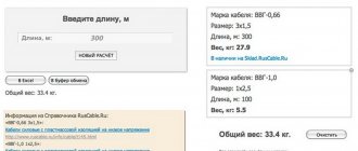
The power and current cable cross-section calculator will help you calculate the minimum cable cross-section required for safe operation of electrical wiring to avoid overheating, insulation melting, short circuits and fires.
The calculator allows you to calculate the cable cross-section by current or power, based on the parameters of the total load and incoming voltage. This takes into account the installation conditions, wire manufacturing materials, possible voltage losses and conductor selection criteria. The functionality of the section also allows you to calculate the maximum current and load on a conductor with specified parameters and select protection devices (circuit breakers, differential circuit breakers and RCDs).
How to calculate the cable cross-section:
- Indicate the source data (current or power), voltage, conductor material (copper or aluminum), type of wiring (open or closed in a pipe), number of wires (when laying communications in a pipe);
- Note additional conditions (wire length, permissible losses);
- Click on the “Calculate” button and save the resulting parameters.
The cable cross-section calculator works online and offline. Please note: it is for guidance only and cannot guarantee 100% accuracy of the calculations. However, the more valid data you enter into the appropriate fields, the higher the match rate will be.
Related regulatory documents:
- PUE-7 “Rules for electrical installations”
- SP 76.13330.2016 “Electrical devices”
- GOST R 50571.5.52-2011/IEC 60364-5-52:2009 “Low-voltage electrical installations. Selection and installation of electrical equipment"
- GOST 31946-2012 “Self-supporting insulated and protected wires for overhead power lines”
- GOST 31947-2012 “Wires and cables for electrical installations for rated voltage up to 450/750 V”
- GOST 6323-79 “Wires with polyvinyl chloride insulation for electrical installations”
- GOST 31996-2012 “Power cables with plastic insulation for a rated voltage of 0.66; 1 and 3 kV"
- GOST 433-73 “Power cables with rubber insulation”
How to calculate cable cross-section by power: formula
Before choosing a cable cross-section based on power, you need to calculate its total value and make a list of electrical appliances located in the territory to which the cable is laid. The power must be indicated on each device; the corresponding units of measurement will be written next to it: W or kW (1 kW = 1000 W). Then you will need to add up the power of all equipment and get the total.
1️⃣ First step. The total power of all electrical appliances that can be connected to the network is calculated:
Psum = (P1 + P2 + .. + Pn) × Kс
- P1, P2 .. – power of electrical appliances, W;
- Kc – demand coefficient (probability of simultaneous operation of all devices), default is 1.
2️⃣ Second step. Then the rated current in the circuit is determined:
I = Psum / (U × cos ϕ)
- Psum – total power of electrical appliances;
- U – network voltage;
- cos ϕ – power factor (characterizes power losses), default is 0.92.
3️⃣ Third step. At the last stage, tables are used in accordance with the PUE (Electrical Installation Rules).
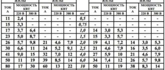
Table of copper cable cross-section by current according to PUE-7
| Conductor cross-section, mm2 | Current, A, for wires laid | |||||
| open | in one pipe | |||||
| two single-core | three single-core | four single-core | one two-wire | one three-wire | ||
| 0.5 | 11 | – | – | – | – | – |
| 0.75 | 15 | – | – | – | – | – |
| 1 | 17 | 16 | 15 | 14 | 15 | 14 |
| 1.2 | 20 | 18 | 16 | 15 | 16 | 14.5 |
| 1.5 | 23 | 19 | 17 | 16 | 18 | 15 |
| 2 | 26 | 24 | 22 | 20 | 23 | 19 |
| 2.5 | 30 | 27 | 25 | 25 | 25 | 21 |
| 3 | 34 | 32 | 28 | 26 | 28 | 24 |
| 4 | 41 | 38 | 35 | 30 | 32 | 27 |
| 5 | 46 | 42 | 39 | 34 | 37 | 31 |
| 6 | 50 | 46 | 42 | 40 | 40 | 34 |
| 8 | 62 | 54 | 51 | 46 | 48 | 43 |
| 10 | 80 | 70 | 60 | 50 | 55 | 50 |
| 16 | 100 | 85 | 80 | 75 | 80 | 70 |
| 25 | 140 | 115 | 100 | 90 | 100 | 85 |
| 35 | 170 | 135 | 125 | 115 | 125 | 100 |
| 50 | 215 | 185 | 170 | 150 | 160 | 135 |
| 70 | 270 | 225 | 210 | 185 | 195 | 175 |
| 95 | 330 | 275 | 255 | 225 | 245 | 215 |
| 120 | 385 | 315 | 290 | 260 | 295 | 250 |
| 150 | 440 | 360 | 330 | – | – | – |
| 185 | 510 | – | – | – | – | – |
| 240 | 605 | – | – | – | – | – |
| 300 | 695 | – | – | – | – | – |
| 400 | 830 | – | – | – | – | – |
Table of cross-section of aluminum cable by current according to PUE-7
| Conductor cross-section, mm2 | Current, A, for wires laid | |||||
| open | in one pipe | |||||
| two single-core | three single-core | four single-core | one two-wire | one three-wire | ||
| 2 | 21 | 19 | 18 | 15 | 17 | 14 |
| 2.5 | 24 | 20 | 19 | 19 | 19 | 16 |
| 3 | 27 | 24 | 22 | 21 | 22 | 18 |
| 4 | 32 | 28 | 28 | 23 | 25 | 21 |
| 5 | 36 | 32 | 30 | 27 | 28 | 24 |
| 6 | 39 | 36 | 32 | 30 | 31 | 26 |
| 8 | 46 | 43 | 40 | 37 | 38 | 32 |
| 10 | 60 | 50 | 47 | 39 | 42 | 38 |
| 16 | 75 | 60 | 60 | 55 | 60 | 55 |
| 25 | 105 | 85 | 80 | 70 | 75 | 65 |
| 35 | 130 | 100 | 95 | 85 | 95 | 75 |
| 50 | 165 | 140 | 130 | 120 | 125 | 105 |
| 70 | 210 | 175 | 165 | 140 | 150 | 135 |
| 95 | 255 | 215 | 200 | 175 | 190 | 165 |
| 120 | 295 | 245 | 220 | 200 | 230 | 190 |
| 150 | 340 | 275 | 255 | – | – | – |
| 185 | 390 | – | – | – | – | – |
| 240 | 465 | – | – | – | – | – |
| 300 | 535 | – | – | – | – | – |
| 400 | 645 | – | – | – | – | – |
In the Electrical Installation Rules, 7th edition, there are no tables of cable cross-section by power, there is only data on current strength. Therefore, when calculating sections using load tables on the Internet, you risk getting incorrect results.
How many kilowatts will SIP withstand?
While browsing the internet for electrical installations, I found a thread on one forum discussing “whether a 4x16 sip can withstand 15 kW.” The question arises because 15 kW 380 volts are allocated for connecting a private house. Well, people are wondering if it’s not enough to lay 16 square meters on a branch from the overhead line? I first looked into the PUE, but for some reason I didn’t find anything there on the topic of SIP power.
There is only plate 1.3.29 “Permissible long-term current for non-insulated wires according to GOST 839-80.” And it shows that the maximum permissible current for the cross section is 16 kV. mm. wire type AC, ASKS, ASK outdoors is 111 amperes. Well, at least something to start with.
How many kilowatts can a 4x16 SIP withstand?
But there is GOST 31943-2012 “Self-supporting insulated and protected wires for overhead power lines.” At the end of the standard, in paragraph 10 of the operating instructions, there is a sign
How many kilowatts can SIP withstand - table:
SIP section voltage 380V (3-phase load) voltage 220V (1-phase load)
| SIP 4x16 | 62 kW | 22 kW |
| SIP 4x25 | 80 kW | 29 kW |
| SIP 4x35 | 99 kW | 35 kW |
| SIP 4x50 | 121 kW | 43 kW |
| SIP 4x70 | 149 kW | 53 kW |
| SIP 4x95 | 186 kW | 66 kW |
| SIP 4x120 | 211 kW | 75 kW |
| SIP 4x150 | 236 kW | 84 kW |
| SIP 4x185 | 270 kW | 96 kW |
| SIP 4x240 | 320 kW | 113 kW |
Calculation method (update from 02/19/2018)
We take plate 10 and from it we find that one core is 16 sq. mm. withstands - 100 amperes. Next, we take the following calculation formulas:
for single-phase load 220V P=U*I
for three-phase load 380V P=(I1+I2+I3)\3*cos φ*1.732*0.38
update from 02/19/2018 Regarding the calculation of power for a three-phase load, you need to understand that a lot depends on the type of consumers (more precisely, what kind of load they provide active or reactive, it depends on what cos φ should be substituted into the formula, in this case for calculations it is equal to 0.95 )
Dear visitors to the site, I might not have noticed your caustic but technically correct comments on the article if just today a person called me with the question: “what kind of sip do I need for 120 kW?” According to the sign, a SIP with a cross section of 50 mm square would be perfect for him. Even if we omit the fact that the length of the line affects the voltage drop (it has 150 meters), we should not forget that the load on the phases can vary, as can be seen from the formula - it takes the average value for three phases. Here you just need to understand that the phase current can exceed the maximum permissible values for a given wire cross-section.
Therefore, if the value of the load you need is closer than 10% to the table, you should choose a larger section of the vulture from the list. Let me explain with the example of 120 kW. According to the table, for this three-phase load, a SIP with a conductor cross-section of 50 mm is suitable, but this is less than 10%. That is, 121 kW * 0.9 = 109 kW. Accordingly, you need to choose SIP 3x70+1x54.6.
At the beginning of the topic, the question was raised: “will a 4x16 15kW sip handle it?” Therefore, for a private house we multiply 220Vx100A = 22 kW per phase. But don’t forget that we have three phases. And this is already 66 kilowatts in total for a residential building. Which is a 4-fold margin relative to the issued technical conditions.
zakenergo.ru
Selecting cable cross-section based on current strength: calculation formula
The amount of current passing through a conductor depends on the length, width, resistivity of the latter and on temperature. When heated, the electric current decreases.
1️⃣ First step. The calculation is carried out in exactly the same way, that is, first the total power of all electrical appliances that can be connected to the network is calculated:
Psum = (P1 + P2 + .. + Pn) × Kс
- P1, P2 .. – power of electrical appliances, W;
- Kc – demand coefficient (probability of simultaneous operation of all devices), default is 1.
2️⃣ Second step. Then the rated current in the circuit is determined:
I = Psum / (U × cos ϕ)
- Psum – total power of electrical appliances;
- U – network voltage;
- cos ϕ – power factor (characterizes power losses), default is 0.92.
3️⃣ Third step. At the last stage, the same tables are used, according to the PUE (Electrical Installation Rules), which are located above.
Calculation of cable cross-section by length: formula
The cable length affects the voltage loss. Thus, the voltage at the end of the conductor may decrease and be insufficient to operate the electrical appliance. For household electrical networks, these losses can be neglected. It will be enough to take a cable 10-15 cm longer. This reserve will be used for switching and connection. If the ends of the wire are connected to the shield, then the spare length should be even greater, since circuit breakers will be connected.
1️⃣ First step. First, the rated current in the circuit is determined:
I = Psum / (U × cos ϕ)
- Psum – total power of electrical appliances;
- U – network voltage;
- cos ϕ – power factor (characterizes power losses), default is 0.92.
2️⃣ Second step. Then the conductor resistance is calculated:
R = dU/I
- dU – voltage loss, no more than 5% (0.05);
- I – current strength.
3️⃣ Third step. The cross-section of the current-carrying conductor is calculated using the formula:
S = ρ × L/R
- ρ – metal resistivity, copper (0.0175), aluminum (0.028);
- L – conductor length;
- R – conductor resistance.
Unique online services
Search system "Cable. Online" for the convenience of users has placed several important and unique online services that help:
· Calculate the weight characteristics of cable products and drums for transportation.
· Calculate the diameter of cable products in a matter of seconds.
· Select the optimal scheme for loading drums in a container or vehicle.
For example, the system instantly calculates that drums can be placed in an onboard KamAZ truck with dimensions of 6100x2400 mm:
· No. 6, with dimensions 600×370 mm, 5 units;
· No. 10, with dimensions 1000×650 mm, 9 units;
· No. 8b, with dimensions 800×620 mm, 5 units.
With this calculation, all safety requirements for the maximum distance between drums - 10 cm and the distance between the drum and the side - 5 cm will be met.
How to choose cable sections?
There are several more criteria that the cross-section of the wires used must meet:
- Length of cable
. The longer the wire, the greater the current loss observed in it. This again occurs as a result of an increase in resistance, which increases as the length of the conductor increases. This is especially noticeable when using aluminum wiring. When using copper wires to organize electrical wiring in an apartment, the length, as a rule, is not taken into account - the standard margin of 20–30% (for hidden wiring) is more than enough to compensate for possible increases in resistance associated with the length of the wire. - Type of wires used
. There are 2 types of conductors used in household electricity supply - copper or aluminum based. Copper wires are of better quality and have less resistance, but aluminum wires are cheaper. In full compliance with the standards, aluminum wiring copes with its tasks no worse than copper, so you need to carefully weigh your choice before purchasing a wire. - Electrical panel configuration
. If all the wires supplying consumers are connected to one circuit breaker, then it will be the weak point in the system. A heavy load will lead to heating of the terminal blocks, and non-compliance with the rating will lead to its constant operation. It is recommended to divide the electrical wiring into several “beams” with the installation of a separate machine.
In order to determine the exact data for choosing the cross-section of electrical wiring cables, it is necessary to take into account any, even the most insignificant parameters, such as:
- Type and type of insulation of electrical wiring;
- Length of sections;
- Laying methods and options;
- Features of temperature conditions;
- Humidity level and percentage;
- The maximum possible value of superheat;
- The difference in the powers of all current receivers belonging to the same group. All these and many other indicators can significantly increase the efficiency and benefits of energy use on any scale. In addition, correct calculations will help avoid cases of overheating or rapid abrasion of the insulating layer.
In order to correctly determine the optimal cable cross-section for any human household needs, it is necessary in all general cases to use the standardized following rules:
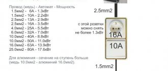
- for all sockets that will be installed in the apartment, it is necessary to use wires with an appropriate cross-section of 3.5 mm²;
- for all spotlighting elements, it is necessary to use electrical wiring cables with a cross-section of 1.5 mm²;
- As for high-power devices, cables with a cross-section of 4-6 mm² should be used.
If some doubts arise during the installation or calculation process, it is better not to act blindly. The ideal option would be to refer to the appropriate table of calculations and standards.
Table: Cable cross-section for closed and open wiring
Video: How to choose a wire cross-section?
Open and closed wiring
Depending on the placement, wiring is divided into 2 main types: closed and open.
Today, hidden wiring is installed in apartments. Special recesses are created in the walls and ceilings to accommodate cables. After installing the conductors, the recesses are plastered. Copper wires are used. Everything is planned in advance, because over time, to build up electrical wiring or replace elements, you will have to dismantle the finishing. For hidden finishing, wires and cables that have a flat shape are often used.
When laid open, the wires are installed along the surface of the room. Advantages are given to flexible conductors that have a round shape. They are easy to install in cable channels and pass through the corrugation. When calculating the load on the cable, the method of laying the wiring is taken into account.
What kind of insulation and sheath should the cable have?
It is best when the insulation and sheath of the cable are double insulated. A single-insulated cable has a service life of up to 15 years, while a double-insulated cable usually lasts 2 times longer. Typically, “insulation” and “sheath” are 2 different materials. The insulation is the layer of dielectric material that goes immediately behind the conductive core, and the sheath is all the layers on top of the insulation. The sheath is intended to protect the cable from various mechanical influences. The cable may have a couple of layers of sheath made of different types of material. Certain types of shell that may be useful:
- Heat-resistant cables are designed for installation in rooms with high temperatures (saunas). Typically, the material used is fluoroplastic, with fiberglass on top. There are no special designations for such cables, i.e. if necessary, you need to seek help from reference books or catalogs, where the value of the “operating temperature” is indicated precisely;
- non-flammable, marked “ng” - indicates the ability to self-extinguish when the flame disappears, but cannot withstand high temperatures
- when the cable brand contains “FR” (fire resistant) and then E30, E90 or E120, then this cable can “function” in an open fire for 30, 90 or 120 minutes;
- cables with a polyethylene sheath can be pulled both in the soil and in an open way (for example, along the walls of houses);
- cables with insulation and sheath made of PVC (polyvinyl chloride) are used for pulling inside buildings (under plaster) or in cable ducts.

