For various reasons, accidents in electrical networks occur quite often. In the event of a short circuit, overcurrent has a detrimental effect on all electrical appliances. If protective measures are not taken, the consequence of an uncontrolled increase in current can be not only damage to electrical installations in the area from the accident site to the power source, but also the failure of the entire power system. To avoid negative consequences caused by accidents, different electrical protection schemes are used:
- cutoff;
- differential-phase;
- highly efficient maximum current protection of electrical circuits (MCP).
Of the listed types of protection, the most common is MTZ. This simple and reliable method of preventing dangerous line overloads has found wide application throughout the world due to its selectivity, that is, the ability to selectively respond to different situations.
Device and principle of operation
Structurally, MTZs consist of two important components: an automatic switch and a time relay. They can be combined in one structure or placed in separate blocks.
Differences from current cut-off
Of all types of protection, current cutoff is the leader in reliability. An example is the protection of a household electrical network with devices using fuses or batch machines. The current cut-off method guarantees de-energization of the protected circuit in emergency situations. But to restore the power supply, it is necessary to eliminate the cause of the cutoff and replace the fuse, or turn on the circuit breaker.
The disadvantage of such a system is that shutdown can occur not only due to a short circuit, but also as a result of even a short-term exceeding of the load current parameters. In addition, human intervention is required to restore protection. These shortcomings are not critical in a household network, but they are unacceptable when protecting branched power lines.
Due to the fact that MTZ designs include time relays that delay the operation of cut-off mechanisms, they briefly ignore voltage drops. In addition, current relays are designed in such a way that they return to their original position after eliminating the cause that caused the contacts to open.
It is these two factors that fundamentally distinguish MTZ from simple current cutoffs, with all their disadvantages.
Operating principle of MTZ
There is a dependent connection between the delay unit and the current relay, due to which the shutdown does not occur at the initial stage of current increase, but some time after the occurrence of an emergency situation. This period of time is too short for the current to reach a critical level that could damage the protected circuit. But this is enough to prevent possible false alarms of protective devices.
The operating principle of overcurrent protection systems resembles current cutoff protection. But the difference is that the current cutoff instantly breaks the circuit, and the MTZ does this after some predetermined time. This period, from the moment of emergency increase in current until it is cut off, is called the time delay. Depending on the goals and nature of the protection, each individual time step is set based on calculations.
The shortest time delay is set on the most remote sections of the lines. As the MTZ approaches the current source, the time delays increase. These values are determined by the time required for the protection to operate and are called selectivity levels. Networks built according to this principle form coverage areas of selectivity stages.
This approach provides protection for the damaged section, but does not completely disconnect the line, since the selectivity levels increase as the overcurrent protection system moves away from the accident site. The difference in step sizes allows protective devices located in adjacent areas to remain in a standby state until the current parameters are restored. Since the voltage returns to normal almost immediately after cutting off the zone with a short circuit, the accident does not affect the operation of adjacent areas.
Examples of using protection
MTZ is used:
- for the purpose of localizing and neutralizing interphase short circuits;
- to protect networks from short-term overloads;
- for de-energizing current transformers in emergency situations;
- as a protector when starting up powerful, volatile equipment.
The time delay is very useful when starting motors. The fact is that at the start, a significant increase in inrush currents is observed in the winding circuits, which protection systems can perceive as an emergency. Thanks to the small time delay, MTZ ignores changes in network parameters that occur during startup or self-starting of electric motors. In a short time, the current readings approach normal and the cause of the emergency shutdown is eliminated. This prevents false alarms.
An example of connecting an electric motor overcurrent protection is illustrated by the diagram in Figure 1. In this diagram, the time relay ensures a reliable start of the electric motor until the current relay reacts.
Figure 1. Overcurrent protection with time delay
The time delay works similarly for short-term overloads in the protected network, which are not associated with emergency short circuits. The cutoff operates only in cases where a significant excess of the nominal values occurs on the protected line, which exceeds the shutter speed in time.
To ensure reliable protection in practice, two-stage and even three-stage protection schemes for sections of circuits are often used. The standard three-stage protection characteristic is as follows (Fig. 2):
Rice. 2. Selectivity map of standard three-stage protection
The abscissa shows the current values, and the y-axis shows the delay time in seconds. The curve in the form of a hyperbola displays the reduction in protection time from increasing overloads. When the current reaches 170 A, the MTZ time countdown starts. The time delay is 0.2 s, after which a shutdown occurs at around 200 A. That is, a circuit break occurs if the protection of other devices fails.
2.2. Non-selective cutoffs
Protection of the head sections of electric power systems, as a rule, is subject to increased performance requirements. This is due to the need to ensure the stability of parallel operation of synchronous generators and the power system as a whole. The use of current cut-offs is not always effective, since due to the increased cross-sections of the conductors of the head lines, short-circuit currents for faults at the beginning and end of the line differ slightly. As a result, it is usually not possible to provide acceptable coverage and cutoff selectivity.
In such situations, non-selective current cut-offs can be used.
Non-selective cut-offs are current protection of the maximum type, which can act in case of damage not only within the controlled object on which they are installed, but also beyond its borders. The selectivity of the action of non-selective cut-offs is ensured by introducing a time delay or the use of additional technical means.
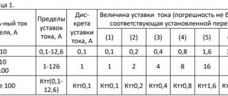
Calculation of current overcurrent protection
The stability of operation and reliability of operation of overcurrent protection depends on the settings of the operating current parameters. Calculations should ensure guaranteed operation of the relay in case of emergency, but its operation should not be affected by the parameters of the load current, as well as short-term surges that occur during engine starting mode.
It should be remembered that overly sensitive relays can cause false alarms. On the other hand, underestimated response parameters cannot guarantee the safe, stable operation of electrical appliances. Therefore, when calculating settings, it is necessary to choose a golden mean.
There is a formula for calculating the average current value to which an electromagnetic relay reacts [ ]:
Is.z. >In. Max.,
where I s.z. – the minimum primary current to which the protection must respond, and I n. max . – limit value of load current.
The relay return current is selected in such a way that it is sufficient to re-close the contacts in the used device. To determine it we use the formula:
I in = kn.×kz.×Iwork. Max.
Here I in – return current, k n . – reliability coefficient, k з – self-starting coefficient, I slave. max . – the value of the maximum operating current.
In order to bring the return and operation currents as close as possible, a return coefficient is introduced, calculated by the formula:
kв = I in / I s.z. taking into account which Iс.з. = kn.×kz.×Iwork. Max. /kv
Ideally, kв = 1, but in practice this coefficient is always less than one. The higher the value of kv, the higher the sensitivity of protection. Hence the conclusion: to increase sensitivity, it is necessary to select kv in a range tending to 1.
Literature
- Rules for electrical installations. M.: Gosenergonadzor of Russia, 1998, 608 p.
- Alexandrov A.M. Selection of tripping settings for protection of asynchronous electric motors with voltages above 1 kV. St. Petersburg: PEIPK, 2010
- Korolev E.P., Liberzon E.M. Calculations of permissible loads in current circuits of relay protection. - M.: "Energy", 1980/
- Shneerson E.M. Digital relay protection. M.: Energoatomizdat, 2007, 549 p.
- Korogodsky V.I., Kuzhekov S.L., Paperno L.B. Relay protection of electric motors with voltages above 1 kV. M.: Energoatomizdat, 1987
[1] There is an opinion that this term arose because the current cutoff algorithm provides protection only for part of the object, its compartment (see www.rza001.narod.ru).
[2] Traditionally, in digital devices produced by the Mechanotronics Research and Development Center, the characteristics of the first, second and third stages are designated as follows: I>>> (first stage), I>> (second stage), I> (third stage)
Gondurov S.A., Mikhalev S.V., Pirogov M.G., Zakharov O.G. Scientific and Technical Center "Mekhanotronics", St. Petersburg
Types of overcurrent protection
In electrical networks, 4 types of overcurrent protection are used. Their use is dictated by the conditions that need to be created for reliable operation of electrical equipment.
MTZ with current-independent time delay
In such devices, the time delay does not change. To set the settings for a period sufficient to activate relays with independent characteristics, selectivity stages are taken into account. Each subsequent shutter speed (towards the current source) increases from the previous one by a period of time corresponding to the selectivity stage. That is, during calculations it is necessary to comply with selectivity conditions.
Overcurrent protection with current-dependent time delay
In this protection, the process of setting the overcurrent protection settings requires more complex calculations. Dependent characteristics, in cases with induction relays, are selected according to the IEC standard: tсз = A / (kn - 1), where A, n are sensitivity coefficients , k = Iwork / Iaver - current multiplicity.
It follows from the formula that the time delay is no longer a constant. It depends on several parameters, including the strength of the current entering the relay windings, and this dependence is inverse. However, the shutter speed is not linear; its characteristic approaches hyperbole (Fig. 3). Such MTZ are used to protect against dangerous overloads.
Figure 3. Characteristics of MTZ with dependent time delay
MTZ with limited current-dependent time delay
Devices of this type of relay protection combine two stages of protection: a dependent part with a hyperbolic characteristic and an independent one. It is noteworthy that the time-current characteristic of the independent part is direct, smoothly conjugate with the hyperbola. At small multiples of critical currents, the dependent period characteristic is steeper, and at large multiples, the curve is flat (used to protect high-power electric motors).
MTZ with start (blocking) from a minimum voltage relay
In this type of differential protection, a combination of overcurrent protection is used using the influence of minimum voltage. In an electromechanical relay, the contacts will open only when the increase in current in the network leads to a drop in the potential difference. If the drop exceeds the lower limit of the set voltage, this will trigger the protection. Since the setting is set for a voltage drop, the relay will not respond to sudden surges in current in the network.
Setting settings [edit | edit code ]
When setting the overcurrent protection settings, the parameters of the operating current, time delay and operating voltage are set (for overcurrent protection with voltage blocking). For overcurrent protection with an independent response time delay from the current, these parameters are obvious. For protections with dependent and limited-dependent time-current characteristics, these parameters require additional explanation. For these types of overcurrent protection, the concept of operating current is introduced, as the current at which the relay is at the operating limit, and the time is set for the independent part of the characteristic (for a limited-dependent time-current characteristic); sometimes the time is set at a current equal to six times the rated current (for example, in circuit breakers with semiconductor releases of the A-37, “Electron” series).
Examples and description of MT circuits
In order to protect the windings of transformers, as well as other elements of networks with one-way power supply, various circuits are used.
MTZ on a constant operating current.
The peculiarity of this circuit is that the protection elements are controlled by rectified current, which changes polarity in response to emergency situations. Monitoring of voltage changes is performed by integral microelements.
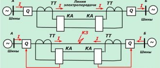
To protect lines from the consequences of phase-to-phase faults, two-phase circuits with two or one current relay are used.
Single-relay on operative current
This protection uses a current starting relay, which responds to changes in the potential difference between the two phases. Single-relay overcurrent protection responds to all interphase short circuits.
Scheme for 1 relay
Advantages : one current relay and only two wires for connection.
Flaws:
- relatively low sensitivity;
- insufficient reliability - if one protection element fails, a section of the circuit remains unprotected.
The single-relay is used in distribution networks where the voltage does not exceed 10 thousand V, as well as for the safe start of electric motors.
Two-relay on operative current
In this circuit, the current circuits form an incomplete star. The two-relay MTZ responds to emergency phase-to-phase short circuits.
Scheme for 2 relays
The disadvantages of this scheme include limited sensitivity. Overcurrent protection systems made using two-phase circuits are widely used, especially in networks where an isolated neutral is used. But with the addition of intermediate relays, they can operate in networks with a solidly grounded neutral.
Three-relay
The scheme is very reliable. It prevents the consequences of all short circuits, also reacting to single-phase faults. Three-phase circuits can be used in cases with a solidly grounded neutral, despite the fact that situations with inter-phase and single-phase faults are possible there.
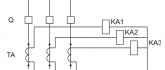
From Figure 4 you can understand the operating diagram of a three-phase, three-line overcurrent protection system.
Figure 4. Three-phase three-relay protection circuit
The diagram of a two-phase three-relay MTZ connection is shown in Figure 5.
Rice. 5. Scheme of two-phase three-relay connection of MTZ
The diagram shows:
- KA - current relay;
- KT - time relay;
- KL - intermediate relay;
- KH - indicator relay;
- YAT - trip coil;
- SQ - block contact that opens the circuit;
- TA - current transformer.
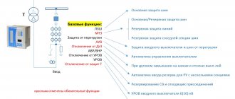
Implementation [edit | edit code]
Traditionally, MTZ are implemented on the basis of electromechanical current relays and time relays; sometimes the functions of the starting element and the time delay element can be combined (for example, in induction current relays of the RT-80 series). In the 1970s, implementations of MTZ based on semiconductor elements appeared (for example, in some models of domestic circuit breakers of the A37, VA, and Electron series). Currently, there is a tendency to implement MTZ on the basis of microprocessors, which usually, in addition to MTZ, also perform several functions of relay protection and automation: AFC, automatic reclosure, automatic transfer, differential protection, etc.