Using our calculator, you can calculate the cable cross-section by power (load) or current, taking into account the line length with a minimum error. The main indicators are the conductor material (copper, aluminum), voltage (220 V / 380 V) and load/current in the circuit. The method of laying the cable affects the cross-section of the conductor - closed cables require a larger cross-section, since due to limited heat transfer the metal heats up more. After carrying out the classic calculation for power/current, an additional calculation is carried out for the length of the conductor - the largest of the resulting pair of values is selected. The theoretical basis for the calculation is presented below in the form of formulas and tables. You may only be interested in the voltage loss calculator.
Related regulatory documents:
- PUE-7 “Rules for electrical installations”
- SP 76.13330.2016 “Electrical devices”
- GOST R 50571.5.52-2011/IEC 60364-5-52:2009 “Low-voltage electrical installations. Selection and installation of electrical equipment"
- GOST 31946-2012 “Self-supporting insulated and protected wires for overhead power lines”
- GOST 31947-2012 “Wires and cables for electrical installations for rated voltage up to 450/750 V”
- GOST 6323-79 “Wires with polyvinyl chloride insulation for electrical installations”
- GOST 31996-2012 “Power cables with plastic insulation for a rated voltage of 0.66; 1 and 3 kV"
- GOST 433-73 “Power cables with rubber insulation”
How to calculate cable cross-section by power?
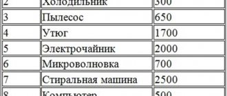
First step . The total power of all electrical appliances that can be connected to the network is calculated:
Psum = (P1 + P2 + .. + Pn) × Kс
- P1, P2 .. – power of electrical appliances, W;
- Kc – demand coefficient (probability of simultaneous operation of all devices), default is 1.
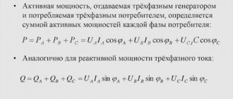
Second step . Then the rated current in the circuit is determined:
I = Psum / (U × cos ϕ)
- Psum – total power of electrical appliances;
- U – network voltage;
- cos ϕ – power factor (characterizes power losses), default is 0.92.
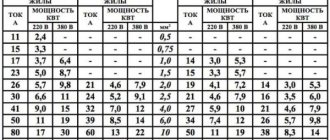
Third step . At the last stage, tables are used in accordance with the PUE (Electrical Installation Rules).
Table of copper cable cross-section by current according to PUE-7
| Conductor cross-section, mm2 | Current, A, for wires laid | |||||
| open | in one pipe | |||||
| two single-core | three single-core | four single-core | one two-wire | one three-wire | ||
| 0.5 | 11 | — | — | — | — | — |
| 0.75 | 15 | — | — | — | — | — |
| 1 | 17 | 16 | 15 | 14 | 15 | 14 |
| 1.2 | 20 | 18 | 16 | 15 | 16 | 14.5 |
| 1.5 | 23 | 19 | 17 | 16 | 18 | 15 |
| 2 | 26 | 24 | 22 | 20 | 23 | 19 |
| 2.5 | 30 | 27 | 25 | 25 | 25 | 21 |
| 3 | 34 | 32 | 28 | 26 | 28 | 24 |
| 4 | 41 | 38 | 35 | 30 | 32 | 27 |
| 5 | 46 | 42 | 39 | 34 | 37 | 31 |
| 6 | 50 | 46 | 42 | 40 | 40 | 34 |
| 8 | 62 | 54 | 51 | 46 | 48 | 43 |
| 10 | 80 | 70 | 60 | 50 | 55 | 50 |
| 16 | 100 | 85 | 80 | 75 | 80 | 70 |
| 25 | 140 | 115 | 100 | 90 | 100 | 85 |
| 35 | 170 | 135 | 125 | 115 | 125 | 100 |
| 50 | 215 | 185 | 170 | 150 | 160 | 135 |
| 70 | 270 | 225 | 210 | 185 | 195 | 175 |
| 95 | 330 | 275 | 255 | 225 | 245 | 215 |
| 120 | 385 | 315 | 290 | 260 | 295 | 250 |
| 150 | 440 | 360 | 330 | — | — | — |
| 185 | 510 | — | — | — | — | — |
| 240 | 605 | — | — | — | — | — |
| 300 | 695 | — | — | — | — | — |
| 400 | 830 | — | — | — | — | — |
Table of cross-section of aluminum cable by current according to PUE-7
| Conductor cross-section, mm2 | Current, A, for wires laid | |||||
| open | in one pipe | |||||
| two single-core | three single-core | four single-core | one-two-core | one three-wire | ||
| 2 | 21 | 19 | 18 | 15 | 17 | 14 |
| 2.5 | 24 | 20 | 19 | 19 | 19 | 16 |
| 3 | 27 | 24 | 22 | 21 | 22 | 18 |
| 4 | 32 | 28 | 28 | 23 | 25 | 21 |
| 5 | 36 | 32 | 30 | 27 | 28 | 24 |
| 6 | 39 | 36 | 32 | 30 | 31 | 26 |
| 8 | 46 | 43 | 40 | 37 | 38 | 32 |
| 10 | 60 | 50 | 47 | 39 | 42 | 38 |
| 16 | 75 | 60 | 60 | 55 | 60 | 55 |
| 25 | 105 | 85 | 80 | 70 | 75 | 65 |
| 35 | 130 | 100 | 95 | 85 | 95 | 75 |
| 50 | 165 | 140 | 130 | 120 | 125 | 105 |
| 70 | 210 | 175 | 165 | 140 | 150 | 135 |
| 95 | 255 | 215 | 200 | 175 | 190 | 165 |
| 120 | 295 | 245 | 220 | 200 | 230 | 190 |
| 150 | 340 | 275 | 255 | — | — | — |
| 185 | 390 | — | — | — | — | — |
| 240 | 465 | — | — | — | — | — |
| 300 | 535 | — | — | — | — | — |
| 400 | 645 | — | — | — | — | — |
In the electrical installation rules of the 7th edition there are no tables of cable cross-section by power , there is only data on current strength. Therefore, when calculating sections using load tables on the Internet, you risk getting incorrect results.
Causes of cable heating
For any network designed for domestic use or at a large industrial facility, it is imperative to correctly calculate the cross-section of cable and conductor elements. Knowing the reasons for temperature changes in conductors will help you perform this work correctly.
The physical nature of such a phenomenon as electric current lies in the clearly directed movement of charged particles that occurs under the influence of an electric field. In the working process, electrons are forced to overcome the internal bonds existing in the crystal lattice at the molecular level. Because of this, a significant amount of thermal energy is generated.
Like any other phenomenon, there are both negative and positive aspects of this property. In various devices, for example, irons, kettles, stoves, this effect is the basis of the design. But the downside is the threat of destruction of the insulation, which threatens equipment breakdown and even fire. Each such situation is an exceeding of the established limit by a long-term current load.
Excessive overheating is caused by:
- careless selection of section parameters. Before connecting the cable to the device, you need to make sure that there is a cable power reserve of about 30-40% of the rated operating consumption value;
- poor quality contacts will certainly cause heating and may result in a fire. The danger can often be eliminated by timely prevention in the form of tightening at the joints;
- the use of twisting for aluminum and copper conductors is unacceptable. You should use terminal blocks.
The correct data for the required cross-section can be obtained by dividing the sum of the rated powers of energy consumers by the voltage indicator. After this, it will not be difficult to determine the cross-section using the tables.
Selecting cable cross-section based on current strength
First step . The calculation is carried out in exactly the same way, that is, first the total power of all electrical appliances that can be connected to the network is calculated:
Psum = (P1 + P2 + .. + Pn) × Kс
- P1, P2 .. – power of electrical appliances, W;
- Kc – demand coefficient (probability of simultaneous operation of all devices), default is 1.
Second step . Then the rated current in the circuit is determined (for direct and alternating current (1-phase/3-phase), respectively):
I = Psum / UI = Psum / (U × cos ϕ) I = Psum / (U × cos ϕ × √3)
- Psum – total power of electrical appliances;
- U – network voltage;
- cos ϕ – power factor (characterizes power losses), default is 0.95.
Third step . At the last stage, the same tables are used, according to the PUE (Electrical Installation Rules), which are located above.
Heat transfer conditions
This process occurs with maximum efficiency when the cable is in a humid environment. The parameters are greatly influenced by the structure of the soil and its moisture content.
The most correct results are obtained by accurately determining the composition of the soil and clarifying its resistance indicators using special tables. If it is necessary to reduce heat transfer, the structure of the backfill is changed and compacted. For example, clay has greater thermal conductivity than gravel and sand. It follows from this that instead of stones and slag it is much more advisable to use loam and similar materials.
Minimum current load values are used in situations where conductors are located in cable ducts and other types of overhead lines. The optimal method for normal operation will be the calculation for operation both in normal long-term mode and in emergency mode. PVC cables can withstand a short circuit with a permissible temperature of 1200°C, and with a paper insulation layer - up to 2000 degrees.
There is an inverse proportional relationship between the temperature resistance of the conductor and the heat capacity of the external environment. At the same time, there is a difference in the cooling conditions of insulated and unsheathed wires.
During the calculation, it is important to provide for a reduction in the duration of the current load in each line when several cables are located in a common trench at once.
Cable selection
It is best to make internal wiring using copper wires. Although aluminum ones are not inferior to them. But there is one nuance here, which is associated with the correct connection of sections in the distribution box. As practice shows, connections often fail due to oxidation of the aluminum wire.
Another question is which wire to choose: single-core or stranded? Single-core has better current conductivity, so it is recommended for use in household electrical wiring. Multicore has high flexibility, which allows it to be bent in one place several times without compromising quality.
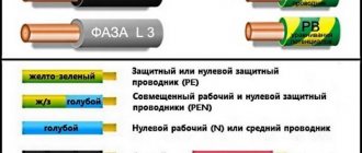
Single-core and multi-core wires
There is often confusion with this issue, including in articles published on Internet sites.
So, one wire can be used as a conductor in wires and cables - from the point of view of electrical conductivity, this is the best option.
But to achieve flexibility in cable products, it is necessary to use more complex structures - many thin wires, usually twisted into a “pigtail”. The more such wires, the more flexible the conductor becomes.
However, this should not be confused with stranded wire. A separate conductor means a separate conductor. To make it clearer, look at the illustration.
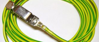
The picture below shows examples of single-core wire. It’s just that on the left side there is a rigid single-wire version, and on the right side there is a more flexible multi-wire version.
Both left and right are single-core wires.
If a wire (cable) structurally combines two or more conductors isolated from each other, it becomes two-core, three-core, etc. But it can also remain single- or multi-wire.
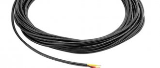
Double stranded wire
The situation is similar with cables. By definition, a cable is a structure of several conductors isolated from each other, enclosed in a common insulating and protective sheath. But conductors can also be single- or multi-wire.
Three-core power cables - solid or stranded
Rigid single-wire products are good for fixed sections of wiring, for example, embedded in walls. Stranded wires and cables are great for areas where mobility is needed - typical examples include power cords for household appliances and lighting fixtures.
So, all subsequent calculations will be carried out for the cross-section of the wire or cable core.
When assessing the conditions for the location of wires in the future, there may be options when you have to imagine the difference, for example, between three single-core wires stretched in one pipe, or one three-core cable.
Copper or aluminum
In the USSR, most residential buildings were equipped with aluminum wiring; this was a kind of norm, standard, and even dogma. No, this does not mean at all that the country was poor and there was a shortage of copper. Even in some cases it's the other way around.
But apparently the designers of electrical networks decided that they could save a lot economically if they used aluminum rather than copper. Indeed, the pace of construction was enormous; just remember the Khrushchev buildings, in which half of the country still lives, which means the effect of such savings was significant. There is no doubt about this.
However, today the realities are different, and aluminum wiring is not used in new residential premises, only copper. This is based on the rules of the PUE, clause 7.1.34 “Cables and wires with copper conductors should be used in buildings...”.
So, we strongly do not recommend that you experiment and try aluminum. Its disadvantages are obvious. Aluminum strands cannot be soldered and are also very difficult to weld; as a result, the contacts in the junction boxes may break over time. Aluminum is very fragile, two or three bends and the wire falls off.
There will be constant problems connecting it to sockets and switches. Again, if we talk about conducted power, then a copper wire with the same cross-section for aluminum is 2.5 mm2. allows a continuous current of 19A, and for copper 25A. Here the difference is more than 1 kW.
So let’s repeat it again - only copper! Further, we will proceed from the fact that we are calculating the cross-section for a copper wire, but in the tables we will also give values for aluminum. You never know.
Selecting the wire cross-section based on the number of consumers
What I also wanted to say is that it is better to use several independent power lines for each room in a room or apartment. Thus, you will not use a wire with a cross-section of 10 mm 2 for the entire apartment, routed to all rooms, from which there are taps.
Such a wire will come to the input machine, and then from it, in accordance with the power of the consumed load, selected wire sections will be routed for each of the rooms.
Typical electrical wiring diagram for an apartment or house with an electric stove (indicating the cable cross-section for electrical appliances)