All things tend to wear out over time. It is for this reason that every few years we renovate the apartment, re-sticking old wallpaper, changing flooring and baseboards, and rearranging sockets. But all these actions are only cosmetic. In the case of a major renovation or moving from an old apartment to a new one, there is much more work, some of which are recommended to be completed. These include replacing wiring. Today we will talk about how to replace old wiring.
Copper, earth and doses
Replacing electrical wiring in a residential area rests on three pillars:
- Replacing aluminum wires with copper ones.
- Transition from the power supply circuit TN–C (solidly grounded neutral) to TN–C–S (with protective grounding of consumers).
- Transition from branching wires to connecting groups with separate branches.
Let's explain in order:
Aluminum electrical wiring, due to its low cost and environmental friendliness (copper mining and smelting were extremely hazardous industries at that time), became widespread throughout the world in the 30s - 60s. However, over time it became clear that aluminum is unsuitable for electrical wires:
- Over the course of 20 years, changes occur in metal circuits under current, the essence of which is still not completely clear; First of all, aluminum becomes very brittle, and you literally can’t breathe on the wiring.
- At the slightest ingress of moisture, aluminum is susceptible to electrocorrosion, which spreads under the shell; A seemingly intact wire turns out to be thinned down to a hair; hence the sudden failures, the most emergency ones.
- Aluminum is a soft metal. It is squeezed out from under the terminal screws, the twists weaken, and soldering aluminum is difficult, expensive and one of the hazardous industries. Therefore, aluminum contacts are unreliable.
Power line wires have a service life of less than 20 years, and the defects of aluminum do not affect them. But aluminum is now prohibited in residential wiring.
The Soviet TN-C power supply scheme was used forcedly, due to the need for mass electrification in conditions of an acute shortage of non-ferrous metals and the large length of communications in a huge country. Since 1997, the TN-C-S power supply system has been adopted in the Russian Federation, ensuring consumer safety regardless of the state of the power grid. There are many ungrounded high-rise buildings left from the USSR, but since there is a problem, it needs to be solved; not “from above”, but on our own.
The branching wiring diagram was also used forcedly, and for the same reasons as TN-C. At the same time, branches to groups were connected to the more powerful apartment input wires along their length. Branches were made in distribution boxes - electrodispensers (doses); The main apartment dose is located next to the counter.
Each branch is stripped of insulation and twisted or terminals: unreliable and sensitive to locking. Nowadays it has not yet been legalized (but things are moving towards that), but branch wiring is commonly used: from the input to each group of connections there is a separate solid piece of cable in double or triple insulation. No twists or clamps, not afraid of moisture.
Methods for installing wiring in an apartment
It is important to immediately make a reservation that the following options will only be relevant for buildings with walls made of concrete or brick. They are not suitable for wooden houses, so the methods are not universal
The first method will be relevant for those houses where there is not even a layer of plaster on the walls. Then the wiring can be placed directly on the surface of the walls. There are also two methods here, which were already mentioned earlier:
- Place the cables in corrugated plastic pipes if the thickness of the finish allows.
- Simply lay the cables open if they have double or triple insulation.
The second method is encountered most often, because it is suitable for cases when:
- The plaster has already been applied.
- Its layer will not cover the wires and you will have to make grooves directly in the wall.
This is a more difficult and longer path, but most often it turns out to be the only suitable one. In addition to the fact that the grooves have to be made, the wires in them will also need to be carefully fixed - with plaster patches or plastic staples.
*(Dowel staples are especially suitable for ceiling wiring)
To make all the grooves correctly, it is better to make markings according to the diagram directly on the wall, then there will definitely not be any difficulties and there will be a chance to check everything again and correct something.
Now you need to determine how to lay the cables themselves. The lines from the distribution board to each junction box can be laid using the methods described in this table.
| Highway location | Peculiarities |
| Along the upper edge of the wall in a groove or corrugated pipe | Most often used |
| Over the floors until the floor screeds are poured (in plastic pipes) | This is the shortest way. Here, by the way, grooves are not useful either, since when the floor is filled, all the wires will be hidden. For such wiring, sockets built into baseboards are usually needed. By the way, now you can purchase special kits - a special plinth with cable channels, sockets, switches, junction boxes, etc. True, it is not suitable for any finish. |
| Along the ceiling | Here, most likely, you will have to make grooves, however, the consumption of materials will also be economical. Junction boxes can also be placed on the ceiling, but this will hardly be convenient when repairs are required. This method is only relevant when a suspended or suspended ceiling is intended to hide the lines. |
When installing the wiring yourself, only the first option is suitable, and despite the great advantages of the other two, it is no worse than them. It will just require more time, but since the plan to install the wiring with your own hands has reached the strobing stage, the hardest part is already over.
*(Grooves are the penultimate stage on the route of wiring)
Stages of work
Electrical wiring installation costs can be reduced by half or more. The fact is that replacing electrical wiring is carried out in five stages:
- Development of a power supply diagram for an apartment (house).
- Drawing up an electrical wiring plan, its approval and registration together with the power supply diagram.
- Construction of a temporary repair shed.
- Electrical wiring.
- Installation of mechanisms (switches, automatic machines), RCDs, connection points (sockets) and stationary electrical appliances (lighting fixtures, heated floors, washing machines, air conditioners, electric ovens, etc.).
Before starting work on replacing electrical wiring, protective grounding should be installed, if possible, or protective grounding should be provided. However, its structure is the topic of a separate article.
Wiring to points is carried out at the last stage during the installation of mechanisms, automation, connection points and electrical appliances.
You can save money at each stage of replacing electrical wiring. In general, you can reduce costs by half or more - up to 650-450 rubles per square meter, depending on what you can do on your own and what you will have to entrust to specialists.
Safety regulations
All work is performed with tools with insulated handles and wearing rubberized gloves. To groove walls at height, it is best to use a sawhorse or a stepladder with a horizontal stop. An ordinary stepladder is not reliable enough.
Replacing electrical wiring with your own hands is a rather difficult task, but it can be done if you know how to draw up and read electrical diagrams. Otherwise, it’s better not to take risks and contact professional electricians.
In conclusion, we suggest watching a video review on how to choose the right material and do the wiring yourself:
https://www.youtube.com/watch?v=fe01LgsLmCk
Power supply diagram
Take a look at the picture in the section. Just take a look for now. Let's give some explanations. Firstly: kWA – electricity meter; RCD – residual current device. Secondly, the power supply circuit is single-line.
Single-line diagram of apartment power supply
Pay attention to the two slashes that cross out the wire designation. This means that in reality there are two wires - phase L and zero N (neutral), laid together. The PE protective wire is not crossed out, which means it goes separately. If the input is three-phase, then there will be three dashes on the designations of its wires. We do not touch systems with an isolated neutral, which are not used in everyday life.
Now look at the drawing carefully. This is a single-line power supply diagram for an elite apartment of 200 square meters. m. If everything in it is generally clear to you, you will be able to draw your own power supply diagram, even if you do not have an electrical engineering education and do not know how to draw.
At worst, you will end up with a clumsy sketch. But using it, a senior student or a retired electrician looking for a part-time job will be able to draw the correct diagram in half an evening and inexpensively. And if you entrust the scheme to a practicing specialist with a decent salary, it will cost a pretty penny. The trouble will not decrease for you: after all, he needs the initial data.
Thinking through the power supply
Proper electrical wiring in the house depends primarily on the power consumption. In cottage villages they give a consumption limit of 10-20 kW for housing, but in a city apartment this is unrealistic: either the machine in the entrance will be knocked out all the time, or, even worse, the house wiring will burn out. And in old houses, where replacement of wiring is most often required, the “Khrushchev” limit is set at 1.3 kW; at the limit - 2 kW.
However, no one turns everything on at once. Even in the summer, when the air conditioners are on, they turn on out of step. Here, chance works for the consumer: with an average power consumption of 4.3 kW, the house wiring holds up. This limit is used as the basis for the calculation. True, if in the summer you start washing or ironing, the air conditioner with the boiler will have to be turned off, otherwise the main machine will turn off the entire apartment. But you have to come to terms with this.
Without going into the details of the calculation, we will immediately give data for an average city apartment of 40-100 square meters. m of total area:
- Main circuit breaker - from 25 to 32 A depending on the area. For the meticulous: the current safety factor is 1.3-1.5. It is impossible to give 2 in apartment buildings: the general wiring is “stunted”.
- Apartment RCD – 50 A 30 µA unbalance.
- Kitchen - two branches of wiring of 4 sq. mm; on each there is a 25 A automatic circuit breaker and a 30 A 30 µA RCD. Water supply to the bathroom is from the kitchen; not indicated on the diagram, see below.
- Air conditioning – branch 2.5 sq.mm; automatic – 16 A, RCD – 20 A 30 µA.
- Socket circuits and lighting circuits - one of both in each room, except for the bathroom and toilet; they contain only lighting; We're still talking about the bathroom. The cross-section of the prododes is 2.5 sq. mm; Automatic shutdown is not needed, a general apartment one will suffice.
That's all the source code for a single-line power supply diagram for an apartment. You can draw.
Figure: graphic diagrams for “clarification”:
Drawing a diagram
You can take the diagram shown in the very first figure as a basis. Its top, from the exit from the counter, remains unchanged, you only need to change the numerical data. The brand of the RCD does not matter: if you end up installing others instead of the ASTRO-UZO, this does not violate anything.
In case of doubt regarding the designations, see the Appendix to the PUE (Rules for the construction of electrical installations of consumers) or GOST 2.755-87 (CT SEV 5720-86). Just follow the GOST number: for some reason, in the search, a lot of references to GOST 2.721-74 and even GOST 7624-55 pop up, which are now no more useful than the Moral Code of the Builder of Communism, at one time personally edited by a dear comrade and unforgettable Secretary General Leonid Ilyich.
When drawing a diagram, observe the dimensions of the symbols of the elements: scaling them is not allowed. If, for example, an electric capacitor is indicated by two parallel lines 0.5 mm thick and 10 mm long at a distance of 2 mm from one another, then so be it, even if it is alone on a sheet of Whatman paper A0.
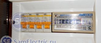
Distribution panel
The second important element of electrical wiring is the main distribution panel. At this point, the power is divided into individual electrical circuits and distributed through cables around the house. It also contains fuses, emergency devices and other items used to properly maintain the network.
In many old houses, such blocks have already been remodeled many times. Instead of fuses, we can find in them more modern switches for increased current, supplemented by a residual current switch. The latter protect against electric shock not only when directly touching, for example, the body of a device in which the insulation has been damaged, but also when touching a wire or contacts in a socket or switch.
The operation of the earth leakage switch is to compare the current flowing in the phase and neutral conductors, and if there is a significant difference, quickly turn off the power source. Differential current can also occur as a result of breakdown caused by damage to the insulation of conductors or dampness of electrical devices. It is most often used for old equipment that operates in high humidity conditions. The switch can then cut off the power very quickly.
Useful: Wiring diagram for a double switch for 2 light bulbs in a chandelier
The distribution board must be labeled - each fuse must have the name of the circuit on it. If there are visible signs of burnout, loose wires without insulation, or sloppy modifications, you should not use it, and install a portable switchgear while the network is being updated, which will ensure safe operation during repairs. It would be good to find out whether the previous owner of the house performed mandatory (every 5 years) measurements of the electrical safety of cables and accessories.
Preparing a plan
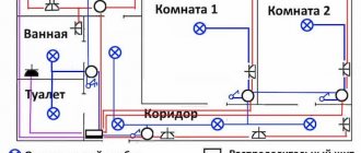
Now look at the picture that accompanies this section. This is already a PLAN for the electrical wiring: this is what the diagram turns into when you have to do it by hand. Let's explain the plan:
- At least two branches must go to each room from the meter - to the lighting circuit and the socket.
- Since an ordinary apartment has one bathroom, a DSU (additional potential equalization system) is not needed. Its branch in the diagram is indicated by a dotted line.
- In the bathroom, mark only the moisture-proof ceiling light and the boiler, if installed there. The bathroom is a special and complex case, we will talk about it later.
- Designate only branches to connection points (sockets) and stationary electrical installations. Stationary installations are considered to be those that are rigidly fixed to supporting structures, or that are not powered through a detachable connection. For example: the boiler and heated floor are stationary, but the washing machine, dishwasher and electric oven are not. The fact that they are connected to other communications does not concern or concern electricians.
- Do not clutter the circuit with small things like LED ceiling lighting, extension cord to the balcony, etc. Such things only irritate inspectors, and a completely decent plan can be “cut down.”
- Under no circumstances point branches onto a balcony or loggia! For a city apartment, this is a gross violation of the PUE. These rooms must be powered from outlets in other rooms.
Electrical wiring plan in the apartment (clickable)
And now we’ll show you how to simplify the preparation of the plan:
- Take a plan of your apartment from the DEZ or BTI.
- Scan; if large - in pieces.
- In Photoshop, glue the pieces together and remove the old markings for wiring, stationary electrical appliances and connection points.
- Apply new ones in accordance with the diagram and the sample wiring plan provided. It’s more convenient to do this not in Photoshop, but in CorelDraw or another vector graphics editor, by importing the original raster file and then exporting the finished plan back to a raster. Don't forget to save the vector template! Plans made by amateurs are returned for revision with comments in almost 100% of cases.
- In Photoshop, divide a large image at the required scale into parts the size of the print area of your printer, print and glue into a large sheet so that the lines coincide. If they move apart a little, you can draw it by hand.
Notes:
- If the bathroom is located far from the kitchen (as, for example, in Czech apartments), then the group of sockets provided for it, described below in the section on the kitchen, should be placed in the bathroom adjacent to it.
- It is advisable to place groups of sockets in adjacent rooms exactly opposite each other across the wall. In this case, by drilling into the wall, you can power both groups with one branch, saving cable and pipe.
- In “tram” apartments (enfilade layout) in the room farthest from the meter, groups of sockets, but no more than two, are allowed (in practice, not according to PUE) to be powered sequentially, one from the other. In this case, if the near group is powered through the wall from the living room, another half of the branch is saved.
- In practice, sconces and other local lights can also be powered from sockets or in series within the room if it also has a ceiling lamp.
- Ceiling lamps must be powered each by a separate branch. It is unacceptable to power them through each other or from sockets: general lighting circuits are considered vital.
- Rows of spotlights on the ceiling are counted and designated on the plan as a chandelier. The branch for them is led out to the center of the ceiling, and the wiring during installation is done as safer and more convenient.
The finished power supply diagram and wiring plan for the apartment must be registered and approved by the energy service. The verification and registration procedure is free.
Important: The electrical wiring plan should be given the utmost attention. Optimally, a properly drawn up plan saves costs by half or more compared to a sloppy one.
HOW TO FIND ELECTRICAL WIRING IN A WALL
Old cables must be removed, even if they are no longer connected. To find electrical wiring in an apartment, not only special electrical wiring testers are used, but also some tricks.
There are two types of devices for detecting hidden electrical wiring:
Household - for example, Meet MS-158M
.
In addition to search, it can perform a number of additional functions:
- check the integrity of the electrical network using resistance monitoring (up to 50 Ohms);
- non-contactly measure voltage in the range of 70-600 V;
- determine the polarity of conductors in DC electrical networks.
Despite such wide possibilities, the main characteristic is that the positioning accuracy of the electrical cable is quite mediocre, amounting to 7-10 cm.
Professional – model E121 “Woodpecker”
.
They have a narrow specialization. Detects a cable with an accuracy of 4-6 cm. At the same time, it has four modes that determine the depth of the conductor under the plaster layer.
There are other ways to detect conductors without using a wiring detector: radio, compass, microphone. They all begin to react to an electrical cable located nearby. The only drawback of such methods is the rather large error of up to 15 cm.
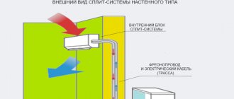
Electrical equipment of rooms
To draw up a power supply plan competently, you must first of all decide how many and what connection points and stationary consumers will be in the house. Of course, you are the master of your home, and it is impossible to develop a single methodology for drawing up a plan for all layout options. But the following guidelines may be useful to you.
Bathroom
Bathroom electrical installations are a tough nut to crack. On the one hand, only high humidity makes the bathroom particularly dangerous in terms of the degree of electric shock. Plus, there is a splashed floor and a naked, steamed person in hot water. The resistance of his body drops more than that of a dead drunk: the short circuit current through the body can exceed 5 A (!), and this is between an absolutely fatal blow and charring. The damaging effect of electric current depends on the time of exposure, and with such strength, the response time of the RCD is in no way sufficient to certainly prevent trouble.
On the other hand, there are powerful electrical installations: a washing machine, a boiler, with a large inherent leakage current, operating at elevated temperatures and humidity. In such conditions, exposed live contacts, even under the cover of the socket, will be a source of danger of electric shock.
PUEs allow the installation of sockets in the bathroom through an isolation transformer or RCD, but this decision is even more forced than the TN-C system was in its time. The RCD has already been mentioned, but as for the isolation transformer, this point was simply copied from the section on industrial electrical equipment for lack of a better one.
Installing an isolation transformer is a technically quite complex task and is the subject of a separate description. Recommendations like - pushing the RTR under the suspended ceiling in the bathroom - are the fruit, if not of ignorance, then of a latent desire for perverted electrosuicide. According to the letter PTB and PUE, a bathroom can only have a ceiling lamp in a waterproof design. But in the spirit and essence of the same PTB and PUE, the power supply to the bathroom can be organized as follows:
- Replace the electrical cords of the boiler and fan with long ones so that they are enough to go through the hole in the wall to the sockets in the kitchen or in the room adjacent to the bathroom. The boiler is not equipped with a standard cord, and the loss of the warranty on an inexpensive fan is not a big problem, especially since almost 100% of warranty returns of fans come down to non-warranty cases. Of course, the cords are three-core, with a protective conductor.
- Buy an extension cord without a cord, but with grounding contacts (Euro), for three sockets, with shaped holes in the back for hanging on the wall, and also provide it with a three-core cord.
- Lead all three cords through a hole in the wall in the corner above the baseboard into the kitchen or adjacent room, equip them with Euro plugs, and place them in a PVC box: in the corner and below it will not be conspicuous.
- The boiler plug is plugged into the socket “permanently” - nowhere in any rules is there a time limit for plugging the plug into the socket. Also the fan plug, if it is “intelligent” and is triggered by temperature and humidity.
- The extension cord is hung in the bathroom using self-tapping screws in dowels.
- The washing machine is plugged into the extension cord permanently. The remaining two sockets can be used to include a light frame for a mirror and a hair dryer.
- The extension cord plug is plugged into an outlet in the adjacent room as needed.
Thus, there will be no exposed live ends in the bathroom all the time, and if basic precautions are taken, the risk of electric shock will be reduced to zero. And according to the PUE and PTB, an extension cord, even with a cord in a box and hung on the wall, is just an extension cord, not a socket.
Toilet
Only one lighting branch for the ceiling lamp will go to the toilet, as well as to the bathroom. Toilet and bathroom fixtures can be powered sequentially using one branch: electricians do not find fault.
Kitchen
For the kitchen, therefore, you will need two branches of wiring: for the bathroom and for your own needs. If the bathroom is located away from the kitchen, then the branch for the bathroom will go into the room adjacent to it, but we will describe it here.
The wire cross-section is 4 sq. mm and the automatic protection for both branches is the same and is described above. But the connection points differ: for your own kitchen branch you need not one, as for the bathroom, but two triple sockets. They will always include a dishwasher, an electric oven, a food processor and spotlights. Powering the halogens on the bottom of a hanging cabinet with a separate branch, as is sometimes recommended, is uneconomical and incorrect according to the PUE.
One of the remaining points will go under the kitchen fan, and the other is constantly connected to an extension cord, hung, like in a bathroom, on a wall or on a cabinet. It can be used to plug in a toaster, a vacuum cleaner when cleaning, etc. The refrigerator is plugged into an additional group socket on the opposite wall.
It is advisable to place the bathroom and main group sockets behind the lower kitchen cabinet, close under the countertop, but away from the sink. If the bottom cabinet has a back wall, cut an opening in it. To pass the cords, cut off the back corners of the tabletops so that they are not visible, and the cords pass freely.
The lighting branch in the kitchen is the same as everywhere else.
Hallway and corridor
Two branches are needed here: for the socket and for the light. If the corridor is long and two lighting points are needed, then the one closest to the outlet is made in the form of a sconce and is powered from it. And the far point will already be a ceiling lamp, powered by its branch.
Children's
The PUE requires for children's institutions that sockets and switches be located at a height of at least 180 cm from the floor. But this applies only to institutions, and the child will grow up, and the room will remain his.
If your beloved child shows an increased interest in technology from a tender age, the socket in the nursery should be equipped with a protective disk. A socket with a key-locked lid can cause a petty individual to become sulky and suppress inclinations that may later become the key to success in life.
Living rooms
Without going into the intricacies of the topology, let's say right away: to power the ceiling lamps and two groups of sockets in living rooms, 2N+1 branches are enough, where N is the number of rooms. Let us explain using the example of a three-room apartment:
- Living room - 1 branch of the main socket group, 1 - additional, 1 - lighting.
- Bedroom – 1 branch of the main group, 1 lighting. The additional group is powered through the wall from the additional group in the living room.
- Children's - 1 branch of the main group, 1 lighting. The additional group is powered through the wall from the additional bedroom group.
- From the bedroom or children's room, depending on the layout, an additional kitchen group is powered through the wall.
In total, for a 2-3 room apartment you will need 12-15 branches, including air conditioning. The branch for the air conditioner must end with a socket, although it is a stationary device. For two reasons: for safety and ease of maintenance, and because the split is equipped with a standard molded cord, cutting which will void the warranty.
At what height will the sockets be?
The optimal height for sockets is 25-35 cm from the floor. It’s quite comfortable to reach for them, they don’t catch your eye, and they don’t interfere with furniture. The exception is the air conditioner outlet. It is placed higher so that its cord can be reached and not dangle in plain sight. Excess cord can be rolled into a coil and placed on top of the wall unit body; The height of the placement of sockets is not regulated anywhere.
Do not try to “over-wire” it beyond measure - this will only reduce the reliability of the wiring. Two groups, one double in each, is quite enough. As a last resort, a triple socket can be placed in one seat, but this cannot be built-in.
How to calculate cable length?
Using the diagram, you can make approximate calculations of the amount of cable if the exact dimensions of the rooms are taken into account. But they should be clarified and double-checked by transferring the diagram from paper to the walls. And this procedure is also carried out by professionals to determine as accurately as possible the placement of all sockets and switches, as well as the cables connecting them.
There are no clear standards at what height from the floor and at what distance from the corners the wires should run. Until recently, in Eastern Europe it was customary to install sockets at the level of the lowered arm, and switches at eye level, but it is now difficult to say where such standards came from.
Today, construction manuals typically provide the following information:
- Sockets are installed 30–35 centimeters from the floor (or 40–45 cm from the interfloor ceiling). Although they can be installed directly on baseboards, then the sockets must be special.
- The switches are at a height of about 90 cm, so that they can be used with their hands down and are also convenient for children.
It is important to note that these are standards for living rooms. For the kitchen, for example, they are different. Most of these rooms are occupied by countertops and cabinets, so sockets will need to be placed somewhere between them or even inside - hidden socket blocks in the form of a book or a “column” that rises when you press the lid are popular today
Most of these rooms are occupied by countertops and cabinets, so sockets will need to be placed somewhere between them or even inside - hidden socket blocks in the form of a book or a “column” that rises when you press the lid are popular today
Most of these rooms are occupied by countertops and cabinets, so sockets will need to be placed somewhere between them or even inside - hidden socket blocks in the form of a book or a “column” that rises when you press the lid are popular today.
There are also rules for bathtubs, in which sockets and switches are not placed at all, and everything is taken out of bounds. And if they are placed, then they are special, resistant to constant humidity and temperature changes.
For other rooms, the rules for laying the wiring are simple - the line should go straight down from the socket or switch (or up if the network is located under the ceiling). No ladders, corners or diagonal placements are allowed due to the danger of forgetting the location and then running into cables if you need to make a hole in the wall.
And to understand what wiring placement standards are in effect now, it’s worth studying this table.
| An object | Distance from object |
| Windows and doors | Not less than 10 cm |
| Heating pipe | Not less than 30 cm |
| Pipes with flammable substances (gas) | At least 40 cm |
| Ceiling | From 15 cm |
| Stretch ceiling | From 10 cm |
| Corner of the room | From 10 cm |
| Floor | At least 15-20 cm |
Tools and materials
You will need the following tool to replace electrical wiring:
- A hammer drill with a 16-20 mm concrete drill, a 90-100 mm core drill, a 25-30 mm concrete chisel and a set of drills, also for concrete.
- Grinder with a stone circle.
- Soldering iron 40-60 W.
- Phase indicator indicator.
- Multimeter tester.
- Pliers, screwdrivers and side cutters with insulated handles.
- Flashlight.
- Assembly knife.
- Construction level and cord for marking the groove route.
- Spatula for putting alabaster.
- Portable electric lamp.
We should talk specifically about materials.
Terminal blocks
The described method of replacing electrical wiring eliminates its twisting and soldering along the length, and the wiring turns out to be absolutely resistant to jamming. All connections will be made in the input panel (IC) at the terminal blocks and at the end points. Terminal blocks are sold in sections of 10 contacts (5 pairs). You will need 3-4 sections; It’s better to take three at once, and it’s never too late to buy.
When purchasing, pay attention to the material of the case - polyethylene is bad, any other will do. And most importantly, the holes for the wires should accommodate two wires with a diameter of 2.5 mm. It is better to immediately take terminal blocks with rectangular holes, in which the wires are clamped not directly with a screw, but with a special plate.
Socket boxes
Mounting boxes for sockets and switches (socket boxes) can be of any kind, but they must have protrusions on the outside so that they stay in the alabaster.
Cable brand
The “cool” and expensive NYM cable is not so cool at all: according to the manufacturer’s specifications, it cannot be laid in wet concrete (and where is the guarantee that the walls will always be dry?) and on the street. Therefore, the choice is domestic VVG or PUNP cables. The first is more expensive, but its insulation is more reliable. But there are no complaints about the apartment wiring installed by PUNP.
All these cables have single-core wires, and this is one of the ways to save money when replacing wiring: multi-core cables are much more expensive, and are unreliable in the wall. If the wiring is done by hired workers, then they will remember you: the cables are hard, especially PUNP. But it doesn’t suit your pocket. And if you are not touchy and have a sense of humor, then you can listen: good electricians swear masterfully, no worse than aircraft mechanics.
Video: a little about cable types
Old pipe or new corrugation?
It is better to tear out old cable pipes along with the wires without any pity: the gaps of the pipes are not designed for double-insulated cable, they are often clogged, the bends are flattened and wrinkled. It’s better to hand over them and the old wires after replacing them with scrap metal: at current prices for recycled metal, this will pay off, partially or completely, the costs of corrugated hose for cables.
It is better to take metal corrugation: in the event of an accident, PVC, decomposing in the wall without access to air, will release toxic gases. And by grounding the metal cables, you will also get shielded wiring, which has a lot of advantages and not a single disadvantage.
Introductory shield
The VSC will be located at the site of the old dose. It needs to be of a suitable size: it will have to fit 4 automatic devices, 4 RCDs, 4 terminal blocks and all the ends of the wires. The ends of all corrugated hoses will need to fit into the installation openings of the VShch.
Other materials you will need are cotton electrical tape (cloth), some conductive paste and alabaster.
How much will it cost to replace old wiring?
If you decide to replace the old wiring in your apartment by inviting professionals to do the work, then you will have to pay quite a lot. One point, according to the prices of specialized companies, will cost you about 500 rubles. That is, for a couple of sockets and a switch you will pay about one and a half thousand. And this is minus the cost of materials. You will need to pay separately for laying the cable from the panel to the junction box. Plus, again, for consumables for this. If you make an approximate calculation, then replacing the old wiring with a new one in one room will cost you about 7 thousand rubles or more.
Of course, replacing the old wiring with your own hands will be much cheaper. To do this, you just need to have the necessary tools and materials at hand.
Let's start replacing
Repair temporary shed
First of all, you need to provide power to the tool during repairs. To do this, we first attach a double or triple socket and a 16 A circuit breaker with a piece of 4 sq. mm cable to a board or piece of durable plastic. We also stock up on a long extension cord, enough for all rooms.
Then we de-energize the apartment by unscrewing the plugs or turning off the apartment breaker, manually tapping the dose near the meter, removing it and bringing the wires from the meter outside. We connect a temporary structure to them tightly twisted (twisting during repairs is permissible), carefully insulate the joints, and attach the temporary structure to the wall. We power up the apartment and get to work.
Note: for this work it is better to hire a DEZ electrician, or work extremely carefully - do not touch the wires with parts of your body or clothing, hold the tool only by the insulated parts not lower than the limiting protrusion. And it is highly advisable to first familiarize yourself with the PTB and PUE. Remember: voltage may appear on a de-energized wire at any time! Those electricians who could not or did not want to understand this are no longer with us.
Grooving and socket boxes
The grooves must be straight, horizontal or vertical. Sloping and crooked grooves lead to accidents and injuries. Horizontal grooves lead half a meter below the ceiling.
Walls need to be hammered and drilled using a sawhorse or a stepladder with side supports, such as those used by outdoor advertisers. An ordinary stepladder can tip over due to lateral force, and you will fall down with a heavy, rapidly rotating tool in your hands.
The boundaries of the groove are first drawn with a grinder to a depth of the diameter of the corrugation and the width of the perforator bit, then a groove is knocked out with a chisel. Inside the corners, an oblique cut is made with a grinder, and a hole is knocked out with a chisel so that the bend of the corrugation is smooth.
Holes for socket boxes in brick walls are selected with a crown; in concrete - with a chisel. The crown, once it hits the reinforcement, immediately crumbles all over, and it’s not cheap. The recess for the overhead switch at the meter is also knocked out with a chisel.
Note: do not choose double grooves for switches. It is much easier to buy a corrugated cable that will accommodate two cables.
Grilling is a very noisy, dusty and dirty job. Therefore, its time must be coordinated with the neighbors. It’s best for the first half of a weekday, when adults are at work and mothers with small children are walking.
Read more about gating walls for electrical wiring and its technique.
Wiring
We measure out the required pieces of cable and corrugation. We tighten the corrugated cable on the floor. Then we place socket boxes in the holes on the alabaster cushion. Then we lay the corrugation to the cable in grooves; We insert the ends of the wires into the socket boxes. Finally, we coat the socket boxes with alabaster to the level of the wall, and grease the grooves with gofor in pieces about half a meter apart.
Note: if the switches are single-pole, then the ends of the zero (blue wire) are immediately twisted, soldered and insulated with three layers of electrical tape with the bottom layer overlapping the wire by 15-20 mm and an overlap of layers of 50%.
To complete the laying of the wires, we insert the input ends of the corrugations into the VShch, lubricate them with conductive paste, grab them with a tin clamp on the screw, and connect the screw with a piece of PE wire to the ground terminal of the VShch. We put the VSC in place, mark the mounting holes, drill them, and drive in the dowels.
We turn off the power to the apartment and turn off the temporary shelter. We introduce the wires from the meter and the apartment PE into the overhead switchboard; We connect PE to the main switch housing. We put the VSC in place and secure it. We carefully insulate the wires from the meter and place them in the switchboard housing. It's time to plaster; the apartment is without power.
About wire colors
Zero (neutral, N) is always marked in blue or light blue, the protective wire PE is yellow with a longitudinal green stripe. Phase wires can be white, red , black , brown . Only wires of the same color can be connected to each other. Transition of phase to zero, phase to phase and switching on of the switch in the zero gap are unacceptable.
Features of installation in Khrushchev
The diagram of the selected wiring for installation in a Khrushchev-era standard two-room apartment is based on consumer groups. These include lighting devices, household and power sockets, a bathroom and a corridor. The arrangement is carried out using two technologies.
Hidden way
Appearance of the channel for wiring in the lower part of the ceiling junction box.
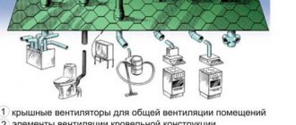
In brick or panel houses, wires can be laid in three ways:
- Inside the ceiling, the route from the switchboard goes vertically, runs along grooves or in a corrugation. Internal ceiling tiles already have channels from where you can run power cables to lamps, switches, and sockets. The wiring runs perpendicularly, without falling horizontally below 15 cm. Each distribution box has an individual automatic switch.
- Under plaster - wires are inserted into pre-drilled holes, fixed, and brought out to consumers. The lines are masked with a layer of plaster, which prevents them from being damaged by voltage fluctuations.
- Under the floor - the line is routed under the floor surface. Channel pipes are laid, which are then filled with solution. Lines for sockets and lighting are masked with a mounting box or pipe.
Open way
Wiring in the baseboard
The open option is used when it is impossible to organize the electrical network in another way. There are several methods:
- On the brackets - for sockets you need copper wires with a cross-section of 2.5 mm2, for lighting - 1.5 mm2. Metal strips are used as staples, fixing them so that the non-flammable part extends 1 cm beyond the line.
- In pipes, corrugated flexible products prevent surface leveling. The diameter of the pipe is equal to the total thickness of the conductors, multiplied by 2. Fastening is done with screws, clips, dowels and nails. Each element is removed from each other by 20-40 cm.
- The boxes contain a metal or plastic cable channel and the baseboard is equipped with a removable lid with a latch. The main difficulty of the work is the correct fastening with screws, dowels or staples. Sockets can be mounted directly onto the box.
Completion
After plastering, painting and wallpaper work, the socket boxes and electrical switchboard will be rubbed and sealed, but it will be easy to feel them and cut the wallpaper along the contour. Having cleared the remaining plaster from the socket boxes, we install sockets, switches, lamps, and a boiler.
Note: it is customary to connect the wires in sockets so that the zero is closer to the window.
Then we assemble the power supply circuit on the terminal blocks in the VShch, but we do not connect the input from the meter yet. EACH BRANCH SHOULD BE CHECKED FOR SHORT CIRCUIT WITH A SHORT CIRCUIT TESTER BEFORE ENTERING IT INTO THE TERMINAL BAR! Now we power the apartment for a short time and use the indicator to find the phase and zero coming from the meter.
We remove the power, connect phase and neutral wires of the corresponding colors to the terminal blocks. AGAIN CHECK FOR SCROTS with the circuit breakers turned on, turn off the main circuit breaker, power the apartment, turn on the main circuit breaker. Didn't it "bang"? We check the lights, voltage in the sockets and continue the repairs.