Types of repairs
There is a document RD 34.20.508 “Instructions for the operation of power cable lines.
Part 1. Cable lines with voltage up to 35 kV." It distinguishes such types of repairs of cable lines at 10 kV and other voltages as planned, emergency and urgent. Planned repairs are carried out according to a schedule developed by the energy company. This document is compiled every month and is based on reports from dispatch services, results of measurements, tests, inspections and walk-throughs. Based on the monthly schedules, in turn, an annual plan for major repairs is developed, carried out in the summer.
The need for emergency repair of a 10 kV cable line or other voltage arises when, after it has been disconnected, it becomes impossible to put it back into operation, provided that the backup line is overloaded and does not allow a high-quality supply of energy to consumers. A larger or smaller number of emergency teams immediately leaves for the work site, and then the personnel act in accordance with the instructions of the dispatcher.
Urgent repair of a 10 kV cable is carried out when receivers of category I or the most important category II are disconnected from the backup power supply - provided that receivers of other categories, consuming energy, overload the operating lines and experience limitations. Repairs are carried out within the work shift in accordance with the instructions of the dispatcher.
The progress of soldering from start to finish
In this chapter, we will describe the entire process in detail, taking into account both significant points and seemingly simple, but no less important, subtleties.
What is needed for work
Electrician tools
The set of tools and materials for work is not very large; all this can be easily purchased in specialized stores. The price for all this is small.
We will need:
- A soldering iron with a stand, and do not choose a powerful model with a thick tip, 15-40 W with a tip with a diameter of about 5 mm is enough;
- For solder, you should also not take thick rods; it is convenient to work with wire 2-3 mm thick;
- Rosin - in addition to it, it is advisable to additionally have both liquid flux and a brush for applying it;
- Tweezers;
- Assembly cutters;
- Pliers;
- Knife;
- File for sharpening and straightening the soldering iron tip;
- Sandpaper, file or needle file with a fine notch to remove oxides and enamels.
Advice! Tubular solder with rosin inside is very convenient.
This is a sufficient set - sometimes you can do without some tools, for example, sandpaper or tweezers, but it is advisable to have everything at hand. Additionally, you may need a tester or probe (if you need to connect a cable of several wires that are not marked with different colors).
There may also be a “third hand” problem when you need to hold two wires or a wire and a connector, but the hand is occupied with a soldering iron. To solve this, you can use a clamp or any suitable clamp.
If you need to connect contaminated wires, then you need to additionally use an alcohol-gasoline mixture, gasoline or some other degreasing agent.
Getting the soldering iron ready
Sharpened soldering iron tip
The soldering iron tip must be sharpened at an angle of 45° and have no defects on the surface. We sharpen it, if necessary, remove excess metal until a smooth surface is obtained.
With a new soldering iron, even after sharpening, the tip becomes tinned. To do this, heat it, dip it in rosin and then touch the solder so that it covers the entire surface of the beveled working area.
Soldering wires
connecting wires by soldering: an example of high-quality work
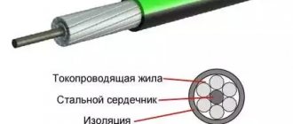
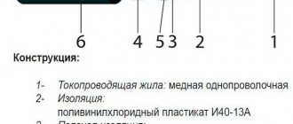
Soldering wires is carried out in several operations, and they depend on their type and insulation. In addition, we are only talking about copper or brass conductors; if they are aluminum, then a soldering iron will not help us (although this can be done with special fluxes) - they are connected with twists or special clamps (see Terminal blocks for connecting wires).
The thickness does not affect the sequence of operations; soldering a thick wire is no different, except that if the diameter is excessively large, it will not warm up. In this case, you just need to take a more powerful soldering iron.
Attention! According to the current operating rules for electrical installations (PEU) and GOST, soldering of copper wires on power, grounding and neutral lines of electrical equipment is prohibited. In an emergency, they can become very hot and the solder will drain. Special clamps are used for connection.
If we solder single-core wires without insulation, we need:
- Remove oxides from the surface - we do this with sandpaper, a fine file or just a knife. You can also pull the wire between the jaws of the nippers several times, turning to clean the entire surface but without squeezing the handles too hard so as not to bite. We do not clean the entire wire, but only the section that we will connect.
- Cover the surface with flux - heat the wire, pressing it against the rosin, it should be completely covered with it. You can also apply liquid flux with a brush.
- Tin - take a little (no need to be greedy) solder on the tip (it should not be a drop, but a small dome, up to 1 mm high, on the working surface of the tip). Then, we touch the soldering iron to the wire and heat it. The solder should cover the surface itself, there is no need to make rubbing movements, just heat it up. If you need to tin a long length of wire, then touch it in several places.
- We connect the wires together , not end-to-end, but lay them parallel to each other for a length of at least 15-20 diameters (this will ensure the mechanical strength of the connection). Better yet, twist the wires.
- Cover the surface with flux again.
- We solder, just like when tinning, we take a little solder and simply warm up the connected wires. It is important that during the process and for some time after the soldering iron is removed (until the solder cools down), they do not move relative to each other.
In the video you can clearly see how the work is done:
Connection of wire, contact or terminal
All operations are carried out in exactly the same sequence. If the contact cannot be immersed in rosin, we use liquid flux.
Stranded wires
Everything is exactly the same. But if we want to increase reliability, then we do not tin the entire bundle, but fluff it up so that each conductor is tinned separately. Then we intertwine them, twist them and solder them.
Wires in insulation
In order to remove the insulation, they usually use wire cutters or a knife. But it’s more convenient to melt it in a circle with a soldering iron and just pull it off (does not work with heat-resistant insulation). This method eliminates the possibility of accidentally damaging the conductor.
Advice! If the wires are very thin, you can burn the insulation with an open fire (lighter).
Enameled wires
Such wire is usually used for winding transformer coils, etc., but sometimes they can be found under a layer of other insulation. They appear clean in appearance, but are actually covered with a layer of colorless enamel. We remove it in the same way as oxides.
Cables made of several insulated wires
When connecting these wires, you should not solder them all at once, as later it will be difficult to wrap them with electrical tape. We connect all the conductors in turn, after completing the insulation of the previous conductor.
Advice! Instead of electrical tape, it is convenient to use heat-shrinkable tubes (in common parlance, “cambrics”). We cut off a piece and put it on the wire, after soldering, we quickly pull them onto it so that the joint is still warm.
Heat shrink tube insulation
We have discussed soldering technology, but another question often arises - how to connect wires in cables connected to the most common types of connectors. Let's try to reveal it too.
Attention! There are wires in braided shielding. We work with it in the same way as with stranded wire. An awl or pin will help to unravel its section.
How repairs are carried out
Depending on the characteristics of the damage that has occurred, it can be simple or complex. The timing of the work and the prices for repairing a 10 kV cable or other voltage depend on them.
Operations such as restoration of the insulating shell, repair of armor and end seals, and some other work performed by one team within one shift are considered simple.
If, in order to restore the power supply, it is necessary to dismantle large (several tens of meters in length) sections of cable to replace it, the repair is considered complex. Difficulties in its implementation are associated with the presence of turns and intersections with utilities and roads on the cable route, and the need to warm up the soil in the cold season. Complex repairs often require two or more teams, often requiring the use of earthmoving and other equipment.
Equipment of our company’s technical staff
The Electricians-MSK team of electricians has at its disposal all the resources to quickly and efficiently carry out repair work:
- mobile electrical laboratory and vehicles for prompt delivery of teams to customer sites;
- modern equipment for testing, measuring and locating cable damage;
- consumables and kits for installing connecting and cable terminations from leading manufacturers;
- manual and electrified tools necessary for the work.
The team consists of experienced electrical engineers with more than one year of experience in electrical installations.
Cost of repairing a 10 kV cable line
It is determined individually and depends on many factors - the characteristics of the damage that occurred, the depth of the cable route, the types of cables being restored, and others.
We adhere to an affordable pricing policy and carry out 10 kV cable repairs at affordable prices - which means you won’t have to overpay when using our services. Cost of repairing cable lines
| Name of works | Price, rub |
| Repair of 6/10 kV cable. | from 11000 |
| Repair of 0.4 kV cable line. | from 9000 |
| Cable fault detection (< 0.5 km) | 15000 |
| Search for cable damage (0.5-1.5 km) | 17000 |
| Finding cable damage (1.5 > km) | 18000 |
| Cable burning (one damage point) | 12000 |
| Finding a broken cable | 15500 |
| Testing of 380/0.4 kV cable. | from 4000 |
| Testing of 10/6 kV cable line. | from 7000 |
| Technical report of electrical measurements | from 10000 |
| Installation of couplings 3 STP 10 | from 5000 |
| Installation of coupling 4-5 STP 1 | from 4000 |
| Installation of connecting couplings 3Pst10 | from 6000 |
| Installation of connecting couplings 1Pst10 | from 3000 |
| Installation of connecting coupling PSPTp-10 | from 7000 |
| Installation of connecting couplings 1PST-20, 1PST-35 | from 3000 |
| Installation of connecting couplings 1PST-20, 1PST-35 | from 5000 |
| Installation of end couplings 3 KVTp 10, 3 KNTp-10 | from 2500 |
| Installation of end coupling 4-5 KVTp-1, 4-5 KNTp-1 | from 2000 |
| Installation of end couplings 3PKVTp-10, 3PKNTp-10 | from 3000 |
| Installation of end coupling 1PKVTp-10, 1PKNTp-10 | from 2000 |
| Installation of end couplings 1PKVT-20, 1PKNT-20, 1PKVT-35, 1PKNT-35 | from 3000 |
Testing of cable lines and monitoring their condition
Industry regulations - PUE, SNiP and others - contain requirements for testing cable lines. The main goal is to identify defective areas on the highway and deliberately cause their breakdown in order to carry out repairs in advance and prevent an accident in the future (or, conversely, to make sure that there are no defective areas). During testing:
- insulation resistance is checked using a megohmmeter;
- Cable lines are checked by applying increased voltage;
- current distribution along the lines is measured.
When checking the technical condition of cable routes after their repair, the same operations are performed, as well as:
- measurement of resistance of cores and terminations;
- inspection of cable lines for their susceptibility to corrosion, the appearance of which can be accelerated by the properties of soil and groundwater, stray currents and other factors.
Specialists test cable lines and check their technical condition in compliance with all norms and regulations - in particular those related to personnel safety. Temporary grounding systems are mandatory to be used to remove residual charges, staff on duty are posted near work sites to prevent access by unauthorized persons, and other measures are taken.
Why does electrical wiring burn out?
Electrical wiring fails for several reasons, the main ones being:
- Short circuit. Kinks and twisting of the wire lead to a breakdown of the insulation, which causes the bare parts to touch each other and cause a short circuit. Most often this happens with the cord in the plug area.
- Connecting several powerful electrical appliances through a tee leads to overheating of the wires approaching the outlet, resulting in a short circuit and electrical wiring failure.
- Broken wire connections. As a result of mechanical damage, wires break, which can lead to a blackout in the room, and in the worst case, to a fire. This happens especially often during careless repairs, when the integrity of the cable is damaged with a drill or nail. In private homes, the cause may be rodents damaging wires.
Compliance with operating rules will help extend the service life of electrical wiring for as long as possible.