yellow + with battery, red + with ignition switch. orange – to the dimensions/panel backlight (dims the radio backlight), blue – to the antenna amplifier, if any
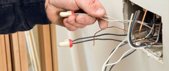
Accordingly, this is the counterpart to the connector that you have on the radio, you will have to buy it. Then everything is very simple: as a rule, the wires on this mating part are already marked: on the insulation it is written what kind of wire it is and where to connect it. The left half of the connector in the figure is the speaker outputs. They will say something like Front Left Positive, Front Left Negative, and so on. Left-Right is oddly enough left-right, Front-Rear is front-rear. It is best to find just such a block, especially if you are not planning a separate amplifier, and the speakers are connected directly to the radio.
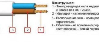
Positive-Negative – it is important to connect them equally to all speakers. The wires of one channel have the same color, only one of the wires is solid color, the second is striped. That is, you need to connect, for example, all solid ones to the left terminals of the speaker, all striped ones to the right ones. If you mix it up, nothing will burn out, but the sound will be worse, because the speakers will work in antiphase; if you connect it correctly, there will be some kind of scene.
Next is the right half of the connector. Everything related to nutrition and management is here. I'll be in order.
Black wire. Big and thick. Weight. No comments. Yellow wire. Also big and fat. Main nutrition. It must be constantly connected to the battery, this is where the radio and its memory are powered. When you disconnect the yellow wire, all settings are reset.
Now about where to hook them. In the case of clinging to the cigarette lighter, or anywhere else to the existing wiring, then you won’t be surprised that “the radio flickers and turns off when I turn it on loudly,” because if you connect it, you’ll get exactly this kind of garbage. Look at the power wires - they are thicker than the others in the block for a reason. Also look at the radio fuse - 10A, no less. At peak loads, especially if it works on its own speakers, and not on the amplifier, it eats up a lot, and if the wire is thin, there is not enough current, and the voltage drops, the radio does not give the speakers the required power, it itself does not have enough power, the speakers wheeze , the radio is trying to turn off, it's complete bullshit.
Therefore: ideally, you take a wire with a cross-section no smaller than that on the block, ideally one and a half to two times thicker, and throw it directly from the battery to the yellow wire. Be sure to hang a fuse near the battery, with a nominal value again one and a half to two times greater than that on the radio (i.e. 15-30A). If you are too lazy to pull the wire from under the hood, cling to the ignition switch.
The power is connected. Further.
Red wire. ACC. Manager. The radio will turn on only if there is +12V on this wire. Made for bourgeois ignition switches, where there is an ACC position - all the electrics are on, but the ignition is not. There is no such provision in Tavria locks, so in principle this wire can be safely screwed in parallel with the yellow one. However, there is one thing - in some radios, when power is supplied to the ACC, the output stages of the amplifiers are turned on, and the current consumed by the radio increases. You can drain the battery very quickly. Is there such a thing in your particular radio - HZ, I protected myself by decoupling with two diodes.
The same is true for the ground wire. You also can’t attach it anywhere.
Connecting the following wires is optional; some may not be present at all.
Blue, white and blue striped - ANT and REMOTE. Control signals for external amplifier and electric retractable antenna. When the radio turns on, +12 appears on them. If you don’t have an amplifier and a retractable antenna, wrap electrical tape around the ends of the wires and leave them alone. One of the wires can be used to control the ACC, so as not to screw it to the power supply. You take two diodes with a current greater than 300 mA, twist the cathodes together, and connect the red wire there. You connect one of the blue wires to one anode, and to the second - the wire from the ignition switch, the one on which +12 appears when the ignition is turned on. As a result, to turn on the radio, you turn on the ignition, turn on the radio, and then the radio will work regardless of whether the ignition is on or not.
Here is a diagram of such a connection:
Orange. ILLUMINATION. Connects to side lights. When you turn on the headlights, some radios can make the backlight of their panel less bright, or turn on the backlight of the panel if the radio is turned off and the headlights are on. This is for convenience, so that in the dark the radio does not distract with bright light and is visible in the dark.
What are the wires used for and where do they go?
Wires for car radios are used to connect to a power source, speakers and amplifier, remove control signals and implement service functions. Thanks to clear identification by color, the likelihood of making a mistake when connecting is reduced, since it is clear which wires go where and what they are needed for.
Orange
The orange wire (ILL) is most often used to control the backlight of the car radio display. It connects to the parking light switch. In this case, several backlight control scenarios are possible. For example, you can make its brightness automatically decrease when the side lights are turned on.
Yellow and red
According to the generally accepted standard, the yellow and red wires are used to connect the positive pole of the power supply to the car radio. Through the first of them, constant power is provided to the device’s microcircuits along with the audio power amplifier and display backlight. When voltage is applied to the yellow cable, all functions of the car radio begin to work. Often, its break is connected to a fuse in a housing that matches the type. The higher the output power of the car radio, the higher the rating of the fuse link.
The red wire, constantly connected directly to the battery, provides continuous power to the volatile memory chip, which stores radio stations recorded by the owner, car radio parameters and the place where listening to music from the media was stopped. The yellow wire is often connected not directly to the on-board network, but through the ignition switch. Thanks to this approach to power supply, the current consumed by the receiver is reduced several times.
Blue and pink
The blue wire is used by some manufacturers to control a motorized antenna. It is supplied with power when the radio mode is turned on. When the radio is turned off, the antenna is automatically retracted, since it contains an additional relay, which is powered directly from the battery. Another purpose of blue is to enable additional functions. For example, the Reverse wire on the radio is used to activate the parking sensors or rear view camera mode.
Pink is used to implement various service functions. One of them is blocking multimedia functions on a 2-din radio with a video player. The control signal is most often supplied from the warning lamp switch under the parking brake lever. As soon as the pink cable is connected to ground, it becomes possible to start the video player or turn on the TV tuner. Otherwise an error message will appear on the display.
Blue - white
The blue-white cable (blue wire with a white stripe) is designed to control the power of the active antenna. It is often marked with a tag marked “Remote”. This cable also supplies a control signal to the car amplifier. The connection can be made either directly to the device or through a special relay.
Color designation
Factory markings include colored shells, alphabetic and digital coding. All insignia and color capsules are applied at the manufacturer.
Other types of designations:
- Color coding is used for wire terminations ; colored stickers and labels are placed. These designations are used by electricians when connecting cables to points of consumption.
- Electronic markers mark engineering and communication routes (power, pipelines, telecommunications).
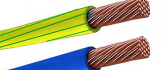
The color of the sheath, specified in the factory, is designed to determine the properties of single-core or stranded wire, the scope of its use in industry, everyday life, and other performance characteristics. This information allows you to intelligently limit use. The marking is applied to the container or to the outer shell.
Phase
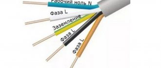
The preferred colors for live cables are brown, black and gray . In a single-phase network, such wires are brown in color. If a single-phase line is obtained as a branch from a working three-phase line, the color of the wire matches the color of the original cable of this circuit.
Features of European markings:
- standardized products are designated har (harmonized);
- digital combinations 07, 05, 03 show the actual voltage 450/750, 300/500, 300/300, respectively;
- the letters r or v indicate the type of insulation (rubber braids or PVC);
- elements U, R, K, F indicate the type of conductor (solid, stranded, soft for general wiring, soft, respectively).
Zero
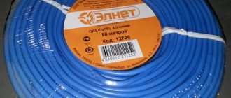
The middle and neutral wires are made with blue braiding . This color cannot be used for conductors other than linear grounded ones.
If non-insulated conductors without a color designation are taken for the neutral line, they are painted in one of the following options:
- paint with blue stripes 20 - 100 mm wide in each connection;
- in accessible areas;
- along the entire length of the wire.
If the neutral cable is combined with protective grounding, it is painted yellow-green, with blue markings (stripes) along its entire length and ends.
Earth
Safety conductors are identified by a green-yellow combination . This combination is only acceptable for a grounding cable.
Coloring rules:
- The combination of yellow and green colors should be of such intensity that for every 1.5 cm of cable length, one of these colors covers the sheath of no less than 30% and no more than 70% of the total area.
- When using cores to protect a different color, they are coated with yellow and green compounds in each block, compartment and in a visible place.
- If you use adhesive tape for marking, it should be of two colors (yellow-green).
If the protective wire can be recognized by its shape and position, it is allowed not to color the wire along its length. It is recommended to mark visible areas and ends with the letters PE or two-color yellow-green stripes. The neutral working and protective cables must not be combined after being inserted into the building.
How to connect a radio
If the instructions or reference label are lost, then before connecting the car radio correctly, you need to check the purpose of the wires using a tester, a suitable current source and a low-power 12-volt light bulb. First, the wires intended for connecting power are recognized.
This procedure also needs to be done if they have different colors than the standard or are not equipped with fuses. For safe detection, you can use a 9-volt battery as a power source. Its negative pole is connected to the car radio body. The positive terminal of the battery is connected in turn to each cable of the car radio. On an old radio, you also need to press the switch or turn the volume control.
At the moment of connection to the cable intended for supplying power, a weak spark will jump between the contacts. If the battery is fully charged, the backlight will light up faintly. On modern radios, the correct connection of the circuit can be confirmed by pressing the Power button. After this, the power will turn on.
Then the wires that give current relative to the minus (radio casing) are determined. To do this, connect a 12 V current source to the previously recognized contacts to supply power. A 10 A fuse must be included in the positive gap in order to increase safety.
A light bulb or tester rated for 15 V or more is connected to the cassette recorder body and alternately to the remaining cords after turning on the device. If the arrow deviates and the light comes on, then the wire is intended to power the antenna or remotely control the amplifier. All cables identified by color must be clearly marked.
You decided to connect the radio yourself, but when you saw the number of wires coming out of it, you were afraid that you couldn’t handle it? In fact, there is nothing wrong with this, and in this article we will figure out how to connect a radio in a car.
What can you encounter if your car radio is not connected correctly?
This is not to say that to properly install a radio, you don’t need to have any skills at all. It is advisable to have at least initial experience in connecting electrical devices, but this is not a prerequisite; following the instructions, a person can complete the installation without any experience. To understand whether everything was done correctly, it is worth monitoring the operation of the radio. A sign of an error will be the presence of the following factors:
- The radio turns off when the volume is increased.
- When you turn off the ignition, the radio settings are lost.
- The radio drains the battery when turned off.
- The audio signal is noticeably distorted, especially when listening at high volumes.
In very rare situations, it is not the person who connected it who is to blame, but the seller who sold the low-quality product. Of course, this option cannot be ruled out, but you will still need to double-check the connection diagram.
Size and types of car radios
Universal radios have a standard size, it can be 1 – DIN (height 5 cm, width 18 cm) and 2 DIN. (height 10 cm, width 18 cm.) If you change the radio from large to small (from 1 – DIN, to 2 – DIN), you will need to buy a special pocket that will cover the missing din. In terms of connection, these radios all have the same connector, its name is ISO or it is also called a Euro connector.
Standard radios are installed on cars from the factory and have a non-standard size; in this case, there are two options for installing the radio. The first is the simplest, you purchase the same standard radio and install it, it fits in size and connects to the standard connectors. But the cost of these radio tape recorders is often inadequate. And if you find a budget option, then with 100% probability it will be from China, which is not particularly famous for its sound quality and reliability.
The second option is to install a “Universal” radio in place of the standard one, but for this you will need an adapter frame, which is an adapter from the standard sizes of the radio to the universal ones, i.e. 1 or 2-DIN. the frame plays a decorative role, covering extra holes.
If your 2 din radio has an LCD display, then you can connect a rear view camera to it, and we discussed in detail how to do this in “this article”
Hint for TOYOTA owners. In most cars of this brand, the standard radio has a size of 10 by 20 cm. In this case, you can look for “Spacers for Toyota radios”, they are 1 cm in size and you can easily install a standard-sized radio, i.e. 2 – DIN, to install 1 – DIN you will still need to buy an additional pocket.
Letter marking
Standard PUE recommendations concern not only color, but also letter markings.
Main types of phase and zero designation:
- Grounding conductor - PE;
- Zero cable - N or 0 (zero);
- Live phase - L.
Multicore cables are designated in sequence from L to LN, for example, L1, L2, L3, etc. The markings of all phase wires are different, for example, purple, gray, brown, red.
Connecting the radio.
There are many cars, and each of them can use its own set of connectors to connect such equipment. Basically, there are three options:
- Option one is the most favorable. You already have a chip in your car to which everything is connected correctly, i.e. All speakers, power wires, antennas are connected to this chip, and everything is connected correctly. This happens but, unfortunately, very rarely. This means that you are lucky, you just connect your brand new radio to this chip, and everything works for you.
- The necessary wires are routed and connected, but the socket on the radio is different from the plug on the car.
- There is no power lead out or it was done incorrectly.
Wire colors in single-phase and three-phase networks
The disadvantage of single-color wiring is the difficulty of finding zero and phase. In order not to regularly use an indicator and a multimeter in single-phase and three-phase lines, a distinction is made by the color of the cables. Such networks are installed in home areas with low load on the electrical network. The list of colors for electrical conductors and their designation by letters are given in the text of GOST 28.763 - 1998.
Single-phase two-cable system:
- Use a two-core conductor with cores of different colors or install two single-core cables.
- Flexible wires with blue (blue) and brown braiding are often used.
- For phase, take a brown color, paint the zero blue.
A three-wire system is a network that uses three wires. In new buildings, such a network is often found. There is a phase neutral conductor in the line, the third is a grounding conductor against electric shock. The color of the first wire is brown, black, the second is blue, and the third is yellow-green.
Three-phase 380V circuits are installed when connecting sockets that have an additional contact for connection to the grounding conductor. Such networks conduct electricity through a three, four or five-core cable. They may have three phase wires and may or may not have a grounding contact. The phase has a braid of brown, black, grey, red, orange or purple.