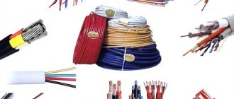
It is impossible to imagine the home of every modern person without electronic devices and household appliances, entangling the home with wires, like vines. Unfortunately, the cable is not permanent and is subject to wear and tear. In addition, if there is a cat or dog in the house, the cords have to be changed much more often. We offer you 8 ways to help protect the wires of household appliances from premature wear.
Please note that repair advice only applies to low-voltage devices, such as smartphone charging cables and cords from game consoles or headphones. It is better to replace damaged wires from powerful devices completely.
Cable protection with vinyl tube
Does your pet love to chew on cables? Luckily, there is an easy way to keep cords safe from sharp teeth. Buy a roll of vinyl tubing, make a lengthwise cut and thread the tubing onto the cable.
ON THE TOPIC: Accessories and care products for iPhone using improvised materials - 11 examples.
Careful use/carrying
Members of the iPhones.ru editorial team have been using Apple devices for years. And they agree on one opinion - to prevent Lightning cables from breaking for months, carefully use and carry each one in your pocket, bag, and so on.
I recommend that you roll the cable in a circle, as shown in the photo above. This will reduce the risk of breaking to a minimum. Avoid getting into mud and so on. And be prepared to be replaced. You can't avoid it.
Cable protection with spiral wrap
If you don't want to deal with vinyl tubing, opt for spiral tubing. The advantage of this method is that you can tie several cords into one bundle at once.
Cable protection with heat shrink tubing
In order to protect the junction of the cable and the connector, you can use heat shrink tubing. Carefully cut two pieces of 3 cm long from the tube. Drop a little silicone glue (there are tubes with adhesive inside) on both ends of the cord at the points of attachment to the connectors and put on the cut pieces of heat-shrinkable tubing. Wipe off any excess glue and hold the heat shrink tube over the flame of a lighter until it shrinks properly. Do not hold the lighter too close, otherwise the cord may melt. If you don't want to deal with fire, use a hair dryer on high setting to dry your hair.
ON THE TOPIC: Baseus, BlitzWolf and CACOY – MFI Lightning cables for iPhone and iPad that are not inferior to the original ones.
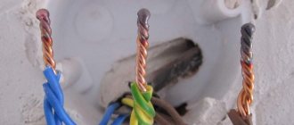
Mechanical damage to electrical wiring
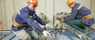
We continue to search for faults in the electrical network. After checking the circuit breaker, we proceed to checking the electrical wiring.
Important! When working with electricity, follow electrician safety precautions. Without work experience, carry out all work only with the power supply turned off.
Mechanical damage to the lighting group wires
The electrical wiring of the apartment lighting group depends on the type of house. In brick houses built in the 50s, 60s and 70s, the apartment lighting is embedded in the floor screed of the upper apartment. In panel houses, the electrical wiring for lighting is laid in the cavities of the floor slabs. Other wiring options are less common. In any case, the electrical wiring of the lighting group starts from the lighting group machine installed in the floor panel and “goes” to the first distribution box of the apartment.
From the first distribution box, the lighting wiring goes in one line to the first room, and the second line to the bathroom and kitchen.
Repairing damaged wires
If the lighting wiring runs along the floor of the upper apartment, repairing such wiring will be associated with problems of neighborly communication. It is likely that the neighbors above were doing repairs and damaged your wiring. Need to check.
Cable protection with a ballpoint pen spring
Some cables, such as those for charging smartphones or those for headphones, wear out faster than others. To prevent premature wear, use a ballpoint pen spring with a button. Stretch the spring slightly and place it over the wire.
You can combine protection using heat shrink tube and spring:
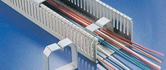
Installation of protective devices
As a rule, protective tapes for cable lines are laid on top of them in a trench channel, and the distance from the outer edge of the covers to the tapes should be 250 mm. Then a layer of sand at least 10 cm thick or earth is poured, but without admixtures of small construction residues and stone particles.
To ensure protection of one cable laid in a trench space, it is enough to lay the tape along its center line; for several cables, the distance from the outermost cable to the edge of the tape should be 50 mm or more. If it is necessary to lay several strips, installation should be done overlapping with a pitch of 50 mm or more.
The device for protecting brick cable lines (layout pattern and quantity) depends on the structure and size of the trench. In addition, brick or concrete reinforced materials will provide reliable fire protection for cables.
Creating new insulation from liquid (rubber) electrical tape
Damaged or worn cable insulation can be repaired using liquid electrical tape such as PlastiDip. Simply mold new insulation around the exposed wire and let it dry.
RELATED: 10 Horribly Designed Everyday Items That Need to Be Reinvented.
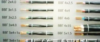
Self-supporting insulated and protected wires for overhead power lines (Part 1)
These technical specifications apply to self-supporting insulated wires for overhead power lines with a nominal voltage of up to 0.6/1 kV inclusive and self-supporting protected wires for overhead power lines with a rated voltage of 20 kV (for networks with voltages of 10.15 and 20 kV) and 35 kV (for networks with voltage 35 kV) with a nominal frequency of 50 Hz, hereinafter referred to as “wires”. The wires in terms of design, technical characteristics and operational properties comply with the national standard of the Russian Federation GOST R 52373-2005. Climatic modification of wires - B, placement categories - 1, 2 and 3 according to GOST 15150-69. Examples of writing a symbol when ordering and in the documentation of another product: - self-supporting insulated wires of the SIP-1 brand with three main conductors with a nominal cross-section of 70 mm2, with a non-insulated load-bearing conductor with a nominal cross-section of 95 mm2, for a rated voltage of 0.6/1 kV:
“Wire SIP-1 3 ½ 70 + 1 ½ 95-0.6/1 TU 16-705.500-2006”; — self-supporting insulated wires of the SIP-2 brand with three main conductors with a nominal cross-section of 50 mm2, with an insulated load-bearing conductor with a nominal cross-section of 70 mm2, with two auxiliary conductors with a nominal cross-section of 16 mm2, for a rated voltage of 0.6/1 kV: “ProvodSIP-2 3S50 + 1S70 + 2S16-0.6/1 TU 16-705.500-2006"; — protected wires of the SIP-3 brand with a conductor nominal cross-section of 120 mm2, for a rated voltage of 20 kV: “Wire SIP-3 1S120-20 TU 16-705.500-2006.”
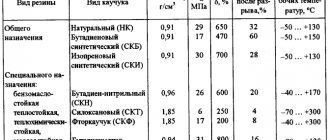
Table 1
| Wire brand | Name | Preferred area of application |
| SIP-1 | Self-supporting wire with aluminum cores, with insulation made of light-stabilized cross-linked polyethylene (PE), with zero load-bearing non-insulated aluminum alloy core | For mains of overhead power lines (OHT) and linear branches from overhead lines in air atmosphere of types I and II according to GOST 15150-69 |
| SIP-2 | The same, with a zero load-bearing core made of aluminum alloy, insulated with light-stabilized cross-linked PE | For overhead power lines and linear branches from overhead lines in the air atmosphere of types II and III according to GOST 15150-69, including on the coasts of seas, salt lakes, in industrial areas and areas of saline sands |
| SIP-3 | Self-supporting protected wire with a conductive core made of aluminum alloy, with protective insulation made of light-stabilized cross-linked PE | For overhead lines with a rated voltage of 10-35 kV in an air atmosphere of types II and III according to GOST 15150-69, including on the coasts of seas, salt lakes, in industrial areas and areas of saline sands |
| SIP-4 | Self-supporting insulated wire without a supporting element, with aluminum conductors, with insulation made of light-stabilized cross-linked PE | For branches from overhead lines to the input and for laying walls of buildings and engineering structures in an air atmosphere of types II and III according to GOST 15150-69 |
Technical requirements.
1.1. Wires must comply with the requirements of GOST R 52373-2005, the requirements of these technical specifications and be produced according to technological documentation approved in the prescribed manner.
1.2. Brands and sizes. 1.2.1. Brands of wires, their names and primary areas of application are given in table. 1. At the customer's request, wires of all brands can be made sealed. In this case, the index “g” is added to the letter designation of the wire brand, for example SIPg-3. OKP codes are given in Appendix A. 1.2.2. The number, nominal cross-section of phase and neutral conductors, calculated outer diameter and weight of wires are given in table. 2.
table 2
| Brand and rated voltage of the wire | Number and nominal cross-section of phase and neutral conductors, pcs. x mm2 | Estimated outer diameter of the wire, mm | Estimated weight of 1 km of wire, kg |
| SIP-1 - 0.6/1 kV |
| 15 | 135 |
| 22 | 270 | |
| 26 | 390 | |
| 30 | 530 | |
| 32 | 685 | |
| 35 | 740 | |
| 37 | 930 | |
| 41 | 990 | |
| 41 | 1190 | |
| 43 | 1255 | |
| 46 | 1480 | |
| 48 | 1715 | |
| 52 | 2330 | |
| 56 | 2895 | |
| SIP-2-0.6/1 kV |
| 24 | 308 |
| 28 | 427 | |
| 27 | 424 | |
| 30 | 512 | |
| 31 | 571 | |
| 32 | 606 | |
| 34 | 727 | |
| 35 | 762 | |
| 36 | 798 | |
| 39 | 973 | |
| 40 | 1010 | |
| 41 | 1087 | |
| 43 | 1240 | |
| 45 | 1319 | |
| 48 | 1553 | |
| 50 | 1787 | |
| 55 | 2403 | |
| 60 | 2968 | |
| SIP-3 - 20 kV |
| 12 | 165 |
| 13 | 215 | |
| 15 | 282 | |
| 16 | 364 | |
| 18 | 445 | |
| 19 | 540 | |
| 21 | 722 | |
| 24 | 950 | |
| SIP-3 - 35 kV |
| 14 | 209 |
| 16 | 263 | |
| 17 | 334 | |
| 19 | 421 | |
| 20 | 518 | |
| 22 | 618 | |
| 24 | 808 | |
| 26 | 1045 | |
| SIP-4 - 0.6/1 kV |
| 15 | 139 |
| 18 | 278 | |
| 17 | 196 | |
| 21 | 392 |
*Until 01/01/2008
The calculated weight and outer diameter of the wires are provided as a reference. 1.2.3. Wires of the SIP-1 and SIP-2 brands with a zero load-bearing conductor cross-section of 50 mm2 or more can be manufactured with 1, 2 or 3 auxiliary conductors. The nominal cross-section of auxiliary conductors for external lighting circuits is 16, 25 or 35 mm2, for control circuits - 1.5; 2.5 or 4 mm2. 1.2.4. The construction length of the wires is agreed upon when ordering.
1.3. Design requirements. 1.3.1. The main and auxiliary conductors for lighting circuits must be twisted from round aluminum wires, have a round shape and be compacted. Auxiliary conductors for control circuits must be single-wire copper and comply with GOST 22483-77. It is allowed to weld aluminum wires if they break or come off during the twisting process. The number of wire connections should not be more than six along the construction length, the distance between adjacent wire connections should be at least 50 m. The tensile strength of aluminum wires before twisting into a core should be at least 120 N/mm2. The number of wires in the main conductor and the outer diameter of the main conductors must correspond to the values indicated in Table 3. 1.3.2. The zero-carrying core and the current-carrying core of the protected wires must be twisted from round wires of aluminum alloy, have a round shape and be sealed. The tensile strength of aluminum alloy wires before twisting into a core must be at least 295 N/mm2, relative elongation at break - at least 4%, elastic modulus - at least 62 103 N/mm2, linear expansion coefficient - no more than 23 10– 6 0С-1. The number of wires in the zero load-bearing core and the current-carrying core of protected wires and their outer diameter must correspond to the values indicated in the table. 4. 1.3.3 The difference between the maximum and minimum diameters of the cores, measured in mutually perpendicular directions of the same section, should not be more than 0.2 mm. 1.3.4 The diameter of the wires, the fill factor of the cross-section of the cores must be indicated in the technological documentation of the manufacturer, approved in the prescribed manner, and must be communicated to the customer upon his request. 1.3.5. The cores of sealed wires must contain a water-blocking element or elements that prevent the migration of moisture along the wire core, in the form of thread, tape or powder.
Table 3
| Nominal cross-section of the main conductor, mm2 | Number of wires in the core, pcs., not less | Outer diameter of the core, mm | Electrical resistance of the conductor to direct current over a length of 1 km, Ohm, no more | |
| min. | Max. | |||
| 16 | 7 | 4,60 | 5,10 | 1,910 |
| 25 | 7 | 5,70 | 6,10 | 1,200 |
| 35 | 7 | 6,70 | 7,10 | 0,868 |
| 50 | 7 | 7,85 | 8,35 | 0,641 |
| 70 | 7 | 9,45 | 9,95 | 0,443 |
| 95 | 7 | 11,10 | 11,70 | 0,320 |
| 95 | 19 | 11,00 | 12,00 | 0,320 |
| 120 | 19 | 12,50 | 13,10 | 0,253 |
| 150 | 19 | 14,00 | 14,50 | 0,206 |
| 185 | 19 | 15,45 | 16,15 | 0,164 |
| 240 | 19 | 17,75 | 18,45 | 0,125 |
Table 4
| Nominal cross-section of the zero load-bearing core and the current-carrying core of protected wires, mm2 | Number of wires in the core, pcs., not less | Outer diameter of the core, mm | Core tensile strength, kN, not less | Electrical resistance of the conductor to direct current over a length of 1 km, Ohm, no more | |
| min. | Max. | ||||
| 25 | 7 | 5,70 | 6,10 | 7,4 | 1,380 |
| 35 | 7 | 6,70 | 7,10 | 10,3 | 0,986 |
| 50 | 7 | 7,85 | 8,35 | 14,2 | 0,720 |
| 54,6 | 7 | 9,20 | 9,60 | 16,6 | 0,630 |
| 70 | 7 | 9,45 | 9,95 | 20,6 | 0,493 |
| 95 | 7 | 11,10 | 11,70 | 27,9 | 0,363 |
| 95 | 19 | 12,20 | 12,90 | 27,9 | 0,363 |
| 120 | 19 | 12,50 | 13,10 | 35,2 | 0,288 |
| 150 | 19 | 13,90 | 14,50 | 43,4 | 0,236 |
| 185 | 19 | 15,45 | 16,15 | 53,5 | 0,188 |
| 240 | 19 | 17,75 | 18,45 | 69,5 | 0,145 |
Table 5
| Nominal cross-section of main, zero load-bearing and auxiliary conductors, mm | Nominal insulation thickness, mm | |
| main cores and zero load-bearing core | auxiliary conductors | |
| 16-35 | 1,3 | 1,3 |
| 50; 54,6 | 1,5 | — |
| 70-150 | 1,7 | — |
| 185; 240 | 1,9 | — |
| 1,5-4 | — | 1,2 |
The method of sealing the wire must be specified in the technological documentation of the manufacturer, approved in the prescribed manner.
Table 6
| Nominal cross-section of main cores, mm2 | Twist pitch, cm, no more |
| 16 | 80 |
| 25 | 80 |
| 35 | 85 |
| 50 | 90 |
| 70 | 100 |
| 95 | 110 |
| 120 | 120 |
| 150 | 130 |
| 185 | 140 |
| 240 | 150 |
1.3.6. The insulation of the main and auxiliary conductors, the insulation (if any) of the zero load-bearing conductor and the protective insulation of protected wires must be extruded (pressed) from light-stabilized cross-linked polyethylene. The insulation must be black. The nominal insulation thickness of the main conductors, zero load-bearing conductor and auxiliary conductors of wires for a voltage of 0.6/1 kV must correspond to that indicated in the table. 5. The nominal thickness of the protective insulation of protected wires for a rated voltage of 20 kV is 2.3 mm, for a rated voltage of 35 kV - 3.5 mm. The lower limit deviation from the nominal insulation thickness is (0.1+0.1 · ?н), where ?н is the nominal insulation thickness, mm. The upper limit deviation is not standardized. 1.3.7. Insulated main and auxiliary conductors must be twisted around the zero load-bearing conductor, if available. Insulated conductors of wires without a zero load-bearing conductor must be twisted together. The twisting of the cores should be in the right direction. The twisting pitch of insulated conductors of wires with a zero load-bearing conductor must correspond to that indicated in the table. 6. The twisting pitch of insulated conductors without a zero load-bearing conductor should be no more than 45 cm.
1.3.8. The materials used for the manufacture of wires must comply with the requirements of GOST R 52373-2005 and the following regulatory and technical documents:
- aluminum wire rod - GOST 13843-78;
- aluminum round wire grade AVL - TU16-705.472-87;
- aluminum alloy wire rod - GOST 20967-75;
- aluminum alloy rod - GOST R 51834-2001;
- aluminum alloy wire - TU 16-705.494-2006, -IEC60104,1987 [1];
- composition of light-stabilized silanol cross-linked polyethylene grades LE 4421/LE 4472 and LE 4423/LE 4472 - according to regulatory documentation f. borealis;
- water blocking materials (powder, threads, tapes) - according to regulatory documentation, “Gega Tapes”;
- copper wire grade MM - TU16-705.492-2005.
It is allowed to use other equivalent materials in agreement with the developer of these technical specifications and when following the procedure established by GOST R 51651-2000. 1.4. Requirements for electrical parameters. 1.4.1. The electrical resistance of the main and auxiliary conductors to direct current, recalculated for a temperature of 20 0C and 1 km of length, corresponding to GOST 22483-77, is given in table. 3. The electrical resistance of the zero load-bearing core and the current-carrying core of protected wires to direct current, recalculated for a temperature of 200C and 1 km of length, must correspond to that indicated in the table. 4. 1.4.2. The specific volumetric resistance of insulation and protective insulation at a long-term permissible heating temperature of current-carrying conductors must be at least 1 Å 1012 Ohm • see 1.4.3. Wires after exposure to water at a temperature of (20 + 10) 0C for at least 10 minutes must withstand an alternating voltage test at a frequency of 50 Hz for at least 5 minutes at the construction length:
- self-supporting insulated - 4 kV;
- protected for rated voltage 20 kV - 6 kV;
- protected for rated voltage 35kV-10kV.
1.4.4. Self-supporting insulated wires must withstand testing on samples with an alternating voltage of 10 kV with a frequency of 50 Hz for at least 30 minutes after exposure in water at a temperature of (20+10) 0C for at least 24 hours. 1.4.5 Protected wires for a rated voltage of 20 kV must withstand on samples tested with a voltage of 24 kV, at a rated voltage of 35-40 kV alternating current with a frequency of 50 Hz for at least 5 minutes. 1.4.6 The breakdown voltage of the protective insulation of protected wires after exposure to water at a temperature of (20+5) 0C for at least 1 hour should be for wires with a rated voltage of 20 kV - at least 24 kV, for wires with a rated voltage of 35 kV - not less than 40 kV alternating current with a frequency of 50 Hz.
Cable protection with Lego
Did you know that the hands of plastic Lego men are great at holding cables? Just stick the figure in the right place using double-sided tape and insert the cord into your hands. This will help keep the cable secure when you are not using it.
ON THE TOPIC: Anker, Aukey, Benks - MFI alternatives to the original Lightning cable for iPhone and iPad.
Real renovation
It should be noted that many preventive measures with heat shrinking are used even when the cable already requires real repairs. That is, in fact, it’s not a good idea to put heat shrink on top of an already torn cable; this is not a very reliable measure, but this type of repair also has a right to exist. However, we are sure that if the insulation is already damaged, more serious repairs are needed and heat shrinking alone will not do. In this situation you will need:
- soldering iron and accompanying materials (rosin, solder)
- wire cutters
- sharp knife
- unnecessary old USB cable (it doesn’t matter which connector is on the other side)
- insulating tape
- heat shrinkage (well, yes, where would we be without it) of two diameters - minimal and 5-6 millimeters
- fire source
As you understand, the work will be serious. However, if you own a soldering iron, everything will be quite simple for you, but if you are just planning to make friends with this wonderful tool, you will have to work a little. So let's get started.
Preparing the USB cable
You can buy a USB cable, but we recommend digging through some old electronics at home. This cable is the most popular, and therefore there is a high probability that the search will be successful. We emphasize that it doesn’t matter at all what happens on the other side, because as soon as the necessary wire is found, we must take the wire cutters and cut off what is there. That is, we should get a cable with a USB connector on one side and a cut wire on the other. Next we will deal with the cut side:
Preparing the iPhone Charging Cable Connector
Good news! It doesn’t matter whether you have an iPhone 5 or an older model - this repair is universal for any cable - both Lightning and the one preceding it.
Connecting the USB cable and the iPhone to the iPhone charging cable
Well, all that remains is to connect the two prepared elements; to do this, you need to solder wires of the corresponding colors to each other - green to green, black to black, etc. But! Before soldering, you must first put heat shrink with a diameter of 5-6 mm on the cable and heat shrink of a minimum diameter on each wire.
When all the wires are soldered, we slide heat shrink over each contact and heat it.
Then, to be sure, we fasten the wires with electrical tape and stretch heat shrink of a larger diameter onto this structure and heat it.
That's all! The renovation is complete.
We tried to describe the process in as much detail as possible, without leaving any dark spots, but if something remains unclear, watch this video -