Power supply diagrams for laptops.
— Scheme of a 70W universal power supply for laptops 12-24V, model SCAC2004, EWAD70W board on an LD7552 chip.
— Power supply circuit 60W 19V 3.42A for laptops, KM60-8M board on a UC3843 chip.
— Diagram of the Delta ADP-36EH power supply for laptops 12V 3A on the DAP6A and DAS001 chip.
— Li Shin LSE0202A2090 90W power supply circuit for laptops 20V 4.5A on the NCP1203 and TSM101 chip, AKKM on the L6561.
— Scheme of the ADP-30JH 30W power supply for laptops 19V 1.58A on the DAP018B and TL431 chip.
— Power supply diagram Delta ADP-40PH ABW
Delta-ADP-40MH-BDA-OUT-20V-2A.pdf - Another version of the Delta ADP-40MH BDA power supply circuit based on DAS01A and DAP8A chips.
— Scheme of the HP Compaq CM-0K065B13-LF 65W power supply for laptops 18.5V 3.5A, model PPP009H-DC359A on UC3842 and LM358 chips.
— Diagram of the power supply NB-90B19-AAA 90W for laptops 19V 4.74A on TEA1750.
— Diagram of the LiteOn PA-1121-04CP power supply on the LTA702 chip.
— Diagram of the Delta ADP-40MH BDA power supply (Part No: S93-0408120-D04) on the DAS01A, DAP008ADR2G chip.
— Circuit diagram of the LiteOn 19V 4.74A power supply on LTA301P, 103AI, PFC on TDA4863G/FAN7530/L6561D/L6562D chips.
— Power supply diagram Delta ADP-90SB BB AC:110-240v DC:19V 4.7A on a DAP6A, DSA001 or TSM103A chip
Delta-ADP-90FB-EK-rev.01.pdf - Diagram of power supplies Delta ADP-90FB AC:100-240v DC:19V 4.74A on the L6561D013TR, DAP002TR and DAS01A chip.
PA-1211-1.pdf - Diagram of the LiteOn PA-1211-1 power supply for LM339N, L6561, UC3845BN, LM358N.
Li-Shin-LSE0202A2090.pdf - Scheme of power supplies Li Shin LSE0202A2090 AC:100-240v DC:20V 4.5A 90W on L6561, NCP1203-60 and TSM101 chips.
GEMBIRD-model-NPA-AC1.pdf - Scheme of the universal power supply Gembird NPA-AC1 AC:100-240v DC:15V/16V/18V/19V/19.5V/20V 4.5A 90W on an LD7575 chip and an MDF9N60 field-effect transistor.
ADP-60DP-19V-3.16A.pdf - Diagram of power supplies Delta ADP-60DP AC:100-240v DC:19V 3.16A on the TSM103W (aka M103A) and I6561D chip.
— Diagram of power supplies Delta ADP-40PH BB AC:100-240v DC:19V 2.1A on a DAP018ADR2G chip and a field-effect transistor STP6NK60ZFP.
— Power supply diagram Asus SADP-65KB B AC:100-240v DC:19V 3.42A on the DAP006 (DAP6A or NCP1200) and DAS001 (TSM103AI) chip.
— Power supply diagram Asus PA-1900-36 AC:100-240v DC:19V 4.74A on the LTA804N and LTA806N chip.
— Power supply diagram Asus ADP-90CD DB AC:100-240v DC:19V 4.74A on the DAP013D chip and 11N65C3 field unit.
PA-1211-1.pdf - Power supply diagram of Asus ADP-90SB BB AC:100-240v DC:19V 4.74A on the DAP006 (aka DAP6A) and DAS001 (aka TSM103AI) chip.
LiteOn-PA-1900-05.pdf - Power supply diagram LiteOn PA-1900/05 AC:100-240v DC:19V 4.74A on LTA301P and 103AI, PFC transistor 2SK3561, power transistor 2SK3569.
LiteOn-PA-1121-04.pdf - Power supply diagram LiteOn PA-1121-04 AC:100-240v DC:19V 6.3A on LTA702, PFC 2SK3934 transistor, SPA11N65C3 power transistor.
Preparing for rework
Before starting work on creating a laboratory unit, you need to decide what voltage and current you need to get from it and select an appropriate power supply from a computer with a controller based on TL494 or its equivalent.
This device will have protection against short circuit, overheating and overload. It will allow you to obtain a continuously adjustable voltage from zero to 25 V, with a current of up to 8-10 A.
Preparing the unit for alteration involves disconnecting the fan, output electrolytic capacitors located on the +12, +5, +3.3 V lines and unnecessary cores of the common harness. The yellow, black, green and network wires should remain on the board.
What parts need to be purchased?
To modify the computer power module, you need to purchase some parts and devices. Radio amateurs may have them in their home laboratory.
Electrolytic capacitors:
- 22 uF/16V;
- the number of other elements and their capacity are the same as those of the parts soldered during the preparation process, but they must withstand a voltage of at least 35-40 V.
You need to purchase additional electrolytic capacitors.
Resistors:
- variable - 22 kOhm and 330 Ohm;
- constant (kOhm) - 47, 15, 10, 1.2 and 3 pcs. 2.7.
Devices:
- voltmeter;
- ammeter - preferably with an internal shunt.
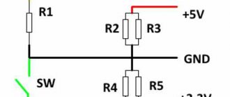
Scheme for finalizing a computer power supply
First you need to remove all unnecessary elements in the TL494 harness. In order not to cut the tracks and not look for parts that need to be removed, you can do it simpler - unsolder and lift 1-4 and 13-16 legs of the microcircuit.
Refinement is carried out by mounted installation according to the diagram:
- Resistors of 2.7, 2.7 and 1.2 kOhm are soldered between the common wire and the 1, 2 and 4 terminals of the controller, respectively.
- The 2nd and 3rd contacts of the TL494 are connected through a resistance of 47 kOhm and a capacitor of 0.01 μF (it is on the board).
- A 22 kOhm regulator is installed between the 1st leg and the +12 V track - it will change the voltage at the power supply output. The positive wire of the voltmeter is also soldered in there.
- The middle terminal of variable resistance 330 Ohms is connected to the 15th output. It will regulate the current.
- 1 of its ends goes to negative, and the 2nd goes through a 10 kOhm resistor to the 13th and 14th legs, soldered together.
- The 16th tap of the microcircuit is connected to the negative side through an ammeter.
- The 14th pin is connected to the 2nd and 4th legs of the TL494 through a 2.7 kOhm resistor and a parallel 22 uF/16V capacitor and 15 kOhm resistance, respectively.
- The devices are connected to the board using a 10-20 cm wire.
- Electrolytic capacitors designed for 35-40 V are soldered in.
- The green wire is connected through a switch to the negative side of the board.
Scheme for redesigning a computer unit.
Voltage
After these alterations, a voltage of +25-30 and +10 V will be established on the +12 and + 5 V lines, respectively. This can be checked by a tester.
After this, install the fan. Since it is connected to a 10-volt line, this will cause a slight reduction in rotation speed.
Typical problems
Most thermopots use a hackneyed electrical circuit, allowing you to identify typical signs of malfunction for units:
- The device does not turn on, there are no signs of life. The serviceability of the power cord, fuses, and thermal switches is checked.
- The water does not boil when pouring, the re-boil button is working. The bottom thermal switch is broken.
- The opposite situation: the re-boil button does not work. Electronic components are to blame. It is necessary to trace the circuit from the power supply to the circuit ground.
- There is no main heating, the auxiliary heating is in order. The heating element has burned out, or the electrical circuit feeding the circuit has been broken.
- The water supply is slow. Two options:
- The additional heating element has burned out, the situation is diagnosed by the absence of standby heating.
- The pump motor is faulty.
Primary aid: when the thermopot does not boil water
The most important thing is to check the settings on the control panel. Perhaps the boiling function is turned off, and the thermopot turns on only in heating mode. Then it turns out that there is no malfunction, which means there is no need to eliminate the broken part. The settings are fine, but the water does not boil - check the temperature sensor and heater. If the elements do not work well, they must be replaced with new ones.
How to disassemble a thermopot:
- Remove the top element – the cover. Then remove the ring securing the inner tank to the housing.
- Remove all fastening elements - screws and bolts.
- Remove the bottom of the thermopot.
In order to disassemble the thermopot, remove the top element and the bottom of the device
For all these manipulations, a screwdriver is useful. To get to the electronic filling of the device, you need to remove all the elements, and only then can you repair the device. Thermal pot can perform many functions, for example, replace a thermal mug. But what good is this if the water there is not boiled - you can’t make tea or coffee.
But, before you disassemble the device, you need to know exactly where everything is attached and how many parts were there before disassembly.
Thermal switches have a boiling function. They are usually located at the bottom of the product or along the walls. To prevent the thermal switch from melting, it is treated with a special solution. To check the element for operation, you need to pull it out and leave it on, screw the wires to it, and place them in the water. With all this, you need to check the resistance. It should not be outside the water; if it increases in water, it means the part is working and the breakdown is not in it. If everything is the other way around, then the thermal switch is faulty.
Schematic diagram of a thermopot
In ancient times, a thermopot would have been called a samovar, now it is affectionately called a potter. It can not only boil water, but also keep it hot, like a thermos. But if your Potter breaks down, you don’t have to call a technician and take it in for repairs. You can do the work yourself. Before using each household appliance, you must read the instructions. Understand how to use the item correctly and what will prolong its use. For example, with a thermopot, according to statistics, the following often break down: the indicator panel, the primary boiling key, the secondary boiling key, the boiling function and the water supply.
All these breakdowns occur due to the influence of high temperature on all elements of the device. For example, the housing that protects the entire device should not heat up when boiling.
These thermopots are very popular: Polaris, Vitek, Elenberg, Scarlett and Alice. The thermopot circuit is simple enough that a non-professional electrician can figure it out. But all the same, a scheme is a scheme, and it is not recommended to get into it without minimal preparation. Therefore, if a thermopot does not boil water at all or does not perform the functions of a thermos, then first you need to examine its circuit and understand the principle of operation.
Before you start repairing the thermopot, you should familiarize yourself with its diagram
Thermopot operation diagram:
- All elements are located under a protective housing;
- The water tank is made of stainless steel;
- Heating coils are installed at the bottom;
- One spiral heats the thermopot, the second maintains the water temperature;
- The thermopot pumps water using a water pump.
The thermopot works as follows: after pouring water into the thermopot itself, the lid closes and the device turns on. One spiral begins to boil water. The thermal fuse turns off the product as soon as the water reaches the desired temperature. The water cools down to the desired temperature set by the user. The temperature itself is maintained by a second heating element. Thermal fuse is recommended to use Sheng Ping SPF 139 reusable. Therefore, if a thermopot breaks down, you will have to completely disassemble it, remove the cover with the button, check the heating element and determine why it broke.
Products from different manufacturers have their own characteristics. For example, the Vitek device has a special button for drawing water into a cup. This button is also called a pump or pump. With its help, you can draw hot water into a cup without getting burned. The circuit board for the Vitek thermopot is called RSP22, it is available and easy to make in special services.
Types of devices
Power supplies can be divided into stabilized and uninterruptible (can operate without electricity).
According to the classification there are:
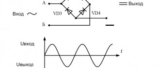
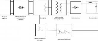
Pulse (have an inverter system that converts alternating current into direct voltage). This device converts alternating voltage into high-frequency voltage at the input.
In order to transform high frequency currents, small electromagnetic coils are needed. All this can be easily placed in a small compact case.
How to make a transformer with your own hands - step-by-step instructions, diagram, drawings, list of materials + photo of a finished homemade transformerWhich hidden wiring detector is better? TOP 10 best manufacturers with photos and descriptions
Technological maps in construction - what is it?
Transformer (have a special rectifier, step-down transformer). Thanks to this device, you can reduce pulsation and vibrations during operation.
Replacing the pump if the thermopot does not pump water
It happens that the thermopot works, boils, heats and keeps the water warm as long as necessary, but it is impossible to pour water - the valve is broken and water supply is impossible. And it’s not at all clear which option is better: a broken heater or a supply function. Such a breakdown indicates a malfunction of the pump (pump) for pumping water into the mug. Then it is necessary to disassemble the machine and examine the suspicious element.
How to get to the pump:
- After removing the metal casing, disconnect the tubes from the pump. If you find scale on the wires, you need to get rid of it.
- Disconnect the pump itself from the tank and housing, while trying not to lose all the small parts.
- As soon as the pump and the electric motor are disconnected, remove all scale that interferes with the proper operation of the device.
If the thermopot does not pump water, then it is necessary to replace the pump
Like any household appliance, a thermopot needs care and maintenance. You can descale it at home using citric acid, acetic acid and baking soda. The thermopot should be cleaned immediately, as soon as the first scale appears. If the product begins to make suspicious sounds, then cleaning is all the more necessary. This is the first signal for help.
If after all these manipulations there is no water supply, then you need to change the pump itself - buy a new one. There is no point in restoring a damaged pump.
Cleaning with soda and acid is carried out in accordance with the size of the product itself. You can also use special cleaning products, just carefully study the composition. Citric acid has its drawbacks - sometimes it is not enough for one kettle. But after boiling water with citric acid, it is important to then wipe the kettle with a soft cloth. There is no smell after boiling, you can combine it with vinegar. Acetic acid removes scale instantly, but it is very difficult to get rid of the aroma afterwards. It requires several boils after and cleaning with a special product, so it is better to clean with a mixture of citric acid and vinegar.