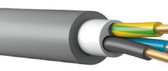
Before purchasing electrical installations, wires, and also if you are going to carry out repair work in the apartment, study carefully how to determine where the wire is zero, phase, grounding and what color these wires are. Color marking of conductor insulation is important so as not to confuse the wires by mistake and to make installation correctly and quickly. Without experience in this field, when you get down to business, you will immediately have many questions: what color of wire needs to be connected to a particular cable core, where is the phase and where is the zero in the socket. We will answer these and other questions for you.
Color marking of the outer braid of current-carrying conductors is regulated by the provisions of technical standards. They are prescribed in the following regulatory codes:
What color indicates phase and zero?
It is recommended to paint conductors of DC circuits as follows:
- positive pole – red (brown insulation color is recommended);
- negative pole – blue (gray color is recommended);
- the grounding conductor in a three-wire DC circuit is blue (since 2009, blue is recommended).
The polarity of the wires can be determined more easily by color. Cool colors are the negative terminal, warm colors are the positive terminal. If there are taps in a three-wire DC electrical circuit, then the outgoing lines should be the same color as the supply lines. Whatever color the plus and minus wires were painted, you need to mark them with an alphanumeric marker.
Expert opinion
Viktor Pavlovich Strebizh, lighting and electrical expert
Any questions ask me, I will help!
An important note regarding the color marking of electrical wires, which, as I have seen more than once, is very often violated. If there is something you don’t understand, write to me!
Color marking according to PUE and GOST (wire colors)
The colors of wires in electrics are regulated by regulatory documents (PUE and GOST R 50462-2009).
According to the rules for the technical operation of electrical installations, each wire of the electrical wiring must be connected to a source of electricity in accordance with the symbol of the wires. All phases have their own color designations, that is, each wire has individual wire colors. When the cable contains braided cores of the same color, a letter designation should be placed at the outputs of each wire. The electrical distribution panel to which the power cable is connected is marked in a similar way.
Which wire is better to use for wiring in an apartment. Review article.
The PUE rules for marking electrical wiring stipulate the following:
- When installing an electrical panel, it is assigned an identification name, or a serial number, which is entered into the general layout of the building's electrical network. The exception is when in an apartment building electrical panels are located individually in each apartment.
- A table is attached to the inside of the panel surface, which indicates all the consumers that are connected to this switchgear.
- After installing the panel and connecting the entire electrical distribution system, the installer must leave the assembly diagram to the consumer or attach it inside the panel room. In order to ensure that in the event of repair and installation work, there is no inconvenience when it is necessary to connect new consumers to the switchboard.
In addition, the PUE and PTEEP contain the following regulations:
- Each cable line has its own name or serial number.
- Cables laid in an open manner must have numbered tags attached.
- Automatic emergency shutdown devices are also marked with the electrical wiring connected to them.
According to the rules of GOST No. 23594, adopted in 1979. and still in force today, all conductor cable cores must be connected according to their color. On the plan diagrams they must be indicated by an individual letter or number. If the braid of the cable cores is one-color, then individual wires at the input and output are marked using tags, seals or multi-colored PVC tubes.
According to the PUE standards, the following colors of current-carrying conductors are allowed:
- red;
- brown;
- black;
- gray; white;
- pink;
- orange;
- turquoise;
- purple.
Color marking in household electrical networks (wire colors)
Wire colors
Wire marking color
Previously, before the introduction of the standard on the use of multi-colored cores, their insulation was black or colored. Such a uniform color significantly complicated installation work, especially if it was necessary to reconnect existing circuits. Now such a problem does not exist and the search for where phase, ground and zero is significantly simplified.
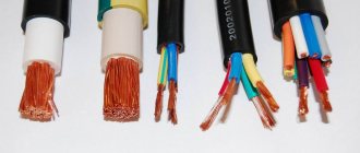
There are strict GOST requirements, according to which any conductor in electrical appliances and installations operating in networks up to 1 kV must have a strictly defined color. Here is a list of the main colors that are found in marking various types of cores:
- blue or cyan color indicates neutral or zero (N) - zero working conductor. On the distribution panel, the zero is attached to a special bus using a terminal or a bolt under a nut that is welded to the body of the box (the panel of the old design),
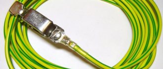
- yellow-green is the protective neutral conductor (PE), “ground”. A wire of this color scheme for grounding is always designed in the form of longitudinal or transverse stripes on the insulation of current-carrying conductors.
- The combined neutral wire (neutral + ground, PEN) is marked in yellow-green with blue marks.
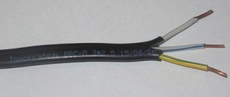
- phase conductors with red, white, black or brown insulation colors represent phase (L) - it can belong to one of the above colors. They are presented in the figure. The phase on the panel always comes to the “machine” or fuse.
The color marking of the working core of a single-phase electrical network, created from a branch from a 3-phase circuit, must necessarily coincide with the color scheme of the original conductor core of the “mother” network.
Standards for color marking of electrical conductors are designed so that the colors of the insulation of current-carrying conductors are never similar, even remotely, to the color of neutral conductors. It happens that unmarked cables are used, then at their ends, at the connection points, appropriate distinctive markings are made using multi-colored electrical tape, cambric or heat shrink.
How to check the correctness of the markings in the apartment?
Relying on color alone is not recommended. Before starting work, it is recommended to check their belongings. A special screwdriver is used for this.
The LED on it lights up when you touch the phase. There will be no problems with a two-core cable, because the second one will be zero. For three-wire, use another tool - a multimeter or tester.
What kind of lighting do you prefer?
Built-in Chandelier
The switch is set on a scale greater than 220V. This indicator or even less should be displayed on the screen, because these are our realities.
To use a multimeter, it is worth considering that when ringing a phase-ground pair, the readings are lower than when ringing a phase-zero pair.
When connecting wires, try to use wires of the same color. Try not to confuse them so as not to face disastrous consequences - injuries or fires.
Marking of wires for 3-phase and DC electrical networks (wire colors)
Wire colors. Coloring phase
In cases where the electrical installation is installed using hard metal busbars, the tires are painted with indelible paint in the following colors:
- yellow - phase A (L1);
- green - phase B (L2);
- red - phase C (L3);
- blue - zero bus;
They look like longitudinal and inclined stripes. Yellow and green stripes - grounding bus. Typically, the color of the phases is maintained throughout the entire device, but not necessarily over the entire surface of the bus. It is allowed to mark the phase designation only at the connection points. You can also duplicate the color on the painted surface with the “ZhZK” symbols for paint of the corresponding colors.
If tires are not accessible for inspection and there is tension on them, it is entirely acceptable not to paint them. The color of phase wires connected to rigid busbars may not coincide with them in color, since there is a difference in the accepted designation systems for flexible conductors and rigid stationary distribution busbars.
Neutral color (wire colors)
He is also a zero working conductor. Its color is specified by GOST standards, so when looking at the installation of a power plant, the question should not arise whether the blue wire is a phase or a zero. According to the standard, blue color and shades of blue are used to indicate neutral (working grounding). The use of other colors to indicate neutral conductors is not permitted. The only acceptable option is to use blue and cyan insulation to indicate the negative pole or midpoint in DC circuits. This color is not used anywhere else.
Grounding color (wire colors)
Wire colors. Coloring phase
Most often in electrical networks, grounding is indicated by a two-color color. Namely, this is a yellow background with a green or black stripe running across it. For combined PEN conductors, the ends are additionally marked with blue marks at the ends. That is, it turns out to be a yellow-blue color. Yellow or green marks can also be added on a general blue background.
When assembling an electrical panel for a 380-volt three-phase network, the following color indication of cable cores is used as standard:
- Red or brown – phase A.
- Black – phase B.
- Gray, white – phase C.
- Blue – zero core.
- Yellow-green – “earth” .
Regulations dictate what color ground wires are in electrical installations. This is a yellow-green wire, the color of which stands out well against the background of the other wires. Any other color cannot be used to indicate the ground wire. Just as it is not allowed to use green-yellow conductors for installing circuits on which voltage is present or can be applied. The listed labeling rules are observed in the countries of the post-Soviet space and in the countries of the European Union. Other states have their own rules. They mark the cores in a different way, which can be seen on imported equipment.
Basic wire colors for marking abroad:
- neutral - white, gray or black;
- protective grounding - yellow or green.
There are even standards for some countries where it is allowed to use bare metal without insulation as protective grounding. Grounding wires are switched on prefabricated non-insulated terminals and connect to each other all metal parts of the structure that do not have reliable electrical contact with each other.
General concepts about the device
Car receivers are divided into two types depending on the method of their installation:
- Stationary - suitable for certain car brands due to their original shape and non-standard size. Such models are built into the car at the assembly stage. For example, such a model is the standard radio on the Chevrolet Cruze DWGM1001 or the Subaru Clarion model installed on the Subaru Impreza.
- Built-in - universal receivers, most have a removable front panel to protect against theft. An example of such models are Pioneer players.


