Radio stations
Radio modems
GSM modems
Antennas
Power supplies and converters
Information
(495) 220-95-14 [email protected]
Explanation of SIP marking:
- C - self-supporting;
- I - isolated;
- P - wire.
The letter at the end of the marking means:
- “A” – neutral core with insulation
- “N” – current-carrying conductors are made of aluminum alloy
- “T” – insulation resistant to elevated temperatures +90°C (short-term +120°C)
- “G” – sealed (moisture will not spread along the wire more than 3 meters from damage to the insulation)
In the marking of a SIP wire, a dash sign indicates the rated voltage for which the wire is intended. Sometimes two values can be indicated here separated by a slash. For example, 0.6/1. This means that the wire is designed for voltages of 660 or 1000V.
And the last thing in the marking is the technical condition according to which the wire is made. Usually this is a set of numbers after the abbreviation TU.
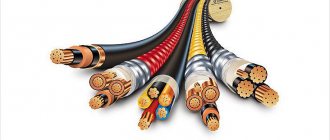
Cable marking, in addition to designating a specific group, also necessarily includes the wire cross-section, date of manufacture, batch number and additional information from the manufacturer.
Peculiarities
SIP is a self-supporting insulated wire, used for power supply in power networks. The SIP electric cable is used in a network with voltage: SIP-1, SIP-2, SIP-4 and SIP-5 are designed for a rated voltage of up to 1 kV, SIP-3 up to 35 kV.
Most SIP wires produced in Russia are color-coded in accordance with the PUE (Electrical Installation Rules) and the new GOST 50462-2009. The insulation of phase conductors and the supporting neutral conductor is made of thermoplastic polyethylene or silanol-cross-linked (light-stabilized) polyethylene, which can withstand temperatures of about 80-90°C for a long time
The technical characteristics of the SIP cable are regulated by GOST R 52373-2005 / GOST 31946-2012 / TU 16-705.500-2006, according to which self-supporting insulated wires include products for overhead lines with voltages up to 0.6/1 kV inclusive, and - protected wires, products for the same lines, but with voltage up to 10 kV; from 10 to 20 kV; 20 kV and 35 kV. There are different types of SIP wire. Most often, SIP type cables are classified by cross-section: 4x16, 2x16, 4x50, 4x25, 4x35, etc. Also, the brand of wire is divided according to the type of core insulation and technical characteristics:
- SIPT-1, also known as SIP-1 - except for the zero core, all the rest are insulated with special polyethylene. SIP-1 is produced for 380 V networks. This is a four-wire cable made of aluminum or aluminum alloy, three cores are covered with light-resistant polyethylene, resistant to ultraviolet radiation, and the fourth without braid with a steel core acts as a carrier and neutral.
- SIPT-2 and SIPT-1A - all threads are isolated;
- SIP-2 - all cores (except for the zero wire) are insulated with cross-linked polyethylene;
- SIP-2A - all conductors, including neutral, are covered with a layer of cross-linked polyethylene;
- SIP-3 - a wire consisting of one conductive core, made of a dense alloy or steel-aluminum wire structure, the insulating layer is made of cross-linked light-stabilized polyethylene. SIP-3 is used for transmitting electrical energy with voltages up to 20 kV;
- SIP-4 - all four cores are insulated with thermoplastic polyethylene, but there is no separate load-bearing core. When laying and tensioning the line, all conductors carry the load, i.e. fastening is carried out immediately for all conductors;
- SIP-5 - does not have a separate load-bearing core, the rest are covered with a sheath of cross-linked (light-stabilized) polyethylene, the number of cores is two or more. They are used mainly in enterprises or for extending electrical networks in the city or between populated areas. It consists of insulated strands coated with polyethylene, where each strand is wrapped in a separate sheath. Types of wire SIP-4 and SIP-5 do not have a supporting zero core and can consist of two or more threads (most often 2 or 3).
Electrical cable made in Russia
Since the end of the twentieth century, domestic industry (and Sevkabel) has shown the first electrically conductive products. In a short period of time, SIP wire has become popular both in everyday life and in production. This was facilitated by its technical operating parameters.
General view of the wire
Experts say that the cost of this wire is generally 25% more than the cost of producing wires without an insulated coating, but the strength of SIP is 70% higher. The Russian government has adopted a program under which enterprises of RAO UES of Russia are transferred to power supply through the operation of self-supporting insulated wires, overhead or otherwise.
This type of cable takes first place when it is necessary to distribute or transform electrical energy. In networks up to 1000 volts (household consumers), SIP grades 1 or 5 are used; for electricity transformation lines up to 20 kV, SIP grade 3 is used. In the territory of the Russian Federation, SIP wire is used for transformation and branches of electrical energy, connecting electricity consumption facilities.
Application of SIP wire:
SIP-1 For mains of overhead power lines (OHT) and linear branches from OHL for rated voltage up to 0.6/1 kV inclusive, with a nominal frequency of 50 Hz in an air atmosphere of types I and II according to GOST 15150.
SIP-2 For mains of overhead power lines (OHT) and linear branches from OHL for rated voltage up to 0.6/1 kV inclusive with a rated frequency of 50 Hz in an air atmosphere of types II and III according to GOST 15150, including on the coasts of seas, salty lakes, industrial areas and areas of saline sands.
SIP-3 – For overhead power lines with a rated voltage of 20 kV (for networks with voltages of 10, 15, 20 kV) and 35 kV (for networks with 35 kV) with a nominal frequency of 50 Hz in air atmosphere II and III according to GOST 15150, including including on the coasts of seas, salt lakes, in industrial areas and areas of saline sands.
SIP-4 Designed for branches from overhead lines to the input and for laying along the walls of buildings and engineering structures for rated voltage up to 0.6/1 kV inclusive, with a nominal frequency of 50 Hz in air atmosphere II and III according to GOST 15150.
Operation and installation
As noted, the advantages of SIP include:
- The use of polyethylene as an insulating material reduces the negative and aggressive effects of the environment. Ability to work in a wide climatic range.
- No problems with commercial electricity metering.
- In the presence of a supporting wire, the mechanical impact on the current-carrying conductors is reduced. The likelihood of wire breakage is greatly reduced.
- Ensuring the safety of civilians during operation.
- High fire safety.
- High reliability of uninterrupted power supply when conductors become jammed or come into contact with foreign objects and equipment.
- Quick and easy installation, because there is no need for traverses or additional insulators. Wires can be laid along the facades of buildings.
- Installation and purchase costs quickly pay off.
Installation stages
- Clearing the area to facilitate installation, assembly and installation of overhead power line supports.
- Delivery of drums with wires and winches on a cable and roller fittings to the destination.
- When crossing overhead lines of various buildings and structures, protective structures are installed.
- Using fastening fittings to enter wires into buildings.
Mechanical characteristics of SIP wire
| Brand and rated voltage of the wire | Nominal outer diameter, mm | Estimated outer diameter of the wire, mm" | Estimated weight of 1 km of wire, kg |
| SIP-1-0.6/1 | 1×16+1×25 | 15 | 135 |
| 3×16+1×25 | 22 | 270 | |
| 3×25+1x35 | 26 | 390 | |
| 3×35+1×50 | 30 | 530 | |
| 3×50+1×50 | 32 | 685 | |
| 3×50+1×70 | 35 | 740 | |
| 3×70+1×70 | 37 | 930 | |
| 3×70+1×95 | 41 | 990 | |
| 3×95+1×70 | 41 | 1190 | |
| 3×95+1×95 | 43 | 1255 | |
| 3×120+1×95 | 46 | 1480 | |
| 3x150+1x95 | 48 | 1715 | |
| 3×185+1×95 | 52 | 2330 | |
| 3×240+1×95 | 56 | 2895 | |
| SIP-2-0.6/1 | 3×16+1×25 | 24 | 308 |
| 3×16+1×54.6 | 28 | 427 | |
| 3×25+1×35 | 27 | 424 | |
| 3x25+1x54.6 | 30 | 512 | |
| 3×35+1×50 | 31 | 571 | |
| 3×35+1×54.6 | 32 | 606 | |
| 3×50+1×50 | 34 | 727 | |
| 3×50+1×54.6 | 35 | 762 | |
| 3×50+1×70 | 36 | 798 | |
| 3×70+1×54.6 | 39 | 973 | |
| 3×70+1×70 | 40 | 1010 | |
| 3×70+1×95 | 41 | 1087 | |
| 3×95+1×70 | 43 | 1240 | |
| 3×95+1×95 | 45 | 1319 | |
| 3×120+1×95 | 48 | 1553 | |
| 3×150+1×95 | 50 | 1787 | |
| 3×185+1×95 | 55 | 2403 | |
| 3×240+1×95 | 60 | 2968 | |
| SIP-3 -20 | 1×35 | 12 | 165 |
| 1×50 | 13 | 215 | |
| 1×70 | 15 | 282 | |
| 1×95 | 16 | 364 | |
| 1×120 | 18 | 445 | |
| 1×150 | 19 | 540 | |
| 1×185 | 21 | 722 | |
| 1×240 | 24 | 950 | |
| SIP-3-35 | 1×35 | 14 | 209 |
| 1×50 | 16 | 263 | |
| 1×70 | 17 | 334 | |
| 1×95 | 19 | 421 | |
| 1×120 | 20 | 518 | |
| 1×150 | 22 | 618 | |
| 1×185 | 24 | 808 | |
| 1×240 | 26 | 1045 | |
| SIP -4 0.6/1 kV | 2x16 | 15 | 139 |
| 4x16 | 18 | 278 | |
| 2x25 | 17 | 196 | |
| 4x25 | 21 | 392 |
Parameters of wires of brands SAPt, SAPssh, SASPt, SASPssh
| Nominal core cross-section, mm2 | Insulation thickness, mm | Outer diameter of core according to insulation, mm | Electrical resistance of the conductor to direct current over a length of 1 km, Ohm, no more | ||
| minimum | nominal | minimum | maximum | ||
| 10 | 1,0 | 1,2 | 5,7 | 6,5 | 3,08 |
| 16 | 1,0 | 1,2 | 6,7 | 7,5 | 1,91 |
| 25 | 1,2 | 1,4 | 8,3 | 9,1 | 1,20 |
| 35 | 1,4 | 1,6 | 9,7 | 10,6 | 0,87 |
| 50 | 1,4 | 1,6 | 11,1 | 12,0 | 0,64 |
| 70 | 1,6 | 1,8 | 12,9 | 13,8 | 0,44 |
| 95 | 1,6 | 1,8 | 14,7 | 15,7 | 0,32 |
| 120 | 1,8 | 2,0 | 15,7 | 16,7 | 0,25 |
Permissible current loads of insulated wires for overhead transmission lines (SIP)
Nominal cross-section of main cores, mm 2
Permissible load current, A, no more
Permissible one-second short circuit current, kA, no more
To organize power power lines, overhead lighting lines, as well as to create a branch from the main electrical line to the entrance to residential premises in a temperate or cold climate zone, self-supporting insulating wires or SIPs are used. They are designed to operate with a voltage of 600/1000V inclusive and a nominal frequency of 50Hz. There are cables designed for voltages of 20 kV and 35 kV.
Decoding and purpose
The abbreviation hides the cable design. It is deciphered as follows: insulated power wire (SIP). It is used for laying:
- overhead lines of trunk networks;
- linear branches;
- distribution inputs to the consumer.
The wire is allowed to be placed on the walls of the facade, but it is prohibited to bring it into the room. New cable modifications marked NG, made according to technical specifications (TU), are allowed by the manufacturer to be used for an intra-house network.
The new generation cable has distinctive features:
- If the wires accidentally overlap, a voltage surge and short circuit are impossible.
- No snow sticking.
- It is completely safe for humans or animals to touch the wire.
- The cross section can be selected to suit any performance needs.
- The cable, SIP, mounted in the distribution unit eliminates the possibility of unauthorized insertion.
Types of SIP
According to GOST 31946-2012 “Self-supporting insulated and protected wires for overhead power lines,” there are several types of self-supporting insulated wires, each of which has its own design features.
SIP wires are produced by industry according to the description given in the technical specifications.
Read also: Basic parameters of a centrifugal pump
SIP cable design
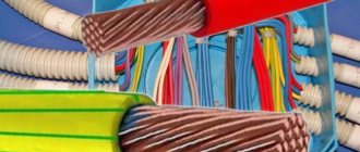
All cables consist of cores (conductors) twisted into a bundle. There are three types:
- Zero – can serve as a neutral, protective or protective-neutral conductor. Made with a cross section from 25mm2 to 95mm2;
- Main or phase - designed to transmit electric current to the consumer. Products are produced with quantities from 2 to 4 cores. Their cross-section can range from 16mm2 to 240mm2;
- Auxiliary or lighting – used to connect lighting, measuring and relay devices.
The phase conductor, like the neutral conductor, consists of aluminum wires that are twisted into a bundle around the core. For the phase core, the core is made of aluminum, and for the zero core, it is made of steel.
There are products without a zero core. They are lighter and have a smaller cross-section.
Lighting, phase and neutral conductors must be tightly twisted from rounded aluminum wires and have a rounded shape. Auxiliary conductors intended for control circuits are made of single-wire copper wire.
Phase conductors are isolated from each other. Depending on the design, the zero phase may or may not be covered with insulation. Light-stabilized silanol cross-linked polyethylene and thermoplastic PET, which has stable lighting performance, are used as insulators.
Light-stabilized silanol cross-linked polyethylene has excellent resistance to moisture and ultraviolet rays. This PET has a wide-cellular three-dimensional molecular structure, which is formed due to cross-links between molecules.
Thanks to this, a durable dielectric is obtained, resistant to mechanical damage, which can withstand high (up to 90°C) and low temperatures. For a short time (within 5s) it can withstand temperatures up to 250°C.
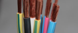
For each core, according to the Electrical Installation Rules, its own color marking is used.
Attention! The neutral support wire is usually marked in blue.
Types of cables
Depending on the design and purpose, the following types of self-supporting insulating wires are distinguished:
- with uninsulated neutral core;
- with insulated neutral core;
- without zero load-bearing core.
The first type is also called “naked”. This includes cable SIP 1.
The second option has an insulated neutral wire. This type includes wires of the SIP 2 brand.
The following types do not include a neutral wire. These include classes SIP 3 and SIP 4.
SIP 3 is a single-core cable with a steel core with protective insulation. SIP 4 does not have a load-bearing element.
Also, at the customer's request, sealed cables can be produced. In this case, the symbol “g” is added to the abbreviation SIP.
If the conductor does not spread fire, then in this case the cable brand has an additional letter “n”.
They also produce brands SIP 1A and SIP 2A.
Cable designation
According to GOST, the marking of conductors should look like:
- The first symbols are “SIP”, indicating the type of conductor;
- The numbers from 1 to 4 are indicated with a hyphen;
- At intervals, numbers are added that indicate the number of each type of core, then through the multiplication sign - their cross-section. Numbers related to each type are separated from each other by a “+” sign;
- A dash indicates the rated voltage of the cable;
- Technical specifications may also be indicated at intervals.
For example, if the marking SIP-2 3×70 + 1×95 + 2×25 - 0.6/1 TU is indicated, then the parameters of the self-supporting insulated wire are as follows:
- designed for organizing overhead power lines;
- has veins:
- 3 main sections 70mm2;
- 1 insulated carrier with a cross-section of 95mm2;
- 2 auxiliary sections 25mm2.
- The cable is designed for voltage 0.6/1 kV.
Permissible short circuit current for wires of the SAPt and SASPt brands, kA
| Cross-section of current-carrying conductor, mm2 | Short circuit duration, s | |
| 1 | 3 | |
| 10 | 0,6 | 0,3 |
| 16 | 1,0 | 0,5 |
| 25 | 1,5 | 0,8 |
| 35 | 2,0 | 1,2 |
| 50 | 3,0 | 1,7 |
| 70 | 4,0 | 2,4 |
| 95 | 5,0 | 2,9 |
| 120 | 5,0 | 2,9 |
Advantages and disadvantages of the product
The advantages of self-supporting insulating wires include:
- Fast and convenient installation and maintenance;
- Electricians installing cables do not need to precisely measure the distance between wires;
- Does not require additional insulators;
- Losses are reduced due to the fact that the reactance in a SIP cable is three times less than in a bare wire;
- Aesthetic appearance;
- It is possible to branch power lines without de-energizing the system. There are special clamps that are used to puncture the insulation, and the clamps themselves fit tightly to the live wires.
The disadvantage of SIP type cable is the large weight of one meter of cable, which entails the need to place supports at a closer distance.
Laying conditions
Laying the wire does not require any special skills. With the help of fittings for installing SIP, almost anyone can cope with this after familiarizing themselves with the rules.
We will provide a superficial overview of the installation of self-supporting insulated wire. On the support, special metal clamps are used to install fastenings for anchors that will hold special clamps. The SIP is wound onto the supports using the pulling method; first, rolling rollers are installed on the posts, with a protective layer of plastic that prevents damage to the insulation of the cable being pulled, and with a leader rope installed in advance, it is stretched, unwinding it from the reel.
During installation, avoid dragging on the ground and tree branches. Using a dynamometer, the permissible line tension is determined. After this, the wire is fixed in the spans. The line is connected and removed using hermetically sealed clamps. Electrical contact is made by piercing the protective layer with spikes. The connection can be made under voltage; the design of the piercing clamp allows this procedure to be carried out safely.
The process of installing SIP wires is discussed in detail in the video below:
https://youtube.com/watch?v=Ahjb2-eAIkk
Technical characteristics of SIP 2 cable
SIP 2 wire is produced with the following technical characteristics:
- the number of conductors can be from 1 to 4;
- the cross section is in the range of 16-120 mm2;
- the zero core is made of aluminum alloy and has a steel core;
- rated voltage – 0.6-1 kV;
- insulation material – light-stabilized silanol cross-linked polyethylene;
- relative humidity of the operating environment – up to 98%;
- the minimum bending radius is 10D, where D is the diameter of the wire;
- installation of the wire is allowed at a temperature of at least -20°C;
Temperature parameters:
- Operating temperature range – -60°С – +50°С. Thanks to these properties, the cable can be used when laying electrical networks in a cold climate zone;
- Heating up to +90°C for 8 hours is allowed;
- Short-term heating up to 130°C is allowed;
- The permissible short circuit temperature is +250°C.
Attention! During operation, heating up to 90°C is possible. It is allowed to be allowed for no more than 8 hours per day, no more than 100 hours per year, and no more than 1000 hours for the entire period of work.
The warranty period is at least 3 years, the service life must be at least 40 years.
Strength characteristics of SIP 2
| Nominal cross-section of zero and main cores, mm2 | Core tensile strength, kN, not less |
| 25 | 7,4 |
| 35 | 10,3 |
| 50 | 14,2 |
| 70 | 20,6 |
| 95 | 27,9 |
| 120 | 35,2 |
| 150 | 43,4 |
| 185 | 53,5 |
| 240 | 69,5 |
Depending on the number of cores and their cross-section, cables have different weights and diameters.
Characteristics of the diameter and weight of SIP 2 wire
| Number and cross-section of cores | Outer diameter of wire, mm | Weight of 1 km of wire, kg |
| 1x16 + 1x25 | 16,4 | 167 |
| 3x16 + 1x25 | 24,1 | 307 |
| 3x25 + 1x35 | 27,1 | 424 |
| 3x35 + 1x50 | 30,8 | 570 |
| 3x50 + 1x50 | 34,1 | 729 |
| 3x50 + 1x70 | 36,1 | 799 |
| 3x70 + 1x70 | 40,0 | 1010 |
| 3x70 + 1x95 | 41,8 | 1086 |
| 3x95 + 1x70 | 44,2 | 1247 |
| 3x95 + 1x95 | 45,9 | 1323 |
| 3x120 + 1x95 | 48,1 | 1545 |
| 3x150 + 1x95 | 50,9 | 1812 |
| 3x185 + 1x95 | 55,0 | 2162 |
| 3x240 + 1x95 | 59,6 | 2652 |
| 4x16 + 1x25 | 24,1 | 377 |
| 4x25 + 1x25 | 27,1 | 522 |
Design parameters of wires of the SAPt, SAPssh, SASPt, SASPssh brands
| Wire brand | Total number of cores | Nominal cross-section of the load-bearing core, mm2 | Conductors | Weight, kg/km | |||
| basic | auxiliary | ||||||
| number and nominal cross-section, mm2 | nominal diameter, mm | nominal cross-section, mm2 | nominal diameter, mm | ||||
| SAPt, SAPssh | 2 | — | 2×10 | 3,8 | — | — | 92 |
| — | 2×16 | 4,8 | — | — | 133 | ||
| SASPt, SASPssh | 4 | 16 | 3×10 | 3,8 | — | — | 181 |
| 25 | 3×16 | 4,8 | — | — | 278 | ||
| 35 | 3×25 | 6,0 | — | — | 399 | ||
| 50 | 3×35 | 7,0 | — | — | 553 | ||
| 70 | 3×50 | 8,4 | — | — | 751 | ||
| 95 | 3×70 | 9,8 | — | — | 1030 | ||
| 95 | 3×95 | 11,6 | — | — | 1247 | ||
| 95 | 3×120 | 13,0 | — | — | 1503 | ||
| SASPt, SASPssh | 5 | 35 | 3×25 | 6,0 | 25 | 6,0 | 501 |
| 50 | 3×35 | 7,0 | 25 | 6,0 | 654 | ||
| 70 | 3×50 | 8,4 | 25 | 6,0 | 853 | ||
| 95 | 3×70 | 9,8 | 25 | 6,0 | 1132 | ||
| 95 | 3×95 | 11,6 | 25 | 6,0 | 1348 | ||
| 95 | 3×120 | 13,0 | 25 | 6,0 | 1605 | ||
| 50 | 3×35 | 7,0 | 35 | 7,0 | 691 | ||
| 70 | 3×50 | 8,4 | 35 | 7,0 | 889 | ||
| 95 | 3×70 | 9,8 | 35 | 7,0 | 1169 | ||
| 95 | 3×95 | 11,6 | 35 | 7,0 | 1385 | ||
| 95 | 3×120 | 13,0 | 35 | 7,0 | 1642 | ||
Video
While browsing the internet for electrical installations, I found a thread on one forum discussing “whether a 4x16 sip can withstand 15 kW.” The question arises because 15 kW 380 volts are allocated for connecting a private house. Well, people are wondering if it’s not enough to lay 16 square meters on a branch from the overhead line? I first looked into the PUE, but for some reason I didn’t find anything there on the topic of SIP power. There is only plate 1.3.29 “Permissible long-term current for non-insulated wires according to GOST 839-80.” And it shows that the maximum permissible current for the cross section is 16 kV. mm. wire type AC, ASKS, ASK outdoors is 111 amperes. Well, at least something to start with.
How many kilowatts can SIP withstand - table:
| SIP section | voltage 380V | voltage 220V |
| SIP 4x16 | 38 kW | 66 kW |
| SIP 4x25 | 50 kW | 85 kW |
| SIP 4x35 | 60 kW | 105 kW |
| SIP 4x50 | 74 kW | 128 kW |
| SIP 4x70 | 91 kW | 158 kW |
| SIP 4x95 | 114 kW | 198 kW |
| SIP 4x120 | 129 kW | 225 kW |
| SIP 4x150 | 144 kW | 250 kW |
| SIP 4x185 | 166 kW | 288 kW |
| SIP 4x240 | 195 kW | 340 kW |
Permissible continuous current for wires of the SAPt and SASPt brands, A
| Conductor cross-section, mm2 | Solar radiation intensity, W/m2 | |||||
| 0 | 600 | 1125 | ||||
| Ambient air temperature, °C | ||||||
| 25 | 40 | 25 | 40 | 25 | 40 | |
| 10 | 75 | 60 | 60 | 40 | 40 | — |
| 16 | 95 | 75 | 70 | 45 | 45 | — |
| 25 | 125 | 100 | 95 | 60 | 55 | — |
| 35 | 150 | 120 | 110 | 65 | 60 | — |
| 50 | 195 | 160 | 140 | 85 | 65 | — |
| 70 | 240 | 195 | 170 | 95 | — | — |
| 95 | 290 | 235 | 200 | BY | — | — |
| 120 | 340 | 275 | 230 | 120 | — | — |
Calculation method
We take plate 10 and from it we find that one core is 16 sq. mm. withstands - 100 amperes. And then the most important thing is how much should this 100A be multiplied by - by 220 or 380? Here we need to look from the point of view of consumers who will be connected to the sip. If this is an ordinary residential building, then there are not so many three-phase appliances (well, the only thing that comes to mind is an induction cooker or electric oven, although they are essentially 220V), if this is some kind of repair shop, then there is already more three-phase equipment (lifts, welding, compressor).
Read also: Adjusting the oil supply to the chainsaw chain
At the beginning of the topic, the question was raised: “will a 4x16 15kW sip handle it?” Therefore, for a private house we multiply 220Vx100A = 22 kW per phase. But don’t forget that we have three phases. And this is already 66 kilowatts
total for a residential building.
Which is a 4-fold margin
relative to the issued technical conditions.
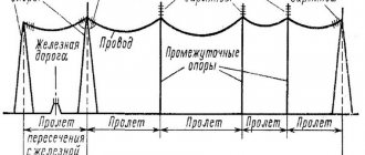
The main purpose of SIP cables is to transmit electricity over overhead lines. The cable is actively used in the removal of electricity from main highways to residential and commercial buildings, and in the construction of lighting networks on the streets of populated areas.
Self-supporting insulated wire (SIP)
SIP design
The phase aluminum wires are coated with a light-stabilizing black insulating coating. The polyethylene coating is highly resistant to moisture and ultraviolet sunlight, which destroy rubber or conventional polymer insulation.
The wires are twisted into a bundle around a zero aluminum core, in the center of which there is a steel wire. The core of the neutral core is the supporting basis of the entire cable. Some designs of SIP cables with a small cross-section and a small number of cores are light in weight, since these types do not have a steel core. SIP stands for self-supporting insulated wire.
Types and structure
Five main types of SIP wires are produced:
- SIP-1 includes three phases, each of which is twisted into a bundle of several aluminum wires around an aluminum alloy core. The wires of the fourth neutral core are twisted around a steel core. The phases are insulated with UV-resistant thermoplastic. On the SIP-1A cable brand, the neutral wire, like the phase conductors, is in an insulated sheath. Such cables can withstand prolonged heating times at 70°C.
Cable design SIP-1, SIP-1A
- SIP-2 and SIP-2A have a similar design to SIP-1 and 1A, the only difference is in the insulating shell. The insulation is “cross-linked polyethylene” - a connection of polyethylene at the molecular level into a network with wide cells with three-dimensional cross-links. This insulation structure is much more resistant to mechanical stress and can withstand lower and higher temperatures during prolonged exposure (up to 90°C). This allows the use of this brand of SIP cable in cold climates under heavy loads. The maximum voltage of transmitted electricity is up to 1 kV.
- SIP-3 is a single-core cable with a steel core, around which wires made of AlMgSi aluminum alloy are twisted. The insulating shell made of “cross-linked polyethylene” allows the use of SIP-3 for the construction of overhead power transmission lines with voltages up to 20 kV. The operating temperature of the cable is 70°C, it can be used for a long time at temperatures ranging from minus 20°C to + 90°C. Such characteristics allow the use of SIP-3 in various climatic conditions: in temperate climates, cold or in the tropics.
Internal structure of the SIP-3 cable
- SIP-4 and SIP-4N do not have a neutral wire with a steel rod; they consist of paired wires. The letter H indicates that the wires are made of aluminum alloy. PVC insulation is resistant to ultraviolet radiation.
Design of self-supporting insulated wire SIP-4
- SIP-5 and SIP-5N - two cores have a similar structure to SIP-4 and SIP-4N, the difference is in the insulating sheath. Cross-linked polyethylene technology allows you to increase the operating time at the maximum permissible temperature by 30 percent. Power lines using SIP-5 are used in cold and temperate climates, transmitting electricity with voltages up to 2.5 kV.
Internal structure of self-supporting insulated wire SIP-5
Depending on the operating conditions and the load of electricity consumed, the brand and cross-section of the SIP cable are selected.
Selection of SIP section
The selection and calculation of the cross-section of SIP wires for connecting various consumer objects is carried out using the classical method. The maximum power consumption of electrical installations is added up, and the current load is calculated using the formula:
— P – total power consumption;
— I – maximum current consumption;
— U – network voltage.
Based on the value of the maximum current, you should select the required cross-section of SIP wires using pre-calculated tables.
Parameters of the most used SIP cables for connecting buildings from the main power lines (SIP-1, SIP-1A, SIP-2, SIP-2A)
| Section in mm and number of cores | Phase resistance in Ohm per 1 km | Maximum permissible phase current with thermoplastic insulation | Maximum permissible phase current with cross-linked polyethylene | Short circuit current in kA for a duration of 1s |
| 1x16+1x25 | 1.91 | 75 | 105 | 1 |
| 2x16 | 1.91 | 75 | 105 | 1 |
| 2x25 | 1.2 | 100 | 135 | 1.6 |
| 3x16 | 1.91 | 70 | 100 | 1 |
| 3x25 | 1.2 | 95 | 130 | 1.6 |
| 3x16+1x25 | 1.91 | 70 | 100 | 1 |
| 3x25+1x35 | 1.2 | 95 | 130 | 1.6 |
| 3x120 +1x95 | 0.25 | 250 | 340 | 5.9 |
| 3x95+1x95 | 0.32 | 220 | 300 | 5.2 |
| 3x95+1x70 | 0.32 | 220 | 300 | 5.2 |
| 3x50+1x95 | 0.44 | 180 | 240 | 4.5 |
| 3x70+1x70 | 0.44 | 180 | 240 | 4.5 |
| 3x50+1x70 | 0.64 | 140 | 195 | 3.2 |
| 3x50+1x50 | 0.64 | 140 | 195 | 3.2 |
| 3x35+1x50 | 0.87 | 115 | 160 | 2.3 |
| 3x25+1x35 | 1.2 | 95 | 130 | 1.6 |
| 3x16+1x25 | 1.91 | 70 | 100 | 1 |
| 4x16+1x25 | 1.91 | 70 | 100 | 1 |
| 4x25+1x35 | 1.2 | 95 | 130 | 1.2 |
When choosing the cross-section and brand of SIP wires, it is important to take into account not only the maximum current load, but also the temperature and the time during which the cable can be operated in extreme conditions. Typically, the allowable duration is between 4000 and 5000 hours.
Maximum temperature for wires
When choosing the brand of SIP cable and its heating cross-section, you must take into account the type of insulation: cross-linked polyethylene or thermoplastic. Taking into account voltage losses, thermal resistance during short circuit, mechanical strength, if one of the parameters is insufficient, a cable with a large cross-section is selected.
When operating a SIP cable, overloads are allowed up to 8 hours a day, 100 hours a year and no more than 1000 hours for the entire period of operation. Most often, SIP-2A is used to connect residential buildings or commercial facilities, this is due to some disadvantages of other cable models:
- on SIP-1 and SIP-2, the neutral conductor is not insulated; if it breaks, there may be an induced potential that is dangerous to humans;
- SIP-1(A), SIP-4 has weak insulation;
- SIP-3 is used only for voltages above 1000V, it is a single wire;
- SIP-4 or SIP-5 do not have a central load-bearing core, so they can only be used over short distances; at long intervals, the cable stretches and sag.
From the above table it can be seen that the SIP-2A cable can have the same or different core cross-sections. Typically, when the cross-section of the phase conductors is 70 sq./mm, the zero conductor for strength is made 95 mm/sq. With a larger cross-section of phases, the carrier phase is not increased; the mechanical strength is quite sufficient. With a uniform distribution of electricity across phases, the zero conductor experiences virtually no electrical and thermal load. For lighting networks, cables with a core cross-section of 16 or 25 sq./mm are usually used.
Permissible long-term current for wires of the SAPSSH and SASPSH brands, A
| Conductor cross-section, mm2 | Solar radiation intensity, W/m2 | |||||
| 0 | 600 | 1125 | ||||
| Ambient air temperature, °C | ||||||
| 25 | 40 | 25 | 40 | 25 | 40 | |
| 10 | 90 | 80 | 80 | 65 | 65 | 50 |
| 16 | 110 | 95 | 95 | 80 | 75 | 55 |
| 25 | 150 | 130 | 125 | 105 | 100 | 70 |
| 35 | 180 | 155 | 150 | 120 | 120 | 80 |
| 50 | 235 | 205 | 195 | 160 | 150 | 100 |
| 70 | 290 | 255 | 240 | 190 | 180 | 115 |
| 95 | 350 | 305 | 280 | 225 | 210 | 125 |
| 120 | 410 | 360 | 330 | 265 | 240 | 140 |
Calculation example
An example of calculating the cross-section of a SIP cable for connecting an object with a total power of electrical appliances of 72 W, at a distance from the main power line of 340 m. Supports for hanging the SIP cable should be placed at intervals of no more than 50 m, this will significantly reduce the mechanical load on the wires. The maximum current for a three-phase circuit should be calculated when all electrical appliances are turned on. Provided that the load is distributed evenly between the phases, one phase will have:
72 kW / 3 = 24 kW.
The maximum current in one phase, taking into account the inductive and capacitive load of electrical appliances (cos fi = 0.95) will be:
24 kW / (230V* 0.95) = 110A.
According to the table, a SIP cable with a cross-section of 25 A is selected, however, given the cable length of 340 m, voltage losses must be taken into account, which should be no more than 5%. For ease of calculation, the cable length is rounded to 350 m:
- in SIP, the resistivity of aluminum is 0.0000000287 ohm/m;
- The wire resistance will be Rpr. = (0.0000000287 / 0.000025) Ohm/m * 350 m = 0.4 Ohm;
- load resistance for 24 kW. Rн = U 2 * cos fi: P = 230 2 * 0.95 / 24 kW = 2.094 Ohm;
- total resistance – Rtotal. = 0.40 Ohm. + 2.094 Ohm. = 2.5 Ohm.
Read also: How to dilute gasoline for a Husqvarna chainsaw
Based on the calculated data, the maximum current in the phase conductor will be:
I = U / R = 230V: 2.5 Om = 92 A
The voltage drop is equal to I max * Rpr. = 93A * 0.4 Ohm = 37V.
37 Volts is 16 percent of the mains voltage U = 230V, which is more than the permissible 5%. According to calculations, a SIP with a cross-section of 95 sq./mm is suitable. The losses with such a wire are 11 V, which is 4.7%. When calculating a single-phase line, the total power is not divided by 3, the cable length is multiplied by 2.