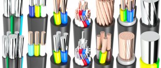
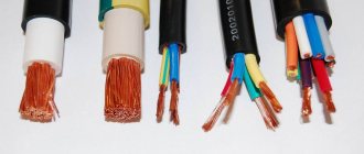
Electrical wiring in a house or cottage serves to transport electricity to various types of electricity consumers: lighting fixtures, heaters, boilers, pumps, televisions, etc. All these devices create comfortable living conditions and have a wide range of power consumption from 10 W (shavers, DVDs) to 5 kW (boilers, electric boilers). The role of electrical wires is very difficult to overestimate. Further comfort and safety during operation depends on the correct choice of wire types for various consumer groups at the design and construction stage. Hundreds of meters of wires for various purposes are hidden in the walls of modern buildings, and they are all different - some are thicker, others are thinner, some have two cores, and some have three or more. Each wire has its own purpose (power wiring, lighting, signal cables, telephone cables, Internet) and is responsible for the operation of a particular electrical appliance. Of the many different types of wires and cables, in this article we will look at electrical wires and cables used in construction to transport electricity. Let's consider their varieties, brands and scope of application. Electrical wiring – consists of wires and cables with their associated fastenings, support and protective structures.
Electrical wires are produced in copper and aluminum. Copper wires have better conductivity than aluminum wires, but are also more expensive.
What is a wire?
A wire is one uninsulated or one or more insulated strands, over which there may be a non-metallic sheath, winding or braid of fibrous materials or wire. Wires can be bare or insulated. Wires can be used for power lines, for the manufacture of electric motor windings, for connections in electronic equipment, etc.
Bare wires do not have any protective or insulated coatings and are mainly used for power lines.
The cores of the insulated wires are covered with PVC, rubber or plastic insulation.
Installation wires - wires for low voltage electrical distribution networks.
Bare wires are those that do not have protective or insulating coatings on top of the conductive cores. Bare wires of the brands PSO, PS, A, AS, etc. are usually used for overhead power lines.
Insulated wires are those in which the current-carrying conductors are covered with insulation, and on top of the insulation there is a braid of cotton yarn or a sheath of rubber, plastic or metal tape. Insulated wires can be either protected or unprotected.
Protected wires are called insulated wires that have a sheath on top of the electrical insulation designed to seal and protect from external climatic influences. These include wires of the brands APRN, PRVD, APRF, etc.
Unprotected are called insulated wires that do not have a protective sheath over the electrical insulation (wires of the APRTO, PRD, APPR, APPV, PPV brands).
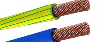
Rules for connecting a stranded conductor
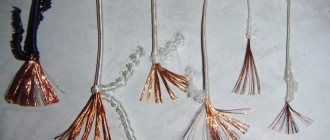
Very often, when laying a multi-core cable or wire, it becomes necessary to connect it to such common elements of the electrical circuit as a circuit breaker, socket, meter, plug, lamp socket, and so on. Most often, copper wires are used, especially in everyday life. The main task is to ensure reliable contact with the clamping bolted connection of these devices and devices, and therefore to make the stranded wire as monolithic and homogeneous as possible. You can perform this procedure in several ways:
- Twist all the thin strands into a tight bundle and, if the cross-section allows, bend it in the opposite direction. This can be done with pliers or by hand, it all depends on the cross-section of the conductor. This method is the simplest and is used in modern wiring only in emergency cases, but it also has a right to exist. It will not be possible to perform this procedure with a large cross-section cable in this way, so it is more suitable for supplying voltage to a plug, socket, or socket of a low-power lighting fixture.
- By tinning the conductor. This method is more effective than the previous one and will ensure reliable contact. Its main disadvantage is that you do not always have a soldering iron at hand, and even electricity for its operation. Tinning can be done either with a straight conductor or with a terminal block bent into a ring along the diameter of the bolt, but before doing this, again, it is necessary to tightly twist all the thin wires. This method can be applied in all cases of connection to electrical appliances, to a machine, socket, etc., if the cross-section allows it.
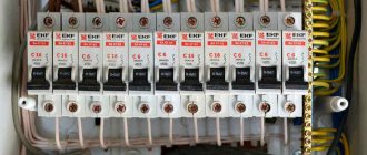
- Tip crimping. The tips allow you to achieve reliable and durable contact without soldering. There are two types of tips: bolt-on and simply sleeved. Depending on the element to be connected, you need to select the appropriate type and appropriate cross-section. With a tip and sleeves you can connect any type of cable, of any cross-section, both stranded and single-core, but for this you will need a special tool that will need to be purchased before carrying out installation work, especially at a professional level. Connecting a stranded wire in this way in the panel, to the terminal block, to the meter not only looks aesthetically pleasing and correct, but also reduces the likelihood of heating at the connection points. The photo below shows NShVI type lugs on stranded wires.
Although tinning is a good method, in practice the cores are often terminated with lugs; this is faster, easier and often more reliable than other methods. However, do not crimp the tips with pliers - the core will simply jump out of them and you will not get a good connection. To do this, it is better to buy crimping pliers with square dies; you can find them for about 1000 rubles.
What is a cable?
A cable is one or more insulated conductors enclosed in a common sealed sheath (lead, aluminum, rubber, plastic), on top of which, depending on the laying and operating conditions, there may be an armor sheath (coating of steel tapes or flat or round wire). Such cables are called armored. Cables without armor are used where there is no possibility of mechanical damage.
According to the area of application, the cables are divided into the following types:
- Power cables are designed for the transmission and distribution of electrical energy in lighting and power electrical installations to create cable lines. They are produced with copper and aluminum conductors with insulation made of paper, PVC, polyethylene, rubber and other materials, and have lead, aluminum, rubber or plastic protective sheaths.
- Control cables are used to power various electrical devices with low voltage signals and create control circuits. They can have copper or aluminum conductors with a cross-section from 0.75 to 10mm2.
- Control cables are used in automation systems and usually have copper conductors, a plastic sheath and a protective shield that protects against mechanical damage and electromagnetic interference.
- RF cables are used to provide communication between radio devices. They have a coaxial design with a central copper core, which has insulation made of polyethylene or polyethylene, on top of the insulation there is an outer conductor and a sheath of PVC or polyethylene.
NON-INSULATED WIRES FOR OVERHEAD POWER LINES AND ELECTRIFIED TRANSPORT
2.1. NOMENCLATURE
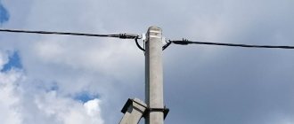
Non-insulated wires for overhead lines are intended for the transmission of electrical energy in overhead electrical networks and electrified transport lines. Under operating conditions, these wires are insulated from the ground and from each other using porcelain, glass and other insulators on which they are suspended. The distance between the wires is selected depending on the transmitted voltage. Split two to four wires are under the same voltage and are suspended on one garland of pendant insulators. The list of brands of bare wires for power lines and contact wires for electrified transport is given in Table. 2.1, and the assortment is in table. 2.2.
Table 2.1. Nomenclature of bare wires
| Brand | OKP code | The wire | GOST, TU |
| Wires for overhead power lines | |||
| A | 3511410100 | Twisted from aluminum AT wires | GOST 839-80 |
| automatic transmission | 3511410200 | The same, but the interwire space, with the exception of the outer surface, is filled with neutral lubricant with increased heat resistance | Same |
| Up | 3511410300 | Twisted from aluminum wires ATp | ” |
| ApKP | 3511410500 | The same, but the interwire space, with the exception of the outer surface, is filled with neutral lubricant with increased heat resistance | ” |
| AJ | 3511910100 | Twisted from wires of heat-treated aluminum alloy ABE | ” |
| AZHKP | 3511910400 | The same, but the interwire space, with the exception of the outer surface, is filled with neutral lubricant with increased heat resistance | ” |
| AN | 3511910200 | Twisted from wires of non-heat-treated aluminum alloy ABE | ” |
| ANCP | 3511910300 | The same, but the interwire space, with the exception of the outer surface, is filled with neutral lubricant with increased heat resistance | ” |
| AC | 3511510100 | Consists of a steel core and aluminum wires AT | ” |
| ASKS | 3511510400 | The same, but the interwire space of the steel core is filled with a neutral lubricant of increased heat resistance | ” |
| ASK | 3511510200 | The same, but the steel core is insulated with two PET tapes | ” |
| ASKP | 3511510300 | The same as the AC brand, but the interwire space of the entire wire, with the exception of the outer surface, is filled with neutral grease with increased heat resistance | ” |
| ApS | 3511510700 | Consists of a steel core and aluminum wires ATP | ” |
| ApSKS | 3511511000 | The same, but the interwire space of the steel core is filled with a neutral lubricant of increased heat resistance | ” |
| ApSC | 3511510800 | The same, but the steel core is insulated with two PET tapes | ” |
| ApSKP | 3511510900 | The same as the ApS brand, but the interwire space of the entire wire, with the exception of the outer surface, is filled with neutral lubricant of increased heat resistance | ” |
| M | 3511110100 | One or more stranded copper wires | ” |
| B | 3511630100 | Twisted from bronze wires | TU 16.501.017-74 |
| BS | 3511730100 | Consists of a steel core and bronze wires | Same |
| PS | 1265000100 | Twisted from galvanized steel wires | TU 14.4.661-75 |
| PA | 3511440400 | Aluminum hollow | TU 16.505.397-72 |
| PM | 3511140200 | Copper hollow | Same |
| Contact wires | |||
| BrF | 3513630300 | Bronze shaped | GOST 2584-75 |
| BrFO | 3513631000 | Same oval | Same |
| MK | 3513120100 | Copper round | ” |
| MF | 3513130200 | Same shaped | ” |
| MFO | 3513130300 | Same oval | ” |
| NLF | 3513700100 | Low alloy copper, shaped | ” |
| NLFO | 3513700200 | Same oval | ” |
| PKSA | 1264000100 | Steel-aluminum | TU 14.4.419-73 |
Table 2.2. Assortment of bare wires
| Wire brand | S, mm2 |
| A, AKP, Ap, ApKP | 16, 25, 35, 50, 70, 95, 120, 150, 185, 240, 300, 350, 400, 450, 500, 550, 600, 650, 700, 750, 800 |
| ApS, ApSK, ASKP, ApSKP, ApSKS, AS, ASK, ASKS | 10, 16, 25, 35, 50, 70, 95, 120, 150, 185, 205, 240, 300, 330, 400, 450, 500, 550, 600, 650, 700, 750, 800, 1000 |
| AZH, AN, AZHKP, ANKP | 16, 25, 35, 50, 120, 150, 185 |
| B | 50, 70, 95, 120, 150, 185, 240, 300 |
| BS | 185, 240, 300, 400 |
| M | 4, 6, 10, 16, 25, 35, 50, 70, 95, 120, 150, 185, 240, 300, 350, 400 |
| BrFO, MK, MFO | 30, 40, 50, 65, 85, 100 |
| BrF, MF, NLF | 65, 85, 100, 120, 150 |
| BrFO, MFO, NLFO | 100, 120, 150 |
| PA | 500, 640 |
| PKSA | 80/180 |
| PM | 240, 300 |
| PS | 25, 35, 50, 70 |
| Notes: 1. For wires ApS, ApSK, ApSKP, ApSKS, AS, ASK, ASKP and ASKS, cross-sections are indicated only for layers of aluminum wires. 2. Numerator is the cross-section of copper wire equivalent in conductivity, denominator is the total cross-section of steel-aluminum wire. | |
2.2. ALUMINUM WIRES
Aluminum wires for power lines of grades A, Ap and AKP are twisted in concentric layers in alternating directions from AT aluminum wires, and wires of grades Ap and ApKP are twisted from ATp wires in accordance with GOST 6132-79. The outer heave has a right direction. The appearance of aluminum wires of grades A and AKP is shown in Fig. 2.1. In wires of the AKP and ApKP brands, the gaps between the wires (with the exception of the outer layer) are filled with a neutral lubricant of increased heat resistance. The design data of aluminum wires, weight, resistance R over a length of 1 km at 20ºC, tensile failure load and wire length are given in table. 2.3. Wire connections in a single-wire core are not permitted. In wires with more than seven wires, it is allowed to connect them in all layers. The splicing of wires is carried out in rapid succession, the distance between the places of welding of different wires or the same wire is at least 15 m.
The place where the wires are welded is annealed at a distance of no more than 0.2 m in both directions. The conversion factor of the mass of aluminum wires to the mass of copper wires is 2.
The predominant area of application of aluminum wires A and AP in the air atmosphere of types I and II, subject to a sulfur dioxide content of no more than 150 mg/(m2H day) (1.5 mg/m3) on land in all macroclimatic regions according to GOST 15150-69, except for TV and vehicles , and AKP and AKP wires - on the coasts of seas, salt lakes, in industrial areas and areas of saline sand, as well as in adjacent areas with an air atmosphere of types II and III, on land and at sea in all macroclimatic regions according to GOST 15150-69 . The service life of wires A and AP is at least 45 years, and the wires of AKP and APKP are at least 25 years.
Figure 2.1. Bare wires A and automatic transmission
Table 2.3. Design data and parameters of aluminum wires A, AKP, Ap and ApKP
| S, mm2 | n*d, mm | D, mm | g, kg/km | Breaking tensile load, kN | Wire length, m, not less | |||
| aluminum in wires | lubricants in automatic transmission, automatic transmission | R, Ohm, no more | from wire AT | from wire ATp | ||||
| 16 | 7*1,70 | 5,1 | 43 | 0,5 | 1,8376 | — | 2,9 | 4500 |
| 25 | 7*2,13 | 6,4 | 68 | 0,5 | 1,1650 | — | 4,3 | 4000 |
| 35 | 7*2,50 | 7,5 | 94 | 0,5 | 0,8502 | — | 5,9 | 4000 |
| 50 | 7*3,00 | 9,0 | 135 | 0,5 | 0,5880 | 7,6 | 8,2 | 3500 |
| 70 | 7*3,55 | 10,7 | 189 | 1,0 | 0,4204 | 10,64 | 11,3 | 2500 |
| 95 | 7*4,10 | 12,3 | 252 | 1,0 | 0,3147 | 13,77 | 14,6 | 2000 |
| 120 | 19*2,80 | 14,0 | 321 | 16 | 0,2510 | 17,97 | 19,6 | 1500 |
| 150 | 19*3,15 | 15,8 | 406 | 20 | 0,1978 | 22,75 | 24,1 | 1250 |
| 185 | 19*3,50 | 17,5 | 502 | 25 | 0,1611 | 28,12 | 29,8 | 1000 |
| 240 | 19*4,00 | 20,0 | 655 | 33 | 0,1230 | 36,68 | 37,8 | 1000 |
| 300 | 37*3,15 | 22,1 | 794 | 54 | 0,1017 | 44,27 | 46,9 | 1000 |
| 350 | 37*3,45 | 24,2 | 952 | 65 | 0,0848 | 53,2 | 56,4 | 1000 |
| 400 | 37*3,66 | 25,6 | 1072 | 73 | 0,0756 | 59,8 | 63,4 | 1000 |
| 450 | 37*3,90 | 27,3 | 1271 | 84 | 0,0666 | 67,94 | 69,8 | 1000 |
| 500 | 37*4,15 | 29,1 | 1378 | 94 | 0,0588 | 74,53 | 79,2 | 1000 |
| 550 | 61*3,37 | 30,3 | 1500 | 117 | 0,0540 | 83,59 | 88,7 | 1000 |
| 600 | 61*3,50 | 31,5 | 1618 | 126 | 0,0503 | 90,2 | 95,6 | 800 |
| 650 | 61*3,66 | 32,9 | 1771 | 138 | 0,0459 | 98,6 | 104,6 | 800 |
| 700 | 61*3,80 | 34,2 | 1902 | 149 | 0,0425 | 106,3 | 112,7 | 800 |
| 750 | 61*3,95 | 35,6 | 2062 | 161 | 0,0393 | 114,9 | 118,3 | 800 |
| 800 | 61*4,10 | 36,9 | 6160 | 173 | 0,0365 | 120,0 | 127,5 | 800 |
2.3. ALUMINUM ALLOY WIRES
Wires made of aluminum alloy ABE (0.3-0.5% magnesium, 0.4-0.7% silicon and 0.2-0.3% iron) are twisted from AST grade wire, which has a breaking tensile stress before twisting in wire of at least 0.24 kN and elongation of at least 1.5%. Heat-treated ASZ grade wire has a tensile failure stress of at least 0.3 kN and a relative elongation of at least 4.0%. The electrical resistivity at 20ºC of AST grade wire is no more than 3.0*108 Ohm*m, and ASZ grade wire is no more than 3.25*108 Ohm*m. Bare wires of the AZh and AZHKP grades are made from heat-treated wire of the AST grade, and the AN and ANKP grades are made from non-heat-treated wire of the ASZ grade. The wire is twisted in layers in alternating directions, the outer layer is in the right direction. The connection of wires in wires twisted from seven wires is not allowed. In wires with more than seven wires, it is allowed to connect the wires in all layers. The splicing of wires is carried out at speed, the distance between the places of welding of different wires or the same wire is at least 15 m. The place of welding of wires is annealed at a distance of 0.2 m in both directions. In AZhKP and AHKP wires, the space between the wires (with the exception of the outer layer) is filled with a neutral lubricant of increased heat resistance. Structural dimensions, weight, electrical resistance, temporary resistance and length of wires AZH, AZHKP, AN and ANKP are given in table. 2.4.
The predominant area of application of AZh and AN wires in the air atmosphere of types Ι and II, provided that the sulfur dioxide content is not more than 150 mg/(m2*day) (1.5 mg/m3) on land in all macroclimatic regions according to GOST 15150-69, except for TV and vehicles, and AZhKP and AHKP wires - on the coasts of seas, salt lakes, in industrial areas and areas of saline sand, as well as in adjacent areas with an air atmosphere of types II and III, on land and sea of all macroclimatic regions according to GOST 15150- 69.
The service life of wires AZH, AZHKP, AN and ANKP is at least 25 years.
Table 2.4. Design data and parameters of wires AZH, AZHKP, AN and ANKP made of aluminum alloy
| S, mm2 | n*d, mm | D, mm | g, kg/km | R, Ohm, no more | Breaking tensile load, kN, not less | Wire length, m, not less | |||
| without lubrication | lubricant | AZHKP | AN, ANKP | AZHKP | AN, ANKP | ||||
| 16 | 7*1,70 | 5,1 | 43,0 | 0,5 | 2,1130 | 1,9505 | 4,66 | 3,55 | 4500 |
| 25 | 7*2,13 | 6,4 | 68,0 | 0,5 | 1,3396 | 1,2365 | 6,97 | 5,11 | 4000 |
| 35 | 7*2,50 | 7,5 | 94,0 | 0,5 | 0,9775 | 0,9023 | 9,60 | 7,03 | 4000 |
| 50 | 7*3,00 | 9,0 | 135,0 | 0,5 | 0,6761 | 0,6241 | 13,83 | 10,14 | 3500 |
| 120 | 19*2,80 | 14,0 | 321,0 | 16 | 0,2836 | 0,2664 | 32,69 | 23,97 | 1500 |
| 150 | 19*3,15 | 15,8 | 406,0 | 20 | 0,2289 | 0,2113 | 41,36 | 30,31 | 1250 |
| 185 | 19*3,50 | 17,5 | 502,0 | 25 | 0,1850 | 0,1707 | 51,06 | 37,45 | 1000 |
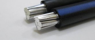
2.4. ALUMINUM STEEL WIRES
Steel-aluminum wires consist of a steel core of twisted aluminum wires. The core of steel-aluminum wires is twisted from galvanized steel wires in accordance with GOST 9850-72. On top of the steel core in steel-aluminum wires of the AS, ASK, ASKP and ASKS brands, strands of AT aluminum wire are applied in alternating directions, and in wires of the ApS, ApSK, ApSKP and ApSKS brands, strands of ATp wires are applied in accordance with GOST 6132-79. The outer heave has a right direction. The connection of solid core wire is not allowed. In wires with more than seven wires, connections are allowed in all layers. The splicing of wires is carried out at speed, the distance between the places of welding of different wires or the same wire is at least 15 m. The place of welding of wires is annealed at a distance of no more than 0.2 m in both directions. The appearance of the AC and ApS wires is shown in Fig. 2.2. In ApSKP, ApSKS, ASKP and ASKS wires, the gaps between the galvanized steel wires of the core are filled with a neutral lubricant of increased heat resistance, and in ApSK and ASK wires, the steel core is wrapped or covered longitudinally with one or two strips of PET (lavsan) film. Design data of wires ApS, ApSK, ApSKP, ApSKS, AS, ASK, ASKP and ASKS, weight, conversion factor of the mass of steel-aluminum wires to the mass of copper wires (used when planning non-insulated wires), tensile failure load, electrical resistance over a length of 1 km and The lengths of the supplied wires are given in table. 2.5. In the marking of the cross-section of steel-aluminum wires, the cross-section of aluminum wires is given in the numerator, and the cross-section of galvanized steel wires is given in the denominator.
The predominant area of application for APS and AS wires is in air types I and II, provided that the sulfur dioxide content in the atmosphere is no more than 150 mg/(m2*day) (1.5 mg/m3, on land in all macroclimatic regions according to GOST 15150-69 , except for vehicles and TV; wires ApSK, ASK, ApSKS and ASKS - on the coasts of seas, salt lakes, in industrial areas and areas of saline sand, as well as in adjacent areas with an air atmosphere of types II and III, provided that the atmosphere contains sulfur dioxide gas no more than 150 mg/ (m>2*day) (1.5 mg/m3 and chloride salts no more than 200 mg/ (m2*day) on land in all macroclimatic regions according to GOST 15150-69, except for TV; ApSKP wires and ASCP on the coasts of seas, salt lakes, in industrial areas and areas of saline sand, as well as in adjacent areas with an air atmosphere of types II and III on land and at sea in all macroclimatic regions according to GOST 15150-69.
The service life of AS and ApS wires is at least 45 years, ApSKP and ASKP wires are at least 25 years, and ApSK, ApSKS, ASK and ASKS wires are at least 10 years.
Figure 2.2. Bare AC Wire
Table 2.5. Design data of steel-aluminum wires of the brands ApS, ApSK, ApSKP, ApSKS, ApSKS, AS, ASK, ASKP, ASKS
| S*, mm2 | n*d, mm | D, mm | Coefficient of conversion of natural mass to copper mass | g, kg/km | Breaking tensile load, kN, not less | R, Ohm, no more | Wire length, m, not less | ||||||
| steel | aluminum | aluminum parts of all brands | AS, ApS | ASK, ApSK | ASKP, ApSKP | ASKS, ApSKS | AT | ATp | |||||
| 1*1,50 | 6*1,50 | 4,5 | 1,36 | 28,9 | 42,7 | 43,26 | 43,7 | 43,7 | — | 4,09 | 2,7663 | 3000 | |
| 1*1,85 | 6*1,85 | 5,6 | 1,36 | 44,0 | 64,9 | 65,46 | 65,9 | 65,9 | — | 6,22 | 1,800934 | 3000 | |
| 1*2,30 | 6*2,30 | 6,9 | 1,36 | 67,9 | 100,3 | 100,86 | 101,8 | 101,8 | — | 9,3 | 1,1759 | 3000 | |
| 1*2,80 | 6*2,80 | 8,4 | 1,36 | 100,0 | 148,0 | 148,84 | 150,5 | 150,5 | — | 13,5 | 0,7897 | 3000 | |
| 1*3,20 | 6*3,20 | 9,6 | 1,36 | 132,0 | 195,0 | 195,84 | 198 | 198 | 16,64 | 17,11 | 0,60298 | 3000 | |
| 1*3,80 | 6*3,80 | 11,4 | 1,36 | 188,0 | 276,0 | 278,12 | 300,5 | 300,5 | 23,47 | 24,13 | 0,42859 | 2000 | |
| 19*2,20 | 18*2,20 | 15,4 | 2,0 | 188,0 | 755,0 | 777,0 | 793 | 793 | — | 96,83 | 0,42760 | 2000 | |
| 1*4,50 | 6*4,50 | 13,5 | 1,36 | 261,0 | 385,0 | 386,4 | 391 | 391 | 32,43 | 33,37 | 0,30599 | 1500 | |
| 37*2,20 | 24*2,20 | 19,8 | 2,0 | 251,0 | 1357,0 | 1387 | 1420 | 1426 | — | 180,78 | 0,32108 | 1500 | |
| 7*1,85 | 26*2,40 | 15,2 | 1,38 | 324,0 | 471,0 | 482 | 506 | 482 | — | 41,52 | 0,24917 | 2000 | |
| 7*2,20 | 30*2,20 | 15,4 | 1,22 | 320,0 | 528, | 542 | 565 | 542 | — | 49,47 | 0,25293 | 2000 | |
| 7*1,85 | 24*2,80 | 16,8 | 1,48 | 407,0 | 554,0 | 565 | 596 | 566 | — | 46,31 | 0,19919 | 2000 | |
| 7*2,10 | 26*2,70 | 17,1 | 1,37 | 409,0 | 599,0 | 612 | 643 | 613 | — | 52,28 | 0,19798 | 2000 | |
| 7*2,50 | 30*2,50 | 17,5 | 1,21 | 406,0 | 675,0 | 692 | 723 | 693 | — | 62,64 | 0,20065 | 2000 | |
| 7*2,10 | 24*3,15 | 18,9 | 1,47 | 515,0 | 705 | 718 | 758 | 719 | 56,24 | 58,08 | 0,15701 | 2000 | |
| 7*2,30 | 26*2,98 | 18,8 | 1,38 | 500,0 | 728 | 743 | 780 | 744 | 59,63 | 62,06 | 0,16218 | 2000 | |
| 7*2,80 | 30*2,80 | 19,6 | 1,21 | 509,0 | 846 | 866 | 907 | 869 | — | 77,77 | 0,15762 | 2000 | |
| 37*2,10 | 54*2,10 | 23,1 | 2,0 | 517,0 | 1525 | 1552 | 1626 | 1588 | — | 183,82 | 0,15762 | 2000 | |
| 7*2,20 | 24*3,30 | 19,8 | 1,47 | 566,0 | 774 | 788 | 831 | 789 | 61,73 | 63,74 | 0,14294 | 2000 | |
| 7*2,40 | 24*3,60 | 21,6 | 1,47 | 673,0 | 921 | 937 | 987 | 938 | 72,66 | 75,05 | 0,12060 | 2000 | |
| 7*2,65 | 26*3,40 | 21,6 | 1,37 | 650,0 | 952 | 970 | 1023 | 974 | 78,58 | 80,90 | 0,12428 | 2000 | |
| 7*3,20 | 30*3,20 | 22,4 | 1,21 | 665,0 | 1106 | 1131 | 1184 | 1136 | 95,89 | 98,25 | 0,12182 | 2000 | |
| 7*2,65 | 24*4,00 | 24,0 | 1,47 | 830,0 | 1132 | 1150 | 1219 | 1154 | 89,16 | 90,57 | 0,09747 | 2000 | |
| 7*2,95 | 26*3,80 | 24,1 | 1,37 | 812,0 | 1186 | 1208 | 1273 | 1213 | 97,76 | 100,62 | 0,09983 | 2000 | |
| 19*2,10 | 30*3,50 | 24,5 | 1,22 | 796,0 | 1313 | 1333 | 1408 | 1350 | 123,44 | 126,3 | 0,10266 | 2000 | |
| 7*3,50 | 30*3,50 | 24,5 | 1,21 | 796,0 | 1323 | 1343 | 1418 | 1360 | 114,70 | 117,52 | 0,10266 | 2000 | |
| 37*2,65 | 54*2,65 | 29,2 | 2,0 | 823,0 | 2428 | 2467 | 2578 | 2530 | — | 284,58 | 0,09934 | 2000 | |
| 7*2,30 | 48*2,98 | 24,8 | 1,6 | 924,0 | 1152 | 1166 | 1264 | 1168 | 84,56 | 88,85 | 0,08799 | 2000 | |
| 7*2,80 | 54*2,80 | 25,2 | 1,47 | 918,0 | 1255 | 1276 | 1368 | 1278 | — | 103,80 | 0,08888 | 2000 | |
| 7*1,85 | 42*3,40 | 26,0 | 1,73 | 1052,0 | 1199 | 1211 | 1330 | 1211 | 81,86 | 85,6 | 0,07752 | 1500 | |
| 7*2,00 | 76*2,57 | 26,6 | 1,73 | 1089,0 | 1261 | 1273 | 1396 | 1273 | — | 95,12 | 0,07501 | 1500 | |
| 7*3,05 | 54*3,05 | 27,5 | 1,47 | 1090,0 | 1490 | 1514 | 1624 | 1518 | 115,40 | 120,48 | 0,07477 | 1500 | |
| 7*3,40 | 26*4,37 | 27,7 | 1,37 | 1074,0 | 1572 | 1600 | 1707 | 1607 | 125,37 | 129,18 | 0,07528 | 1500 | |
| 19*2,50 | 30*4,15 | 29,1 | 1,21 | 1119,0 | 1851 | 1878 | 2000 | 1904 | 169,74 | 173,72 | 0,07247 | 1500 | |
| 7*3,20 | 54*3,20 | 28,8 | 1,47 | 1199,0 | 1640 | 1665 | 1785 | 1670 | 127,11 | 131,37 | 0,06786 | 1500 | |
| 7*2,20 | 42*3,90 | 30,0 | 1,73 | 1384,0 | 1592 | 1606 | 1750 | 1607 | 107,28 | 112,19 | 0,05877 | 1500 | |
| 7*2,20 | 76*2,84 | 29,4 | 1,74 | 1329,0 | 1537 | 1551 | 1689 | 1552 | 106,40 | 112,55 | 0,06129 | 1500 | |
| 7*3,40 | 54*3,40 | 30,6 | 1,47 | 1354,0 | 1852 | 1880 | 2015 | 1885 | 143,45 | 148,26 | 0,06040 | 1500 | |
| 37*2,65 | 90*2,65 | 34,5 | 2,0 | 1374,0 | 2979 | 3002 | 3209 | 3084 | 312,31 | 319,61 | 0,06025 | 1500 | |
| 61*2,65 | 54*3,40 | 37,5 | 2,0 | 1355,0 | 4005 | 4054 | 4275 | 4173 | 461,83 | 466,65 | 0,06040 | 1500 | |
| 7*3,60 | 54*3,60 | 32,4 | 1,47 | 1518,0 | 2076 | 2106 | 2260 | 2114 | 160,78 | 166,16 | 0,05381 | 1200 | |
| 19*2,20 | 54*3,70 | 33,2 | 1,48 | 1603,0 | 2170 | 2192 | 2364 | 2209 | 178,15 | 183,84 | 0,05091 | 1200 | |
| 19*2,30 | 96*2,90 | 34,7 | 1,48 | 1752,0 | 2372 | 2395 | 2602 | 2414 | 192,37 | 200,45 | 0,04655 | 1000 | |
| 19*2,40 | 96*3,02 | 36,2 | 1,48 | 1900,0 | 2575 | 2599 | 2828 | 2621 | 209,01 | 217,78 | 0,04289 | 1000 | |
| 19*2,50 | 96*3,15 | 37,7 | 1,48 | 2068,0 | 2800 | 2827 | 3072 | 2849 | 227,11 | 234,45 | 0,03939 | 1000 | |
| 19*2,65 | 96*3,30 | 39,7 | 1,48 | 2269,0 | 3092 | 3121 | 3402 | 3149 | 252,02 | 260,07 | 0,03586 | 1000 | |
| 7*3,20 | 76*4,10 | 42,4 | 1,48 | 2769,0 | 3210 | 3235 | 3565 | 3240 | 214,21 | 224,05 | 0,02936 | 1000 | |
2.5. COPPER WIRES
Copper wires grade M are twisted from copper wires grade MT according to GOST 2112-79. The structural dimensions of the copper wire, mass, tensile failure load, electrical resistance over a length of 1 km and the length of the supplied wires are given in table.
2.6. The connection of individual wires when twisting the wire is done by welding. The distance between the points of connection of different or the same wire is at least 15 m. The place where the wires are welded is annealed on each side of the connection for a distance of no more than 0.2 m in both directions. Solid copper wire connection is not allowed.
The primary area is the use of copper wires in the air atmosphere of types II and III on land and sea in all macroclimatic regions according to GOST 15150-69. The service life of grade M copper wires is at least 45 years.
Table 2.6. Design data and parameters of copper wire grade M
| S, mm2 | n*d, mm | D, mm | g, kg/km | Breaking tensile load, kN, no more | R, Ohm, no more | Wire length, m, not less |
| 4,0 | 1*2,24 | 2,24 | 35 | 1,55 | 4,60092 | 2200 |
| 6,0 | 1*2,76 | 2,8 | 52 | 2,30 | 3,09019 | 1500 |
| 10,0 | 1*3,57 | 3,6 | 88 | 3,67 | 1,81978 | 900 |
| 16,0 | 7*1,70 | 5,1 | 142 | 5,91* | 1,15730 | 4000 |
| 25,0 | 7*2,13 | 6,4 | 224 | 9,29* | 0,73367 | 3000 |
| 35,0 | 7*2,51 | 7,5 | 311 | 12,90* | 0,52386 | 2500 |
| 50,0 | 7*3,00 | 9,00 | 444 | 17,50* | 0,36882 | 2000 |
| 70,0 | 19*2,13 | 10,7 | 612 | 25,22 | 0,27238 | 1500 |
| 95,0 | 19*2,51 | 12,6 | 850 | 35,02 | 0,19449 | 1200 |
| 120,0 | 19*2,80 | 14,0 | 1058 | 43,60 | 0,15603 | 1000 |
| 150,0 | 19*3,15 | 15,8 | 1338 | 52,39 | 0,12338 | 800 |
| 185,0 | 37*2,51 | 17,6 | 1659 | 68,20 | 0,10015 | 800 |
| 240,0 | 37*2,80 | 19,9 | 2124 | 87,30 | 0,07890 | 800 |
| 300,0 | 37*3,15 | 22,1 | 2614 | 101,96 | 0,06379 | 600 |
| 350,0 | 37*3,45 | 24,2 | 3135 | 122,67 | 0,05309 | 600 |
| 400,0 | 37*3,66 | 25,2 | 3528 | 137,68 | 0,04713 | 600 |
| * In the absence of welding of individual wires. | ||||||
2.6. BRONZE, STEEL BRONZE AND STEEL WIRES
Bronze and steel-bronze wires of grades B and BS are made from BrMg 0.5 alloy according to TU 48.21.118-72. The design of wire B, electrical resistance to direct current over a length of 1 km, tensile failure load, mass and length are given in Table. 2.7, and the BS wires are in table. 2.8. Length of wires (1800±180) m. The core of steel-bronze wires is twisted from galvanized steel wire in accordance with GOST 9850-72.
PS grade steel stranded wires are made from galvanized steel wires in accordance with GOST 3282-74 group I with 1st class zinc coating. Breaking load when stretching the wire is 0.065 kN, relative elongation is not less than 6%, the number of bends is 6, the electrical resistivity at 20ºC is not more than 1.38 * 10-7 Ohm * m. The wire design is given in table. 2.9. The twist pitch of wires from 5 and 7 wires is no more than 22 >D wires, and from 12 and 19 wires - no more than 20 D. In a wire, individual wires can be spliced by welding, the distance between welding points is at least 5 m. Welding points must be protected from corrosion and annealed. Wires are supplied in lengths of at least 1500 m.
Table 2.7. Design data and parameters of bronze wire grade B
| S, mm2 | n*d, mm | D, mm | g, kg/km | R, Ohm, no more | Breaking tensile load, kN, not less |
| 50,0 | 19*1,83 | 9,2 | 452 | 0,624 | 23,80 |
| 70,0 | 19*2,17 | 10,9 | 642 | 0,447 | 33,48 |
| 95,0 | 19*2,53 | 12,7 | 872 | 0,326 | 45,51 |
| 120,0 | 19*2,80 | 14,0 | 1069 | 0,266 | 55,72 |
| 150,0 | 37*2,27 | 15,9 | 1374 | 0,2089 | 68,20 |
| 185,0 | 37*2,53 | 17,7 | 1706 | 0,1676 | 84,70 |
| 240,0 | 37*2,86 | 20,0 | 2181 | 0,1312 | 108,10 |
| 300,0 | 61*2,53 | 22,8 | 2801 | 0,1026 | 139,62 |
Table 2.8. Design data and parameters of steel-bronze wire grade BS
| S, mm2 | n*d, mm | D, mm | g, kg/km | R, Ohm, no more | Breaking tensile load, kN, not less | |
| steel | bronze | |||||
| 185 | 7*2,0 | 30*2,8 | 19,6 | 2088 | 0,1688 | 134,00 |
| 240 | 19*2,8 | 46*2,55 | 24,2 | 3122 | 0,1333 | 232,63 |
| 300 | 37*2,4 | 48*2,8 | 28,0 | 4102 | 0,1058 | 312,63 |
| 400 | 37*2,8 | 48*3,2 | 32,4 | 5347 | 0,0825 | 421,69 |
Table 2.9. Design data and parameters of wire made of PS grade galvanized steel wire
| S, mm2 | n*d, mm | D, mm | g, kg/km |
| 25 | 5*2,5 | 6,8 | 194,3 |
| 35 | 7*2,5 | 7,5 | 272,0 |
| 50 | 9*2,3 + 3*2,2 | 9,2 | 389,4 |
| 70 | 12*2,3 + 7*2,2 | 11,5 | 616,6 |
2.7. ALUMINUM AND COPPER HOLLOW WIRES
Aluminum and copper hollow wires without a supporting support are intended for overhead power lines, for open substations and switching points. Hollow wires consist of shaped aluminum or copper wires, forming one layer and connected to each other in a lock (without a supporting frame). The appearance of the PA and PM wires is shown in Fig. 2.3. The design of hollow wires PA and PM, the weight and length of the supplied wire are given in table. 2.10. The breaking load when stretching aluminum wire before twisting into a wire is no less than 0.145 kN and copper wire is no less than 0.38 kN with a relative elongation at break of no less than 1%. The electrical resistance of an aluminum wire to direct current, recalculated per 1 mm2 of nominal cross-section, 1 m of length and 20ºC is no more than 0.0283 Ohm, and that of a copper wire is no more than 0.0179 Ohm.
Figure 2.3. Hollow wires PA and PM
Table 2.10. Design data and parameters of hollow wires of PA and PM brands
| Brand | S, mm2 | Number of wires | D, mm | g, kg/km | Wire length, m | |
| outer | interior | |||||
| PA | 500 | 12 | 45,0 | 37,0 | 1330 | 600 |
| 640 | 16 | 59,0 | 51,5 | 1620 | 600 | |
| PM | 240 | 9 | 30,0 | 23,4 | 2110 | 600 |
| 300 | 11 | 35,0 | 28,0 | 2630 | 600 | |
2.8. BRONZE, COPPER AND ALUMINUM STEEL CONTACT WIRE
Bronze, copper and steel-aluminum contact wires are designed to power electrified transport. The appearance of the contact wires BrF and MF is shown in Fig. 2.4, cross-section of contact wires BrF and MF - in Fig. 2.5, cross-section of contact wires BrFO and MFO in Fig. 2.6. The design dimensions, weight and length of the supplied wires are given in table. 2.11. The contact surface of the wires is smooth, even, without cracks, sunsets or delaminations. Wires of all types, with the exception of wires made of cadmium bronze, are supplied seamless (without soldering or welding) along the entire construction length. For wires made of cadmium bronze, the number of joints (soldering and welding} is no more than four per 1 ton.
Copper contact wire is made from wire rod of the MKLPS brand in accordance with GOST 13842-80, low-alloy and bronze wires are made from wire rod containing alloying additives and impurities (Table 2.12). The mechanical properties of the wires are given in table. 2.13. The wires are maintained until they fail in the plane of symmetry at least three kinks. The number of twists around its axis until destruction of wires of the MK, MF, MFO, NLF, NLFO brands with a cross-section of over 50 mm2 is at least four, and for BrF and BrFO wires - at least five. The electrical resistance of a copper wire to direct current, recalculated per 1 mm2 of nominal cross-section, 1 m of length and 20ºC, is no more than 0.0176 Ohm, low-alloy wire - 0.0185 Ohm, cadmium bronze wire - no more than 0.0205 Ohm, magnesium bronze - no more than 0.0220 Ohm, zirconium bronze - no more than 0.0200 Ohm, magnesium-zirconium bronze - no more than 0.0215 Ohm.
Steel-aluminum contact wires are made by joining steel and aluminum blanks using the cold rolling method. They are designed for tram and trolleybus traction. The appearance of the contact wire PKSA is shown in Fig. 2.7. Wire cross-section 180 mm2 (aluminum cross-section 125 mm2), profile height 17 mm, heads 3.7 mm, base width 14 mm, necks 5.7 mm, heads 3.2 mm. Wire weight 760 kg/km, length no less than 2300 m. The contact surface of the wire is smooth, even, without cracks, sunsets or delaminations. The wire is made of low-carbon steel in accordance with GOST 1050-74 and an extruded profile made of aluminum grades A5, AE in accordance with GOST 11069-74. The workpieces are connected by electric butt welding, the distance between the welds of aluminum and steel in the finished wire is at least 5 m, the tensile breaking load is at least 35.0 kN, and at the welding points is at least 29.75 kN. The adhesion force of steel and aluminum parts is at least 5 kN per 100 mm of length. Electrical resistance over a length of 1 km at a temperature of 20±5 is not less than 0.19 Ohm. Delamination of a wire (steel part from aluminum) at the place of greatest deformation after a single twist of 180º, followed by return to its original position on a sample 250 mm long and at the place of greatest deformation after one bend of 50º in a plane perpendicular to the plane of symmetry, and two bends of 45º in the plane of symmetry should not exceed 1.2 mm.
Figure 2.4. Contact wires BF and MF
Figure 2.5. Section of contact wires BF and MF
Figure 2.6. Cross-section of contact wires BFO and MFO
MFO, NLF and NLFO (Fig. 2.5, 2.6)
| S, mm2 | Dimensions, mm | g, kg/km | Wire length, m, not less | |||||||||
| BrF, MF, NLF | BrFO, MFO, NLFO | MK | ||||||||||
| A | N | WITH | R | A | N | WITH | R | R1 | ||||
| 30 | — | — | — | — | — | — | — | — | — | 6,2 | 267 | 1800-5500 |
| 40 | — | — | — | — | — | — | — | — | — | 7,1 | 356 | 1400-4200 |
| 50 | — | — | — | — | — | — | — | — | — | 8,0 | 445 | 1100-3300 |
| 65 | 10,19 | 9,3 | 0,5 | 5,3 | — | — | — | — | — | 9,1 | 578 | 850-2500 |
| 85 | 11,76 | 10,8 | 1,3 | 6,0 | — | — | — | — | — | 10,4 | 755 | 1400-2000 |
| 100 | 12,81 | 11,8 | 1,8 | 6,5 | 14,92 | 10,5 | 13,0 | 20,0 | 1,8 | 11,3 | 890 | 1400-1800 |
| 120 | 13,90 | 12,9 | 2,4 | 7,0 | 16,10 | 11,5 | 17,0 | 25,0 | 2,3 | — | 1068 | 1400-1800 |
| 150 | 15,50 | 14,5 | 3,2 | 7,8 | 18,86 | 12,5 | 27,0 | 36,0 | 2,3 | — | 1335 | 1400-1600 |
Figure 2.7. PKSA contact wire cross-section
Table 2.12. Content of alloying additives in wire rod for bronze and low-alloy wires
| Brand | Alloying component | Content, % |
| Low alloy | ||
| NLMG 0.05 | Magnesium | 0,04-0,06 |
| NLCr 0.05F | Zirconium | 0,04-0,06 |
| MLOL 0.04F | Tin | 0,03-0,06 |
| NKLr 0.04F | Silicon | 0,03-0,06 |
| NLTi 0.03F | Titanium | 0,01-0,04 |
| Bronze* | ||
| BrMG 0.25F | Magnesium | 0,15-0,30 |
| BrKd 1.0F | Cadmium | 0,8-1,1 |
| BrMGTsr 0.15-0.15F | Magnesium | 0,1-0,2 |
| Zirconium | 0,1-0,2 | |
| BrTsr 0.5F | ” | 0,4-0,6 |
| * Alloying component in copper. | ||
| Note. Impurities in the alloy are no more than in copper grade M1 | ||
Table 2.13. Mechanical properties of contact wires MK, MF, MFO, NLF, NLFO, BrF and BrFO
| S, mm2 | Breaking tensile load, kN, not less | Relative elongation, %, not less | Flexible radius, mm | |||||||
| MK, MF, MFO | NLF, NLFO | BrF and BrFO, alloyed | MK, MF, MFO | NLF, NLFO | BrF, BrFO | |||||
| magnesium | zirconium | magnesium and zirconium | cadmium | |||||||
| 30 | 3,97 | 4,02 | — | — | — | — | 1,5 | 1,5 | — | 10 |
| 40 | 3,87 | 3,92 | — | — | — | — | 2,0 | 2,0 | — | 10 |
| 50 | 3,87 | 3,92 | — | — | — | — | 2,5 | 2,5 | — | 10 |
| 65 | 3,72 | 3,82 | 4,21 | 4,41 | 4,31 | 4,31 | 3,0 | 3,0 | 3,0 | 13 |
| 85 | 3,63 | 3,82 | 4,21 | 4,41 | 4,31 | 4,31 | 3,5 | 3,0 | 3,0 | 16 |
| 100 | 3,63 | 3,77 | 4,12 | 4,31 | 4,21 | 4,21 | 4,0 | 3,5 | 3,5 | 16 |
| 120 | 3,58 | 3,67 | 4,02 | 4,21 | 4,12 | 4,22 | 4,0 | 3,5 | 4,0 | 18 |
| 150 | 3,58 | 3,62 | 3,92 | 4,12 | 4,02 | 4,02 | 4,0 | 3,5 | 4,0 | 20 |
What is a cord?
Cord is a wire consisting of two or more insulated flexible conductors with a cross-section of up to 1.5 mm, covered with a non-metallic sheath or other protective coverings. The cord is used to connect electrical household appliances (table lamps, vacuum cleaners, washing machines) to the network. The core of the cord must be multi-wire; in addition, the cores are connected to each other by twisting or a common braid.
Two-core cords are used if the device body does not require protective grounding; if grounding is required, then three-core cords are used.
Parameter overview
Wire flexibility class
The main part of the cable structure is a metal core through which electric current flows. The main parameters are DC resistance, throughput and cross-section. All cores are produced in accordance with regulatory documents that define the standard for direct current resistance of 1 km of core at 20°C (GOST 22483-77).
The permissible current for copper wires depends on the total power of consumers and the voltage of the electrical circuit. It is calculated by the formula: I= P/V and is 10A per 1 mm2.
The wire class ranges from 1 to 6, the higher the number, the greater the flexibility. For stationary fixed wiring, class 1–2 products are used. For mobile mechanisms, flexible wire with a class of 3 to 6 is suitable.
According to the PUE, the most rational cross-section of copper wire in networks with household appliances is 1.5–2.5 mm2 for sockets; 0.75–1.5 mm2 is sufficient for lighting.
Electrical wires for indoor installation
Electrical wires for internal wiring are somewhat different from power cables - first of all, these differences relate to their technical characteristics and the cross-section of the wire itself. There are quite a lot of varieties of such electrical wires, as well as cable products, and therefore the question of their choice is quite acute.
PBPP (PUNP) - installation wire with flat single cores placed in PVC insulation and the same outer sheath. It can have from one to three cores with a maximum cross-section of 6 squares. In most cases, it is used for lighting electrical wiring - it is not excluded that it can be used to connect sockets, but on the condition that they will include low-power consumers. They can have both copper and aluminum conductors - in the latter case they are marked as APBPP.
PBPPg (PUGNP). Their main difference from PBPP lies in the cores themselves - they are twisted and consist of thin wires. The letter “g” at the end of the marking indicates that this wire is flexible.
PPV. Single-core copper wire - recommended for hidden electrical wiring or for installation in a corrugated or cable duct. Has single insulation.
APPV is the same as PPV, only with an aluminum conductor.
APV is one of the types of PPV. It differs from it in an aluminum twisted conductor, consisting of wires tightly wound together. Produced in sections up to 16 squares.
PVS . This is one of the most common brands of electrical wires and cables - the sheath and its insulation are made of PVC. Its distinctive feature is its round cross-section and twisted conductors. The cross-section of such electrical wires can vary from 0.75 to 16 squares. As a rule, it is used to connect household electricity consumers - wiring is not installed with this wire.
SHVVP is a copper or copper-tinned flat electrical wire intended for household needs. Just like PVA, it is used to connect household consumers. This is a twisted electrical wire, the cores of which consist of thin wires - it can have a cross-section from 0.5 to 16 squares.
Below are tables for selecting a specific brand of wire or cable depending on the conditions of use.
Characteristics of copper wires and cables
The design of the cable depends on the conditions in which it is used. But regardless of the variety, there are 4 main elements: conductive cores, insulation, sheath, and outer protective cover.
What insulating layer
The role of insulation is to prevent human contact with the circuit through which the current flows. It also protects against short circuits between adjacent phases.
The insulating layer comes in several types, and serious requirements are placed on the material: it must withstand a specific voltage, temperature changes, UV radiation, and have the necessary mechanical properties. The following have proven themselves in practice:
- PVC. An affordable wear-resistant material with good chemical resistance. The disadvantage of plastic is that when heated strongly, it begins to release harmful substances;
- rubber. The advantage of the rubber insulating layer is that it is flexible and can withstand negative temperatures;
- polyethylene. It has high dielectric properties, but is inferior in flexibility to PVC and rubber;
- carbolite Plastic and heat-resistant option.
Important! Each core is insulated to prevent electrical breakdown.
You may be interested in this Color coding of wires
There is also belt insulation, the main one, which is applied on top of all the cores.
Previously, wires were insulated with specially impregnated paper. Now, when it comes to power cables, polymer and rubber insulation are used.
Impregnation for paper wire is usually synthetic insulating resins or viscous compositions of rosin and oil, to which other components are added. Such products have limitations in terms of use, which relate to areas with differences in height (when the resin heats up, it begins to flow down). If vertical sections are laid, impregnation of high viscosity is allowed.
Note! Vulcanized rubber insulation is suitable for networks with alternating current up to 1 kW and direct current up to 10 kW. The rubber is applied as a continuous layer, but there are also options in the form of tapes.
As for polymer insulation, its material is polyvinyl chloride (PVC) or cross-linked polyethylene (XPE). To increase the fire safety of the wire, a special coating is applied to it. Polyethylene allows the production of light and flexible cables. This material retains its properties when exposed to ultraviolet radiation, low and high temperatures (it can be heated up to 90 ° C).
The quality of insulation depends on the operating conditions
What section
To determine the cross-section of the wire, you need to cut it crosswise and pay attention to the cut. The area will be the value of the section. The larger it is, the greater the current the wire can transmit. For products with a single wire this value is up to 16 mm², multi-core - 120-800 mm².
Before designing any electrical network, it is necessary to select a cable with suitable parameters, and the main one is the cross-section. The performance of a reliable network will depend on it. If the parameter is calculated incorrectly, there is a high probability that the network will simply be overloaded, which can lead to serious consequences.
Important! If a cable is used to its limits, it will overheat significantly and eventually fail.
To correctly calculate the cross-section, you need to know the following parameters: network voltage, current, consumer power. The key value is the maximum permissible current load. Section selection algorithm:
- The total load power is determined.
- The current strength is calculated.
- The section is selected (based on the table).
For example, the task is selecting a cable for a household network. First of all, determine the total power of all connected electrical appliances. This is easy to do - just calculate the entire load. Each device has its own power value, which is indicated in the technical data sheet. The formula for calculating current strength for single-phase networks looks like this: I = P / 220 (P is the total power, measured in kW, 220 is voltage).
You may be interested in this Features of the installation wire
For three-phase networks, a different formula is used: I = P / √3×380. Based on the obtained figure, it is enough to select the cross-section value from the table presented.
Section table
WIRE GRADES
| Brand | Core cross-section, mm | Number of cores | Characteristic | Application |
| Automatic reclosing | 2,5-120 | 1 | Wire with aluminum core, polyvinyl chloride insulation | For installation of power and lighting networks in pipes and channels |
| APPV | 2,5-6 | 2; 3 | Wire with aluminum conductors, polyvinyl chloride insulation, flat, with dividing base | For installation of power and lighting networks on walls, partitions, hidden wiring, in pipes, channels |
| APR | 2,5-120 | 1 | Wire with aluminum core, rubber insulation, braided with cotton yarn. impregnated with anti-rotten composition | For installation in pipes |
| APPR | 2,5-6 | 2; 3 | Wire with aluminum conductors, rubber insulation | For laying on wooden structures of residential and industrial buildings |
| APRN | 2,5-120 | 1 | Wire with aluminum core, rubber insulation, in a non-flammable sheath | For laying in dry and damp rooms, in channels, outdoors. |
| PV-1 | 0,5-95 | 1 | Wire with copper core, polyvinyl chloride insulation | For installation of power and lighting networks in pipes and channels |
| PV-2 | 2,5-95 | 1 | Wire with copper core, polyvinyl chloride insulation, flexible | For installation of power and lighting networks in pipes and channels |
| PPV | 0,75-4 | 2; 3 | Wire with copper cores, polyvinyl chloride insulation, flat, with a separating base | For installation of power and lighting networks on walls, partitions, hidden wiring, in pipes, channels |
| ETC | 0,75-120 | 1 | Wire with copper core, rubber insulation, braided with cotton yarn, impregnated with anti-rotten composition | For installation in pipes |
| PVS | 0,5-2,5 | 2; 3 | The wire is flexible, with twisted with copper conductors, polyvinyl chloride insulation, polyvinyl chloride shell | For connecting household electrical appliances - washing machines, vacuum cleaners, extension cords |
| PRS | 0,5-4 | 2; 3 | Flexible wire, with twisted copper cores, rubber insulation, rubber sheath | For connecting household electrical appliances - washing machines, vacuum cleaners, extension cords |
| PUNP (PBPP) | 1,5-4 | 2; 3 | Wire with copper core, polyvinyl chloride insulation, polyvinyl chloride sheath | For laying in lighting networks, installation and connection of low current household appliances appointments |
| MGS | 0,05-0,12 | 1 | Installation wire, flexible with copper core, with silk insulation | For stationary and mobile installation of intra-unit and inter-unit connections in electronic and electrical devices |
| MGSHV | 0,12-1,5 | 1 | Installation wire, flexible, with copper core, with combined silk and polyvinyl chloride isolation | For stationary and mobile installation of intra-unit and inter-unit connections in electronic and electrical devices |
| TRP (noodles) | 0,4-0,5 | 2 | Wire with copper core, polyethylene insulation, with dividing base | For open and hidden wiring of telephone network |
Advantages and disadvantages of copper wires and cables
Copper cables are in great demand for a reason; they have significant advantages when compared with their aluminum counterpart:
- less resistance. This makes it possible to reduce the cross-sectional diameter and reduce heating losses. They can also withstand higher voltages;
- resistant to corrosion processes. 30-35 years - this is how long networks last on average before they have to be replaced;
- high plasticity. Soft copper cables are easier to install;
- don't burn. Even if one wire ignites, the fire will not spread to the others;
- Some cables are equipped with stranded cores. They are used to connect mobile consumers, for example, household electrical appliances.
Copper wire coil
There are also disadvantages:
- price (copper conductors are approximately 2 times more expensive than aluminum conductors);
- considerable weight (if the line is installed by air, it requires strong structures, and in large quantities).
For your information! Even oxidized copper retains its properties.
Plasticity is one of the key advantages
CABLE BRANDS
| Brand | Core cross-section, mm | Number of cores | Characteristic | Application |
| AVVG | 2,5-50 | 1; 2; 3; 4 | Power cable, with aluminum cores, polyvinyl chloride insulation, in a polyvinyl chloride sheath | For installation outdoors , along routes protected from direct sunlight |
| AVRG | 4-300 2,5-300 | 1; 2; 3; 4 | Power cable, with aluminum cores, rubber insulation, in a polyvinyl chloride sheath | For laying in the air at absence of mechanical influences, in dry or damp rooms, tunnels, canals, special cable overpasses and bridges |
| ANRG | 4-300 2,5-300 | 1; 2; 3; 4 | Power cable, with aluminum conductors, rubber insulation, in rubber oil-resistant and non-flammable shell | For laying in the air at absence of mechanical influences, in dry or damp rooms, tunnels, canals, special cable overpasses and bridges |
| VVG | 1,5-50 2,5-50 | 1; 2; 3; 4 | Power cable, with copper cores, polyvinyl chloride insulation, in a polyvinyl chloride sheath | For installation outdoors , along routes protected from direct sunlight |
| VRG | 1-240 | 1; 2; 3; 4 | Power cable, with copper cores, rubber insulation, in a polyvinyl chloride sheath | For laying in the air at absence of mechanical influences, in dry or damp rooms, tunnels, canals, special cable overpasses and bridges |
| NWG | 1-240 | 1; 2; 3; 4 | Power cable, with copper conductors, rubber insulation, in rubber oil-resistant and non-flammable shell | For laying in the air at absence of mechanical influences, in dry or damp rooms, tunnels, canals, special cable overpasses and bridges |
| NYM | 1,5-32 | 2; 3; 4; 5 | Power cable, with one or stranded copper core, polyvinyl chloride insulation, in flame retardant polyvinyl chloride shell. It has additional rubber layer-filling. | For installation of electrical wiring - in dry and wet conditions indoors, outdoors, out of direct exposure sunlight, in pipes, channels, on special cable racks, for connecting industrial installations, connecting household appliances in stationary installations |
Product varieties
Armored copper cable
The range of modern cable industry includes wires, cables with metal conductors, cords, tapes and other products. The main types of electrical wiring are network, through which information is transmitted, and power, for transmitting current. Depending on the purpose, there are the following types of wire products:
- actually, wires;
- power cables;
- products for telephone lines;
- computer;
- special purpose wires.
To systematize them there is a certain marking. Products are supplied in the form of pieces of various lengths, which are wound on a reel or rolled into a coil.
How to determine the cross-section of a stranded wire
Dependence of the cross-section of the conductor on the current strength.
The safety and reliability of electrical wiring in the house depends on the correct choice of wire. Overloads lead to overheating of the conductors, the insulation melts, which leads to a short circuit and fire.
The cross section is determined depending on the number of devices that will consume electricity. Therefore, it is necessary to calculate their total power used in the apartment. The result obtained is multiplied by 0.75. There are tables showing the relationship between cross section and current and power. The cross-section of a round cable can be determined by the formula:
S = π x r2, where π – 3.14; r2 – radius squared. The radius of the conductors is measured using a caliper; the thinnest ones are measured with a micrometer.
If there are several wires in the core, their total cross-section is calculated. It must correspond to the calculated one; some change upward from the standard is allowed. The indicator cannot be underestimated, since equipment may be added or replaced during operation. Therefore, when calculating, you need to use a coefficient of 1.5.