The main elements of overhead lines are wires, insulators, linear fittings, supports and foundations. On overhead lines of three-phase alternating current, at least three wires are suspended, constituting one circuit; on direct current overhead lines - at least two wires.
Based on the number of circuits, overhead lines are divided into single, double and multi-circuit. The number of circuits is determined by the power supply circuit and the need for its redundancy. If the power supply scheme requires two circuits, then these circuits can be suspended on two separate single-circuit overhead lines with single-circuit supports or on one double-circuit overhead line with double-circuit supports. The distance / between adjacent supports is called the span, and the distance between anchor-type supports is called the anchor section.
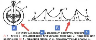
Wires suspended on insulators (A - the length of the garland) to the supports (Fig. 5.1, a) sag along the catenary line. The distance from the suspension point to the lowest point of the wire is called the sag /. It determines the size of the wire approaching the ground A, which for populated areas is equal to: to the surface of the earth up to 35 and PO kV - 7 m; 220 kV - 8 m; to buildings or structures up to 35 kV - 3 m; 110 kV - 4 m; 220 kV - 5 m. Span length / is determined by economic conditions. The span length up to 1 kV is usually 30...75 m; PO kV - 150...200 m; 220 kV - up to 400 m.
What is a power line?
High-voltage power lines are usually installed along large highways or in uninhabited areas. This approach increases safety and simplifies the design and maintenance of power lines.
AC voltage is transmitted along power lines; it provides a greater transmission distance compared to direct current. The value is selected based on the range, for example, 35-150 kV systems are installed between cities and large enterprises, and up to 20 kV inside populated areas. Trunk power lines operate at a voltage of about 220-500 kV. They are designed to connect city power systems to a station that generates electricity.
A number of specific terms are used among specialists:
- The route is the axis of the power transmission line laying along the surface of the earth.
- A picket is a section of a route with the same characteristics (the beginning of a power line is called zero, and their installation is called a picket).
- Span – the distance between the centers of nearby supports.
- The sag is the delta between the lowest point of the cable sag and the horizontal line between the supports.
The term "wire gauge" is also used. It means the distance between a slack cable and the top of the structures located underneath it. The listed concepts relate mainly to the design of overhead power lines. It is at this stage that the safety measures for the equipment itself, the people who will be involved in its maintenance, and those passing by are calculated.
Table 1. Typical dimensions of power lines
| Rated voltage, kV | Distance between phases, m | Span length, m | Support height, m |
| 0,5 | 40-50 | 8-9 | |
| 6-10 | 1 | 50-80 | 10 |
| 35 | 3 | 150-200 | 12 |
| 110 | 4-5 | 170-250 | 13-14 |
| 150 | 5,5 | 200-280 | 15-16 |
| 220 | 7 | 250-350 | 25-30 |
| 330 | 9 | 300-400 | 25-30 |
| 500 | 10-12 | 350-450 | 25-30 |
| 750 | 14-16 | 450-750 | 30-41 |
| 1150 | 12-19 | — | 33-54 |
Wire grades 110 kW.
The following brands of wires with a voltage of 110 kW are offered:
- A – uninsulated wire made of aluminum wire, concentrated twisting is used in manufacturing;
- AC - wire with aluminum conductor and steel core;
- Automatic transmission - a wire with an aluminum core, the space between the wires is filled with a heat-resistant lubricant;
- ASK - a wire with a conductive conductor made of aluminum, a steel core filled with heat-resistant lubricant;
- ASKS - a cable with an aluminum conductor and a steel core, while the outer surface of the core and the inter-wire space are filled with a heat-resistant lubricant;
- ASKP - a cable with an aluminum conductor, a steel core, the space between the wires (excluding the outer surface) is filled with heat-resistant lubricant;
- AT1/s – wire with a core of round wire made of AT3 alloy with a steel core;
- AT3/C – cable with a core made of wires made of aluminum-based alloy AT3 and a galvanized steel core;
- ACu is a wire with an aluminum core and a reinforced steel core; modification AC2u offers its strengthened version;
- AC2 is a wire made of an aluminum core and cores made of steel wire of group 2, a strengthened modification is supplied with the AC2u marking.
Wires for 110 kW power lines are designed to transport energy over long distances; they are characterized by their low specific gravity. All presented products are designed for operation for more than 45 years.
Wire grades 110 kW for power lines.
| AC500/336 | ASKP400/64 | AT1P/S150/24 |
| AC500/34.6 | ASKP400/93 | AT1P/S150/34 |
| AC500/64.8 | ASKP450/31.1 | AT1P/S185/24 |
| AC550/71 | ASKP450/56 | AT1P/S185/29 |
| AC560/38.7 | ASKP450/58.3 | AT1P/S185/43 |
| AC560/70.9 | ASKP50/8 | AT1P/S240/32 |
| AC600/72 | ASKP50/8.0 | AT1P/S240/39 |
| AC63/10.5 | ASKP500/204 | AT1P/S300/39 |
| AC630/43.6 | ASKP500/26 | AT1P/S300/67 |
| AC630/79.8 | ASKP500/27 | AT1P/S400/51 |
| AC650/79 | ASKP500/336 | AT1P/S500/64 |
| AC70/72.0 | ASKP500/34.6 | AT3/S120/19 |
| AC700/86 | ASKP500/64 | AT3/S150/24 |
| AC710/49.1 | ASKP500/64.8 | AT3/S150/34 |
| AC710/89.9 | ASKP550/71 | AT3/S185/24 |
| AC800/101.3 | ASKP560/38.7 | AT3/S185/43 |
| AS95/141 | ASKP560/70.9 | AT3/S240/32 |
| AC2240/32 | ASKP600/72 | AT3/S240/39 |
| AC2300/66 | ASKP63/10.5 | AT3/S300/39 |
| AS2u1000/56 | ASKP630/43.6 | AT3/S300/67 |
| AS2u1000/64 | ASKP630/79.8 | AT3/S400/51 |
| AS2u1200/67 | ASKP650/79 | AT3/S500/64 |
| AS2u240 | Ap0 | AT3/S70/11 |
| AS2u240/32 | Ap120 | AT3/S95/16 |
| AS2u300 | Ap150 | AT3P/S120/19 |
| AS2u300/39 | Ap185 | AT3P/S150/24 |
| AS2u300/48 | Ap240 | AT3P/S150/34 |
| AS2u330/43 | Ap25 | AT3P/S185/24 |
| AS2u400/51 | Ap300 | AT3P/S185/29 |
| AS2u400/64 | Ap400 | AT3P/S185/43 |
| AS2u400/93 | Ap50 | AT3P/S240/32 |
| AS2u500/26 | Ap500 | AT3P/S240/39 |
| AS2u550/71 | Ap70 | AT3P/S300/39 |
| AS2u95/16 | Ap800 | AT3P/S300/67 |
| ASK10/1.8 | Ap95 | AT3P/S400/51 |
| ASK100/16.7 | PA640 | AT3P/S500/64 |
| ASK1000/43.2 | SIP-7 1х120-110 | SIP-7 1х240-110 |
| ASK1000/56 | SIP-7 1x150-110 | SIP-7 1x300-110 |
| ASK1120/47.3 | SIP-7 1x185-110 | SIP-7 1х70-110 |
| SIP-7 1x95-110 |
Types of power lines
In general, an overhead power line is a whole set of devices designed for the safe transmission of electricity. This includes wires, insulators, power transmission line supports, and auxiliary fittings, including lightning protection, grounding elements, and related components such as fiber-optic communications and intermediate power take-offs. Different sections differ from each other in technical characteristics and purpose.
So, there are two large classes:
- Low voltage. Common voltage lines are 40, 220, 380 and 660V.
- High voltage. Here the range of values is larger, for example, medium voltage from 3 to 35 kV, high voltage - from 110 to 220 kV, ultra-high voltage - 330, 500 and 700 kV, ultra-high voltage - from 1 MV.
High-voltage ones are sometimes divided according to their intended purpose. For example, long-distance intersystems are used to connect individual power systems. Trunk lines are designed to transmit electricity from station generators to large hub substations. Distribution stations perform the functions of connecting the “central” substation with smaller ones located in cities or enterprises.
There is also a division according to the type of supports. Intermediate cables are installed on straight sections of the route and only hold the cable suspended. “Anchor” (“end”) supports are mounted on straight boundaries. Unlike intermediate ones, they take the main weight load, including tension due to wind and ice formation. Special racks are available that are used to change the position of the cable.
There is a conditional division of power lines into overhead and underground. The latter (cable power lines) are gradually increasing in popularity due to the ease of installation in built-up areas. In any case, they differ from each other in design, installation method, and equipment used. And we must not forget that overhead power lines still remain the main method of transmitting electricity due to their high prevalence.
There is a classification option based on the operating mode of the neutral conductor. Schemes are used - with an isolated “zero” (ungrounded), compensated (resonantly grounded) cable and effectively grounded. The first involves connecting to a grounding device through a device with high resistance, the second through inductance, and the third through “active” resistance. There are also solidly grounded neutrals.
General structure of power lines
Externally, a power line, regardless of category, looks like a support on which a power cable is suspended. Fastening is carried out using special insulators that prevent leakage even in heavy rain. They allow you to hang wires on various engineering structures without the risk of electric shock to service personnel, other people, and animals. All elements are made of durable materials (concrete, stainless steel, etc.).
More details about the main parts of power lines:
- Supports are the basis of the entire structure; they are responsible for hanging wires at a certain level and holding them, regardless of climatic conditions.
- Wires - transmit electric current over a given distance in accordance with the design.
- Linear reinforcement – performs the functions of fastening individual elements to each other.
- Insulators are used to “separate” live parts of an overhead line from all other elements (supports, fittings).
It is also worth noting such an element as security cables. They are mounted in the upper part of the supports and perform the functions of protection against atmospheric (lightning) surges and lightning during thunderstorms. Structurally, the supports are divided according to the number of circuits located on them - 1 or two lines (3 wires of one three-phase network). On the anchor supports, which are the end points, the cable is rigidly fixed and tensioned to the tension specified by the design.
Intermediate supports only support it in order to prevent it from sagging below the limit, when there is a risk of contact with living objects. It is not possible to completely eliminate sagging, because a powerful, large-section cable with thick insulation is used. The same applies to security cables; they are quite strong, but because of this they have a considerable mass, making it difficult to tighten to the “string” state.
Bare wires - buy in bulk from stock or to order.
When it comes to the fact that bare wires are easier to buy than other categories of cable products, absolutely polar points of view arise among suppliers. On the one hand, this type of conductor is structurally much simpler than others, which means it can be produced at enterprises with an even lower than average level of technological equipment.
On the other hand, the number of elements used in the design does not have a direct relationship with the level of quality of the product. The class and category of the source material for the manufacture of cores, as well as the degree of their compliance with cross-sectional area standards, directly affect the current-carrying ability of the conductor, as well as the degree of heating and heat transfer. Thus, if you need a cable for a heavily loaded power supply system (for example, the task is set: “ buy bare copper wire inexpensively and only from stock”), then you may find yourself in a difficult situation, since there will be many offers for supply, but not all of them will be available backed by appropriate quality guarantees. After all, there are many manufacturers of non-insulated cables, but no one is confident in how well they comply with the quality level requirements.
Buy uninsulated wire in large wholesale.
If the procurement includes a low-voltage flexible non-insulated wire, it seems easier to buy it. But even here, inconsistencies may arise due to the fact that these products are not designed for widespread and widespread use; therefore, at some enterprise with a certain warehouse balance, the required quantity may not be available.
Thus, buying a non-insulated wire is easy and difficult at the same time. The multitude of suppliers and the design simplicity of this type of cable product can confuse even an experienced supplier. Therefore, in order to be confident in the reliability of the transaction and the quality of the purchased products, it is best to contact a reliable partner, such as our company has been for more than 10 years. Time-tested partnerships with manufacturers and dealer companies allow us to provide our customers with the entire required volume of supplies, and the internal quality control system provides unprecedented reliability and complete protection against counterfeit products.
Buy non-insulated aluminum wire:
Our company supplies uninsulated wire in bulk from stock at our own or partner warehouses located throughout Russia, as well as making requests for custom production, with individual proposals for cost and production time. You can buy products by sending a request, or by contacting the company’s managers.
We supply any brands of bare aluminum wire, including:
- Wire A
- AC wire
Buy non-insulated flexible copper wire:
Our company supplies non-insulated flexible copper wire in bulk from stock at our own or partner warehouses located throughout Russia, as well as processing orders for production to order. You can buy products by sending a request, or by contacting the company’s managers.
Our company’s specialists will provide you with qualified consultation, help you select the necessary wire according to the conditions and technical requirements of the project, and, if necessary, select a replacement, providing all the necessary supporting documentation. After placing an application, the delivery process will be controlled by a personal project manager, who will organize timely delivery (and also control the selection of the appropriate type of transport, the correctness of loading and unloading operations, and storage conditions at intermediate sites), provide a package of shipping documents and certificates.
We supply any brands of bare copper flexible wire, including:
- MG wire
- MGE wire
Buy bare wire 10 kV:
Our company supplies uninsulated wire for a voltage of 10 kV in bulk from stock and on order. You can purchase products by prior request, or by contacting the company’s managers.
Bare wires are most often used to organize overhead power lines for power transmission tasks in alternating current networks with three phases and a frequency of up to 50 Hz. However, this is not the only area of application for this type of conductor. Bare wire 10 kV is also used:
- when performing transformer busbars;
- in high voltage power plants - for the manufacture of jumpers;
- in main lines for the purpose of creating linear branches;
- connecting distribution devices (open type);
- implementation of the tasks of commissioning energy-intensive workshops and industrial enterprises into distribution transformer substations (RTS);
Bare wires are quite resistant to environmental influences, and therefore are successfully used both inside transformer substations and outdoors in temperate and cold climates. This type of conductor can be used in a wide range of air temperatures, namely from –60 °C to +50 °C.
We supply any brands of 10 kV bare wire, including:
- Wire A 10 kV
- Wire AZh 10 kV
- AZHKP wire 10 kV
- AHS wire 10 kV
- Wire AZhSU I 10 kV
- Wire AZhSU II 10 kV
- Automatic transmission wire 10 kV
- AM wire 10 kV
- Wire AN 10 kV
- ANKP wire 10 kV
- AC wire 10 kV
- Wire AC2 10 kV
- Wire AS2u 10 kV
- Wire ASK 10 kV
- ASKP wire 10 kV
- ASKS wire 10 kV
- AC wire 10 kV
- Wire AT1/S 10 kV
- Wire AT1P/S 10 kV
- Wire AT3/S 10 kV
- Wire AT3P/S 10 kV
- Wire Ap 10 kV
- Wire M 10 kV
For 10 kV non-insulated wire, the price is determined individually for each application. For detailed information, contact the managers, or submit a request online.
If you need a non-insulated flexible copper wire, you can buy it inexpensively, with delivery directly to the installation site in any region of the Russian Federation, from our company. We have been selling and supplying electrical products for more than 10 years, and all this time we have been successfully supplying our customers with the most reliable materials on the domestic market.
SIP cable for overhead line
Installation of wires for overhead power lines
According to the rules for constructing power lines (overhead power lines), it is permissible to use three types of cables - uninsulated or bare, insulated and protected. The first version of the wires is self-supporting, made of several wires, twisted into a bundle. The material for them is selected between aluminum, aluminum alloy or steel-aluminum construction (strength and other parameters must comply with GOST 839-80).
Insulated wires, like “bare” wires, are suitable for high-voltage lines with voltages up to 1 kV. Such a cable usually contains a steel core, which increases the possible span length and tensile strength under mechanical loads from icing or wind. Such brands are called self-supporting or SIP. The central core can be with or without insulation; the current-carrying cores must definitely be insulated. However, individual strands in a wire can vibrate, and by transmitting the vibration to the wires, the wires themselves will appear to be cracking.
Protected wires are intended for overhead lines, designed to transmit voltages above 1 kV, but up to 20 kV. They are often made of steel-aluminum (marked with the abbreviation AC) in order, in addition to electrical characteristics, to give the structure increased tensile strength. During the construction of power lines, aluminum is used to transmit high voltages above 20 kV. The material has high electrical conductivity and sufficient strength.
Table 2. Minimum permissible wire cross-sections
| Characteristics of power lines | Wire cross-section, sq. mm | ||
| Aluminum | Steel-aluminum | Steel | |
| Without intersections with utilities, with icing thickness, mm: | |||
| to 10 | 35 | 25 | 25 |
| up to 15 or more | 50 | 35 | 25 |
| Crossings through navigable rivers and canals with icing thickness, mm: | |||
| to 10 | 70 | 25 | 25 |
| up to 15 or more | 70 | 35 | 25 |
| Intersection with engineering structures: | |||
| with communication lines | 70 | 35 | 25 |
| with overhead pipelines | 70 | 35 | 25 |
| with cable cars | 70 | 35 | 25 |
| Intersection with railways, with icing thickness, mm: | |||
| to 10 | — | 35 | not allowed |
| up to 15 or more | — | 50 | |
| Intersection with highways, with icing thickness, mm: | |||
| to 10 | 35 | 25 | 25 |
| up to 15 or more | 50 | 35 | 25 |
Also in use are aluminum alloys - heat-treated (AH) and non-heat-treated (AN). Such wires are stronger than “pure” aluminum and at the same time retain its electrical properties. If we are talking about relatively low voltage, it is permissible to use steel cables, which have high resistance, low resistance to precipitation, but are mechanically strong. The steel wire is marked as PS.
A rare option is copper (designated M). This is the best option in terms of electrical conductivity, environmental resistance, and high mechanical strength. But copper wires are too heavy and expensive, so they are practically not used. Too large a budget will be required for the construction of power transmission line supports, the manufacture of fittings, and insulators.
Non-insulated steel-aluminum cables - characteristics and application.
According to its design, the inner part of the cable consists of steel wires, and the outer part of aluminum wires. In this case, steel is used to increase the strength characteristics of the wire, and aluminum serves to conduct current. To prevent rapid wear from vibration of non-insulated steel-aluminum wires, it is necessary to limit the voltage. It has been established experimentally that aluminum loses its strength qualities at temperatures above 65°C. In areas where there are large spans with passages through water, it is better to buy power transmission line cables, GOST cables with special strength. They are usually marked with the letters AC.
Power line support device
The support is designed for fastening and hanging an electrical wire at a certain height. They are made from various materials - wood, reinforced concrete, metal or composite. The durability of the structure and ease of maintenance or repair depend on the design of the power line support. Therefore, wooden poles are gradually being abandoned, although they are cheaper than other options. And they are replaced with reinforced concrete, metal, composite.
Main support elements:
- Foundation – ensures the stability of the structure even on heaving soils.
- Stand – sets the height of the cable above the ground level.
- Struts - take on part of the load from one-sided tension of the wire.
- Guys – helps keep the cable horizontal.
Supports are divided into two categories: anchor and intermediate. The first ones are mounted at the beginning or end of the line, at points where the route changes direction. They are more massive and durable compared to the second type. The intermediate ones are located between the anchor ones at the same distance to maintain the wire at the same height (on straight sections). Depending on their purpose, these supports are divided into transposition, cross, branch, lowered and elevated.
There is a standard that defines how racks should look - GOST 22131-76, but practice shows that there are often cases of avoiding the mass use of standard designs. On site, service organizations adapt regulations to local landscape and climate conditions. Because of this, the materials used in the manufacture of racks are also changing. Thus, wood, even impregnated with an antiseptic, serves less than concrete goods or metal products.
Metal supports are made from special grades of steel. The individual sections are connected using telescopic or flange adapters. They are easy to manufacture, easier to ground, and easier to transport. Metal creates less load on the foundation, which means the entire structure is cheaper and more economically efficient.
But “iron” is a relatively expensive material, so the most widespread, besides wood, are reinforced concrete structures. They are easy to manufacture according to the “template” provided by the standard, so production is cheap. The only drawback of reinforced concrete is the difficulty of transporting it in finished form and the need to use heavy equipment for installation. But such racks serve for decades without changing characteristics.
Construction of wires for 110 kW.
Wires for 110 kW are single-core. Aluminum or its alloys are mainly used for the production of current-carrying conductors. Sometimes a steel core is used in the design. It is made from galvanized steel wire. This design provides increased tensile strength. In some types of cable belonging to this group, the voids between the turns in the core or throughout the cable can be filled with a special lubricant to improve resistance to heat. Also, many manufacturers offer 110 kW overhead line wires with a current-carrying core sealed with hydrophobic material, additionally provided with a coating in the form of a semiconducting screen, cross-linked polyethylene insulation and a sheath made of light-stabilized polyethylene.
Power line insulator design
Insulators are the main protective device that prevents short circuits and leakage of electric current in wet weather. Such products are produced in accordance with standards such as GOST 27611-88, 6490-93, 30531-97, 18328-73 (the application of standards depends on the material). Structurally, they are divided into categories: pin, suspended, rod, support-rod. The first are used on lines up to 1000V, the rest are intended for power lines of 110 kV and above.
Difference in material:
- Porcelain - used 100 years ago, is now considered obsolete. And all because of their mechanical fragility, the difficulty of finding microcracks, and breakdown. This disadvantage is partly compensated for in ceramic insulators (analogous to porcelain).
- Glass is also fragile, with low impact strength, but the place where the breakdown occurred is clearly visible on them. Like porcelain, they require care during transportation, storage or installation.
- Polymer - this material is lighter and stronger than glass and porcelain, so it is cheaper both in transportation and during installation and operation. With them there is no longer a risk of damage by vandals, the plastic is not so easy to break.
The only drawback of polymer insulators is the lack of objective data on the durability of the structure. Plastic began to be used in the construction of power line insulators quite recently. Plus, it is difficult to see electrical damage on it, even if a breakdown occurs. Otherwise, plastic insulators are noticeably superior to porcelain (ceramic) and glass.
All materials can withstand severe frosts and heat well, so when choosing an option, they usually focus on cost, ease of transportation, installation, and upcoming working conditions. Thus, polymer products in the heat are capable of bending under longitudinal loads. How critical this is, you need to check with the specialists servicing a particular route. Because it is one thing to install insulators on 10 kV power lines and quite another to work with 110 kV.
Power line relay protection device
A mandatory element of any high-voltage power line is protection against accidents that could lead to a loss of power supply. This includes atmospheric phenomena, birds and animals. Separately standing racks are isolated from each other, but situations arise when leakage currents and short circuits still occur. For example, the insulation turned out to be damaged, and during a strong wind the phase began to periodically touch the neutral wire.
Features of the power line relay protection device:
- Instrument transformers control current and voltage (labeled CT and VT respectively).
- TN blocks are installed on switchgears of an electrical substation, where the primary terminals cling to the overhead line wire and the ground circuit.
- TT products are also mounted on distribution nodes, but they differ in the way they are connected to the line (the primary winding cuts into each phase).
The main element for determining the serviceability or failure of an overhead power line is a special relay. It performs two functions. The first is to monitor the quality of the controlled parameter and, at its normal value, preserve the state of the contact system. Second, immediately upon reaching a critical value (operation threshold), it changes the position of its contacts and maintains it until the parameter returns to normal.
In addition to voltage and current, relay protection and automation devices also control power. Here, known relationships between total, active, and reactive powers and their characteristic currents and voltages are used. The direction of transmission of electricity is also taken into account. It can change in a number of cases. For example, the staff switched loads and an accident occurred. In any case, the protection is triggered, turning off the power.
Devices for measuring resistance are also used on power lines. They estimate the distance to the location of the short circuit that has occurred. Because of this, such nodes are sometimes called “remote” nodes. They work on the basis of Ohm's law, calculated from the actual measured voltage and current. The frequency on the line is checked by comparison with a standard, which is constantly generated by the same relay protection device.
Power line fittings
Power line fittings refer to various mechanisms used to attach wires and insulators to racks (supports). They vary depending on the type of cable used and the application. Thus, tension fittings are intended for fastening wires to anchor structures, to tension garlands (wedge, bolt, press clamps). Their task is to maintain the horizontal level in the condition in which the maintenance personnel left it.
The selection of the type and quantity of reinforcement is carried out at the design stage. After putting the power line into operation, it is not recommended to replace it with analogues in order to leave the technical parameters within the calculated standards.
Supporting fittings are used to fasten wires (cables) to garlands of intermediate supports. They are available in the form of blind, swinging, releasing, sliding clamps. The first ones make it possible to firmly fix the wire, while the others, in case of a break, lead to a fall to the ground. The same thing happens when the garland deviates from the vertical by 40-150°. The choice of elements depends on the upcoming operating conditions.
Coupling fittings are used to connect insulator elements together to form so-called garlands. There is an assortment of staples, earrings, pestles, lugs, intermediate links, and rocker arms. Complete with them, protective fittings are used. It ensures safety during the formation of a short circuit arc, prevents the destruction of wires due to vibration (in the list of products there are horns, rings, arresters, vibration dampers).
There remain two categories of fittings: connecting and contact. The first serves to connect wires (cables) in areas where tension is applied. These are various clamps that are mounted by crimping or pressing. The second is intended for the same thing, but in areas where there is no tension load. For example, in the loops of anchor supports. Regardless of the category, materials and design are determined by standards such as GOST 51177-98, 17613-80, 51177-2017.
Product labeling is also provided there. Thus, staples are designated by the abbreviations SK and SKD, ears - U1, U1K, U2, U2K, US, USK, UD, pendants - KGP, intermediate links - PR, PRV, PRVU, 2PR, 2PRR, PTM, earrings - SR, SRS, SD, rocker arms - KT3, 2KD, 2KU, 2KL. The choice of reinforcement determines the durability, ease of maintenance of structures, and their safety for others and energy company operators.
Power line protection
To extend the maintenance-free operation of power lines, they are equipped with various protective equipment. For example, bird protection devices are popular, which prevent the risk of insulation damage and excessive sagging due to the large number of birds sitting on wire ropes. The protection also works “the other way around” to prevent the mass death of birds from exposure to electric current (according to the Decree of the Government of the Russian Federation No. 997 of 08/13/96).
Also in demand are elements of protection against:
- Atmospheric phenomena such as thunderstorms, snow, wind.
- Icing in the off-season, when ice is actively forming.
- Unauthorized connection to the line by unscrupulous citizens.
Too much ice can lead to broken wires that are only designed to carry a certain weight (plus their own weight). Therefore, ice limiters are hung on the leeward side. These same details reduce the likelihood of vibrations that appear as a result of strong wind, especially one that abruptly changes direction and comes in jerks.
Bird protection is also quite simple. It looks like a plastic cover that is placed over the joints between the cable and the insulator. Such a simple device reduces the number of shutdowns due to parameters going beyond normal limits when the relay protection and automation is triggered. And increases the service life of insulating garland parts. In critical areas it is possible to use bird scarers of the Grad A-16 Pro type.
Such equipment is capable of covering an area of about 5-7 thousand square meters. km. And everywhere ensure the absence of any birds (pigeons, sparrows, crows, seagulls), i.e. it is adapted for operation in almost any conditions, in the steppe, near bodies of water, near forest belts and groves. Devices manufactured in accordance with TU 3449-001-52819896-2013 are considered more common.
Thus, PZU-6-10kV-T is installed on pin-type insulators for intermediate supports. ZP-N2 – on horizontal shelves of corners, ZP-KP1 – used for cables with a diameter of up to 22 mm, ZP-KP2 – up to 37 mm. Such devices are selected according to the size of the birds that live within a certain habitat, so there is no universal solution for them. They must also be compatible with a specific section of the network (suitable for fastenings to insulators).
Power line grounding conductor
Another protective structure is the grounding device of power transmission line supports. It provides protection for power lines and various equipment from atmospheric and internal overvoltage. Grounding also creates safe working conditions for maintenance personnel. It is placed on supports, hooks, pins of phase wires on all lines with voltage from 0.4 kV. The standard resistance value of the grounding device is a maximum of 50 Ohms.
The rule is valid for reinforced concrete supports in networks with an insulated neutral. On 6-10 kV lines, it is necessary to ground all metal, reinforced concrete racks, and wooden supports on which lightning protection devices are installed. The same applies to power and instrument transformers, disconnectors, fuses, and other elements of the high-voltage network.
Table 3. The highest resistance of grounding devices of overhead line supports
| Specific equivalent resistance of the earth, Ohm*m | Maximum resistance of the grounding device, Ohm |
| up to 100 | 10 |
| more than 100 to 500 | 15 |
| more than 500 to 1000 | 20 |
| more than 1000 to 5000 | 30 |
| more than 5000 | 6*10-1 |
The resistance of grounding devices is selected based on the conditions specified in the table. If we are talking about an uninhabited area in soils with a resistivity of up to 100 Ohm*m, it should be no more than 30 Ohm. On soils with high resistance, more than 100 Ohm*m - no more than 0.3 Ohm. When using ShF 10-G, ShF 20-V, ShS 10-G insulators on 6-10 kV power lines, the grounding resistance in non-populated areas is not regulated in any way.
The transmission of electricity from suppliers to consumers is carried out using special structures - power lines, which include cables, supports, insulators, short circuit protection devices, and fittings. All of the listed elements are produced and installed taking into account certain standards such as GOST 13109-97, GOST 24291-90, GOST R 58087-2018, STO 70238424.29.240.20.001-2011.
Aluminum bare wire.
I would like to note that uninsulated aluminum wire weighs significantly less than copper wire, but has a higher resistivity and is inferior in its mechanical strength. Aluminum cable for power lines is usually used in local networks, since its low mechanical strength does not allow it to be stretched over long distances. Therefore, it is necessary to reduce the distance from support to support in order to eliminate sag and ensure the necessary PUE from the line to the ground. In turn, this affects the overall cost of the line. Such wires are not able to withstand the effects of harmful chemical impurities in the air. They are marked with the letter A.